

OK people, I've had quite a few questions about how to do this whole Megajolt thing, how hard it is, how much it costs etc. So I've written this little bit of information down to try and help a few people. In terms of how easy it is to do, so grap a cuppa and have a read through. If you still have any questions, PM me. If you have any additions to make to this little guide/review I'd be glad to read them.
Enjoy 
Megajolt information (as I see it):
The basic principle of Megajolt is that you can use some second hand components from other makes of car to allow your mini to move away from the existing distributor set up. The other advantage is that you have mappable ignition, which allows you to fine tune the advance/retard characteristics of your ignition system's timing. The system uses a VR pickup sensor, which detects engine revs off a rotating part (in the mini case, the bottom pulley is used, either fitted with a trigger wheel, or machined with some grooves, see FIG. 1 at the bottom of the page), an ignition module, that talks to the ECU, and also a Ford EDIS coil pack (effectively, two little coils joined together), which gives your engine sparks! The ingition system is what's called 'wasted spark'. This means that each plug sparks twice in the four stroke cycle. So you have, induction, compression, *SPARK* power, exhaust *SPARK*. This is a system that's been used on the likes of your average 1.1 Ford Fiesta for years.
Where does it get its signal from?
The VR pickup is a little magnetic sensor, which monitors the position of a set of grooves on (in most cases) the bottom pulley. The pattern used is a 36-1 pattern. This means that there is a tooth every 10 degrees, only there is one missing at 90 degrees before TDC (well, that's true of the EDIS 4 setup). The missing tooth is used to let the ECU know what position the engine is! 
What about using Megalot with a normal carb?
The carb basically works in the same way as it would do on a car with a regular distributor. The megajolt/ignition module just needs a vacuum take off for the advance/retard adustment. This helps determine the load on the engine. This is called a MAP setup, or Manifold Absolute Pressure. The engine is trying to suck in air all of the time, the 'throttle' does exactly as it says on the tin, it controls the amount of air the engine is allowed to suck in. If your engine is revving at 5k rpm, but you have your foot off the throttle, there is more of a vacuum in the manifold than if you are driving along a 5k RPM. If you boot the accelerator pedal, then you allow the engine to suck in all of the air it wants (well, kind of) then the vacuum in the inlet manifold is reduced. The ECU and ignition modules review this pressure information and control the ignition timing to suit the engine load and revs. You can also go for the TPS option, which is another way of controlling the same thing.
TPS v MAP
TPS is a throttle position sensor, it mounts on your carb and detects the throttle position (how far down you have got your foot). This then gets fed into the Megajolt ECU, which then works out whether the ignition needs to be advanced or retarded.
Now, I have gone for MAP, which means I need to use the vacuum take off in the carb/manifold. As I am using a non OE carb I had to make mine up from some pneumatic fittings, but most cars will already have a vacuum pipe fitted, so you can just use that!
I believe that TPS is used where manifold pressures may be a problem (lairy cams etc, where manifold readings would be all over the place). In my case, I am using a 286 camshaft and I was told that I'd get away with using a Megajolt with a built in MAP sensor (so all I had to do was plug a vacuum pipe in to it). This sounded good to me as it meant that I didn't have to mount a throttle position sensor onto the Weber. Plenty of people use TPS, but unfortunately I have never set one up, so this guide is kinda based around the MAP set up.
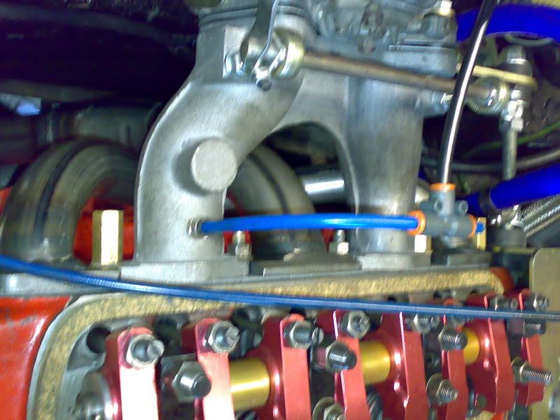
Pic 1
This is a piccy of the vacuum pipework that I am using. It's a bit OTT, but it means that my vacuum reading should hopefuly be an average of the two inlet tracts, rather than just using the one. I've done this because my carb does not have a vacuum take-off! 
Sooo, firstly, you need to think about how to mount your kit. I bought the pickup kit from Specialist Components, which was £115. This comes with a mount for the pickup and a special trigger wheel and mount kit, plus a new bolt for the crank pulley. This kit uses a Magnetti Marelli SEN8D sensor. I got one of those (using that part number as a cross reference) from a local motor factors for around £20.
Pic 2
The kit from Specialist Components, a very helpful firm.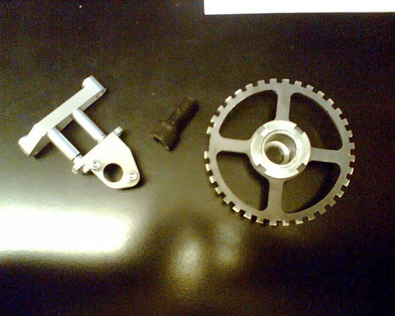
Pic 3
Mounted in the engine bay: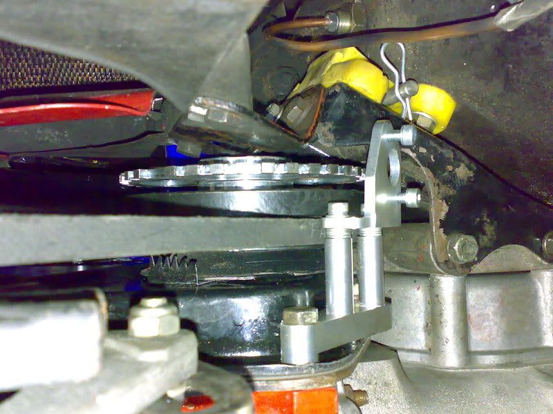
Pic 4
Mounted on the semi-built engine: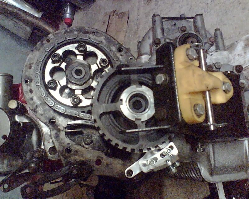
Pic 5
Then, you need to buy a MJLJR kit from AlexF2003 (good guy, easy to deal with and also works with minis a lot, which is a great bonus). From him, the kit is about £140 ish, ready built and set up.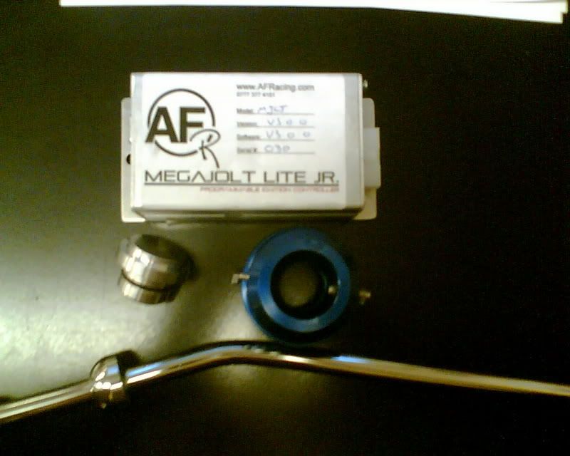
Pic 6
Then, you need a second hand EDIS kit from a ford (I paid £30 off ebay, but you can probably get them a lot cheaper if you are willing to go to a scrapyard and get dirty).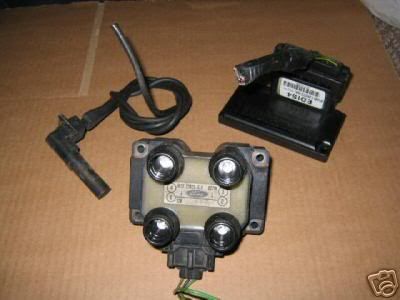
Pic 7
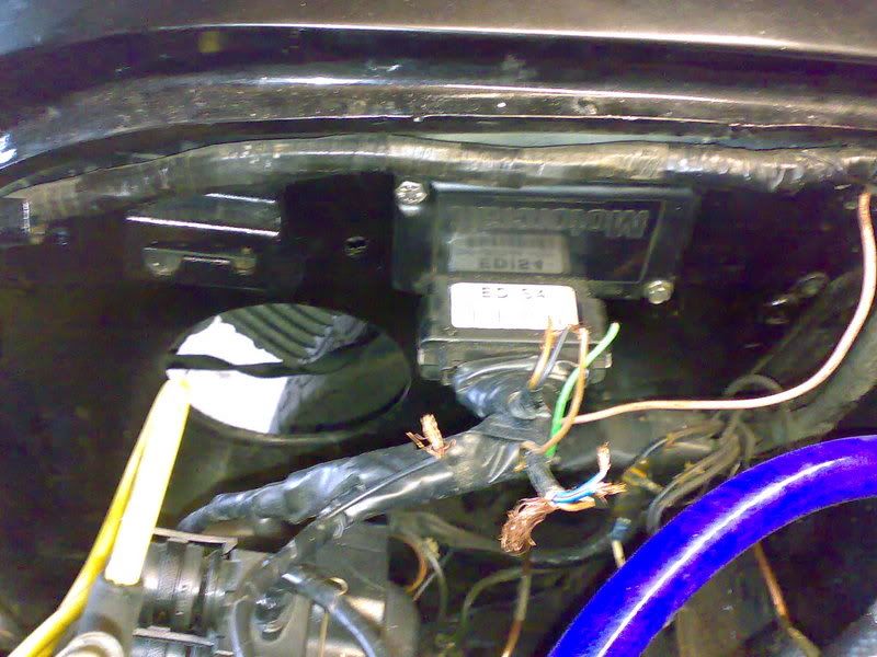
I mounted mine to the inner wing, above the solenoid, like zis (wiring unfinished at this stage: 
Pic 8
I mounted the coil on an upturned mini coil clamp bracket, which I bolted to one of the crankcase breather bolts. Like zis: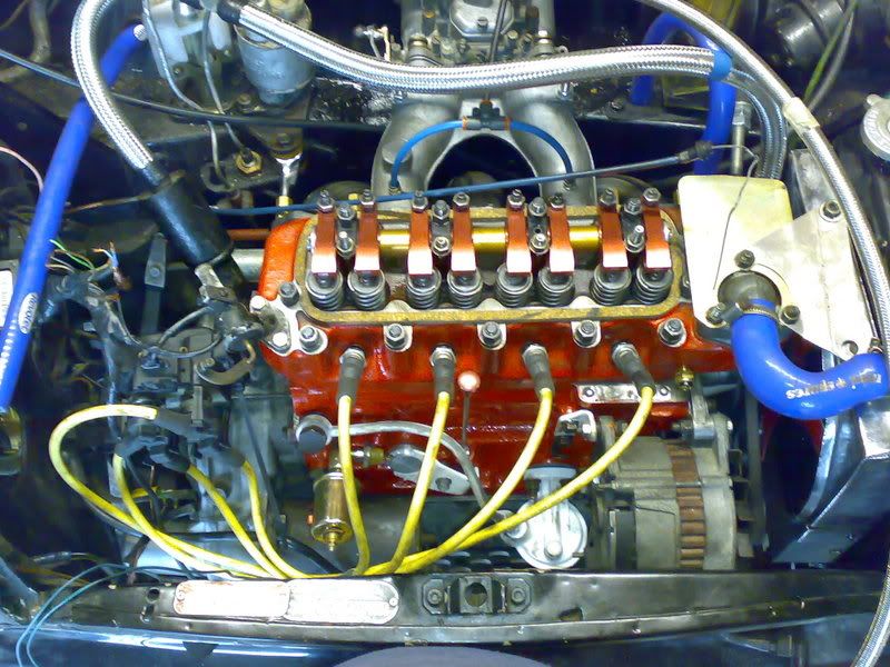
Pic 9
Lastly, you'll need a dizzy blanking plug from MRA Minis, I paid £6 off ebay for it I think.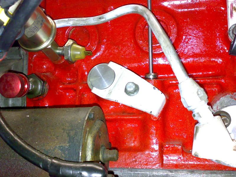
Sooo, once you've got all that. The mount kit is really straight forward. Take the bolt out of the bottom pulley, leave the bottom pulley in place, attach the trigger wheel to the 'top-hat' that sits inside the pulley, replace the old pulley bolt with the special new one. You then attach the pickup mount to the timing case bolts. Take your dizzy out, put the blanking plug in its place (as shown in Pic 9).
Sort out a route for your wiring loom. Sort out where to mount your coil, then pop to halfords and spend £30 on a set of leads that are the right length (lumention hotwires ones) and the kit shown below, which converts normal type leads into the type needed for the Ford coil pack.:
Pic 10
Pic 11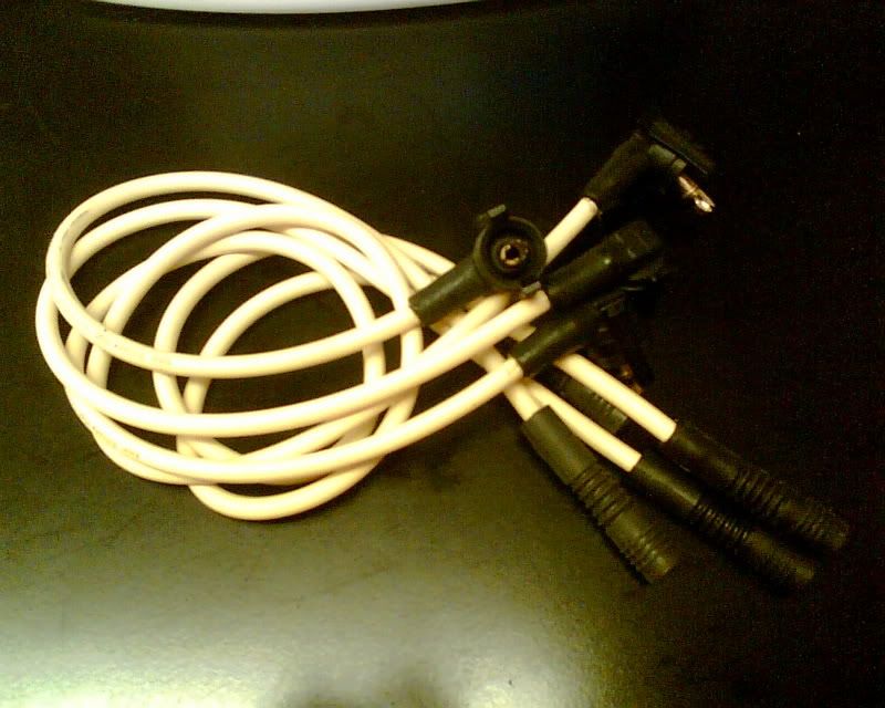
Pic 12
The leads need to have this type of end to mate with the ford coil pack: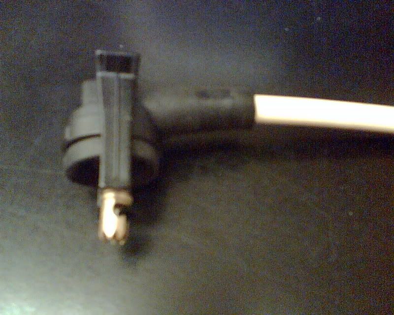
Pic 13
Where I mounted my MJ. I put it here so that I can easily plug the laptop in and leave it sitting on the passenger seat, whilst I fettle the ignition maps: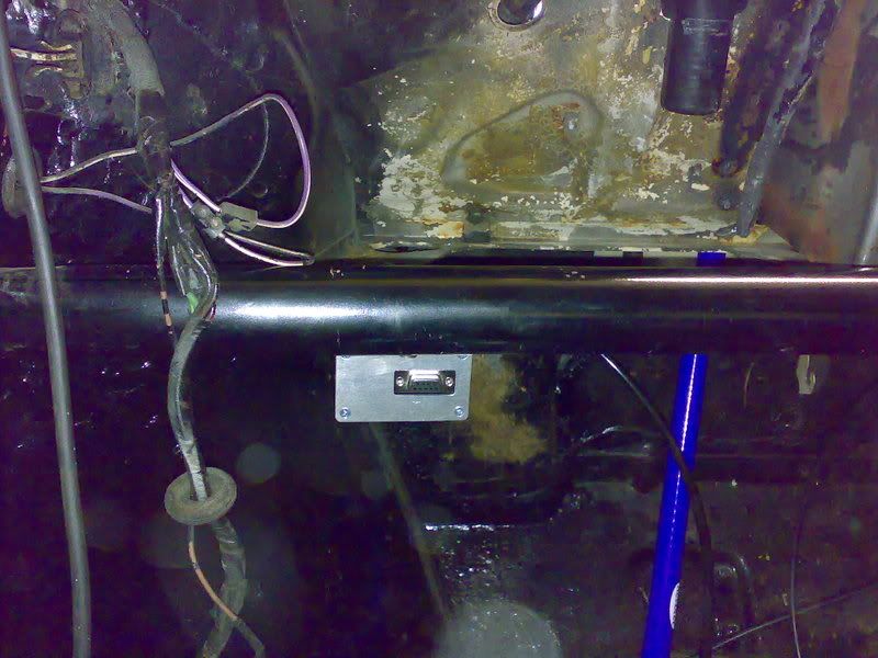
Soo, once you've done all of that. You've got the kit fitted. Now you need to mount your Jolt ECU somewhere inside the car. I mounted mine as shown in the above picture (please forgive the shabbiness of the car, it's from where I took the soundproofing off etc and hadn't been tidied up in that photo). You also need to extend your vacuum take off so it's long enough to reach the ignition module (the bit that comes with the EDIS kit). I've got mine mounted on the inner wing, above the starter solenoid, so the original carb-dizzy vacuum hose will reach to there. Now, you've got everything mounted and you need to make your wiring looms. That is OK if you knwo anything about electrics, just a simple bit of soldering, there is loads of info, with diagrams on the picasso.org site (the maker of Megajolt).
Diagram 1
Okies, so here's a rouhg wiring diagram for the EDIS 4 section of the installation. The piccy shows the harness/multiplug side of the connection: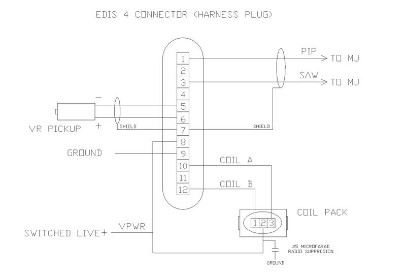
Diagram 2
Now, here's a view of the MJ connector pin out. This is as if you were looking at the end of the Megajolt: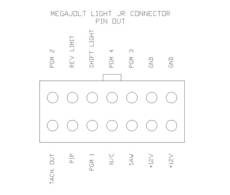
Now, you should be somewhere near being able to power her up and let her rip.
The MJLJR has a built in output for a rev limiter, shift light and also for a rev counter. You can download the PC software off the picasso.org site for free, so you can have a look at how the ignition maps work.
Sooo, total cost, around £300ish, level of skill needed, fair-moderate, time, meh, easy in a weekend if you concentrate. Results, dunno yet! Should be good!  No more starting problems in the damp, mappable ignition, less lumpiness on lairy cams....................
Think that's about it!
EDIT (15/11/14): A quick note about spark resistance, I'm informed that you need to either use resistor type plugs, or resistor type plug leads, but can't use both. So as most modern leads are NOT resistance type ones, it's recommended that you use a resistor type spark plug. Something like a BPR6ES from NGK would suffice.
FIG 1 shown below:
Attached Files
-
 pulleyviews.jpg 105.13K
733 downloads
pulleyviews.jpg 105.13K
733 downloads