Not sure if this helps but I've done the conversion, and wrote a little guide for my local club's forum just the other day. I know people probably wont agree with the way I have gone about doing it, but it works........ I'm happy with it...... so just use it for referencing.
==============================================================
Follow this guide at your own risk
![=]](https://www.theminiforum.co.uk/forums/public/style_emoticons/default/grinwink.gif)
if you set your mini on fire its your own fault
What we gonna do?Most young mini's have either the 2 or 3 clock setup which is in front of the driver, so this is a guide on how to convert your wiring loom so that your mini can have a center speedo. I dont cover 'extra' 52mm gauges in
this guide such as water temp, etc.
What we gonna need?- Tools to take your dashboard out. Spanners, sockets, etc.
- Snips, crimps, flathead screwdriver.
- Spade connectors (male & female).
- Cable ties.
- x2 warning lights.
- Insulation tape.
- Super glue / hot glue sticks.
- Voltage Stabiliser.
- A few
different coloured lengths of wire.
- Electrical lego bricks (junction connectors? ???)
- Speedo cable threaded at both ends, for a center speedo.
Let us begin.....
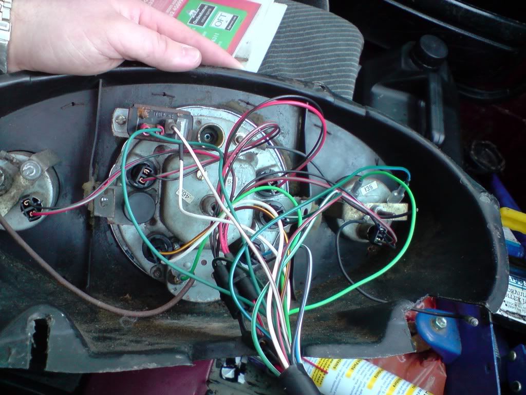
First thing you are going to want to do is take the 2/3 clock setup out. So remove the surround by undoing the screws securing it to the bracket. Then undo the bolts holding the clocks to the bulkhead bracket.
To remove the clocks, you need to squeeze the white connector on the end of the speedo cable whilst also pulling it out of the back of the clock. Then unplug the connector (and rev counter cables if you have a 3 clock) and the clocks should be free.
If you are still going to have a rev counter, then make sure once you disconnect the two wires going into the rev counter pod that you label them with masking tape (or an alternative method) so that you arent wondering why there are 2 lose cables behind your dash.
Finally, go into the engine bay and using the correct size socket, remove the 4 nuts securing the bulkhead bracket inside the car. You are now left with lots of open space in front of you


Now, the plug that fits into the 2/3 clock setup needs to be chopped off so that we can wire in the center speedo.
NOTE : Cut the wires about 3inches from the plug so that if you do want to convert back in the future you can rejoin the wires.
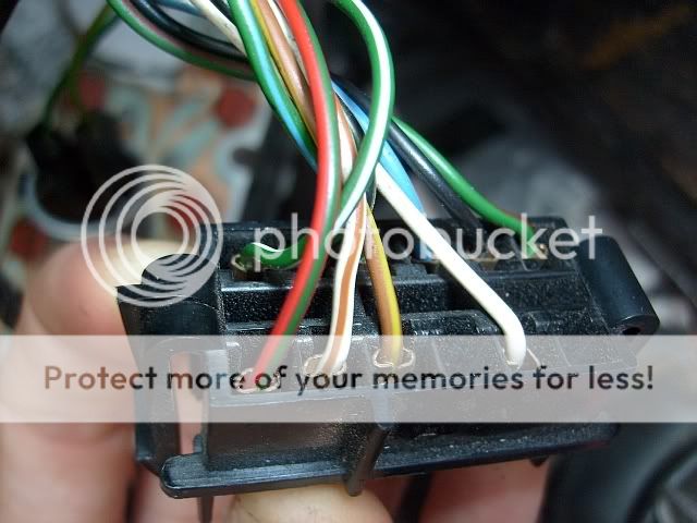
A breakdown of the wire colours :
- Red with green - - - Dash illumination.
- White with brown - - - Oil pressure warning light.
- Brown with yellow - - - Ignition warning light.
- White - - - Ignition live.

- Green with red - - - Left indicator warning light.
- Black - - - Earth.
- Blue with White - - - High beams warning light.
- Green with blue - - - Water temperature gauge feed.
- Green with back - - - Fuel gauge feed.
- Green with White - - - Right indicator warning light.
Once you have cut the plug off, you will need to strip some of the insulation tape away so you can seperate the wires out.

Starting with the indicator warning lights, you will need a pair of these....

.....take the green with red wire and crimp a female spade connector onto it, do the same to the green with white wire too. Now you will need some black (or whatever colour you chose to use as earth) coloured wire and cut two lengths which are slightly longer than the indicator warning light wires. Crimp a female spade connector onto one end of each cable, wrap the four wires into pairs (two per indicator, one black one coloured) and push the spade connectors onto the warning light.
You should have something like this....

....the bare ends of the black wires will be close to the original loom.
If you want only one single indicator warning light, ie. only one light that flashes when both indicating left and right. Then simply connect the green with red and green with white wires to the same warning light.
Now the main wiring loom that goes to the center speedo needs to be wrapped. Seperate the green with blue wire from the other wires as this is for the water temperate gauge which is not part of the center speedo. You will also need a length of black wire.

Using a single piece of junction connector (or other method if you prefere, such as soldering), strip and insert the black wire that was the original earth for the clocks and the two stripped black wires from the indicator warning lights and tighten the screw to hold them in place. Strip and insert one end of a new length of black wire and tighten the screw down. Wrap this new earth wire with the other coloured wires and you should have something similar to this.

Three sets of wrapped cables. Two for the indicator warning lights and one which is the main wiring loom for the center speedo. Ignore the other things in the photo as I had to do some minor surgery on my loom.
You can test that the indicator warning lights still work by flipping the hazard warning switch, but be sure to test the individual indicators too as you may have accidently disturbed the flasher relay :
If your center speedo already has bulbs, wiring, etc. then you can skip this section. But if you are unfortunate enough to be in the same situation I was in then, then do read on
My center speedo had nothing at all, not even bulb holders, so I'm going to show you how to do it from scratch
NOTE : I took mine apart to clean so there is no mechanism inside which is why you cannot see the speedo drive thread.

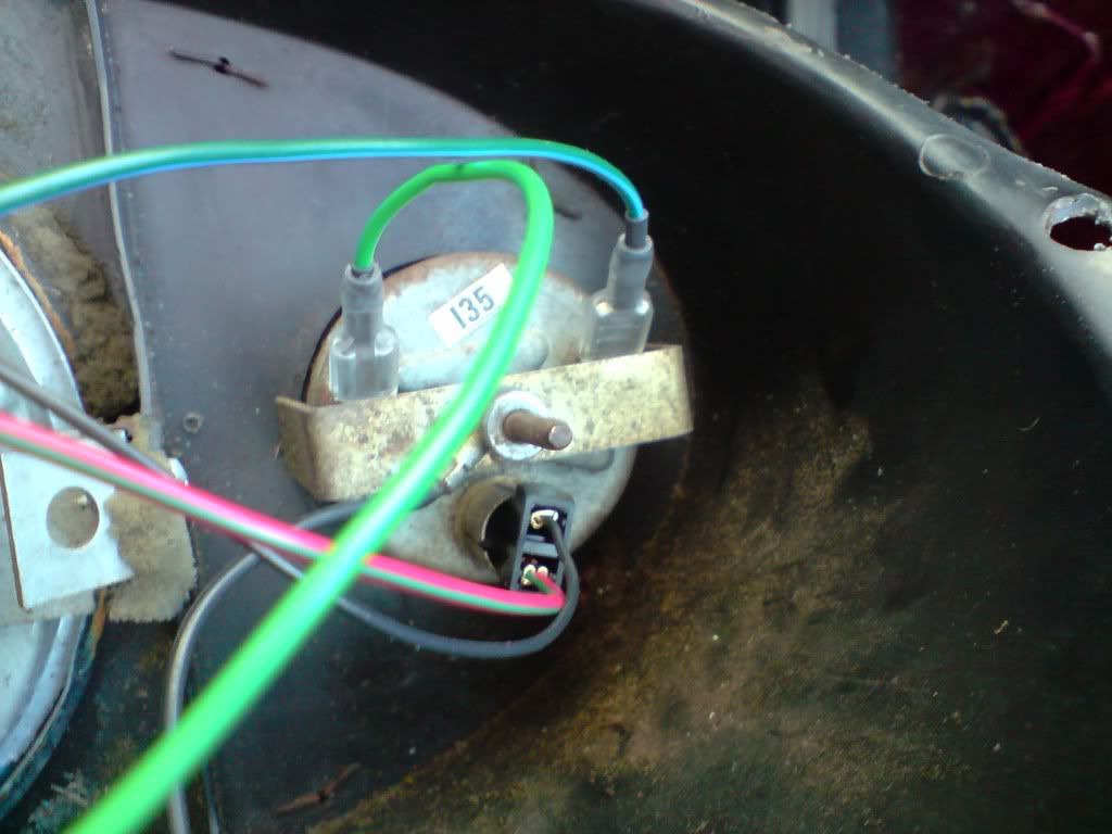
Firstly had to super glue some rubber washers over the illumination holes, all will be revealed as you read on.

Secondly needed a voltage stabiliser to get the fuel and water temperate gauges working.....
This is the time when you are going to need lots of different coloured wires.

The voltage stabiliser requires earthing, so unless you are going to earth your center speedo in some other way you will need to run a short length of black cable from the voltage stabiliser to the earth on the loom. For the fuel gauge to work you will need to crimp and run a short length of wire (yellow) from the
I connector on the voltage stabiliser to either of the connectors on the fuel gauge.

This is why I needed those rubber washers, to stop the bulbs from earthing on the speedo's casing. These are just butchered bulb holders from the 3 clock setup I removed, I'm sure there are better ways of going about it but it was my chosen method

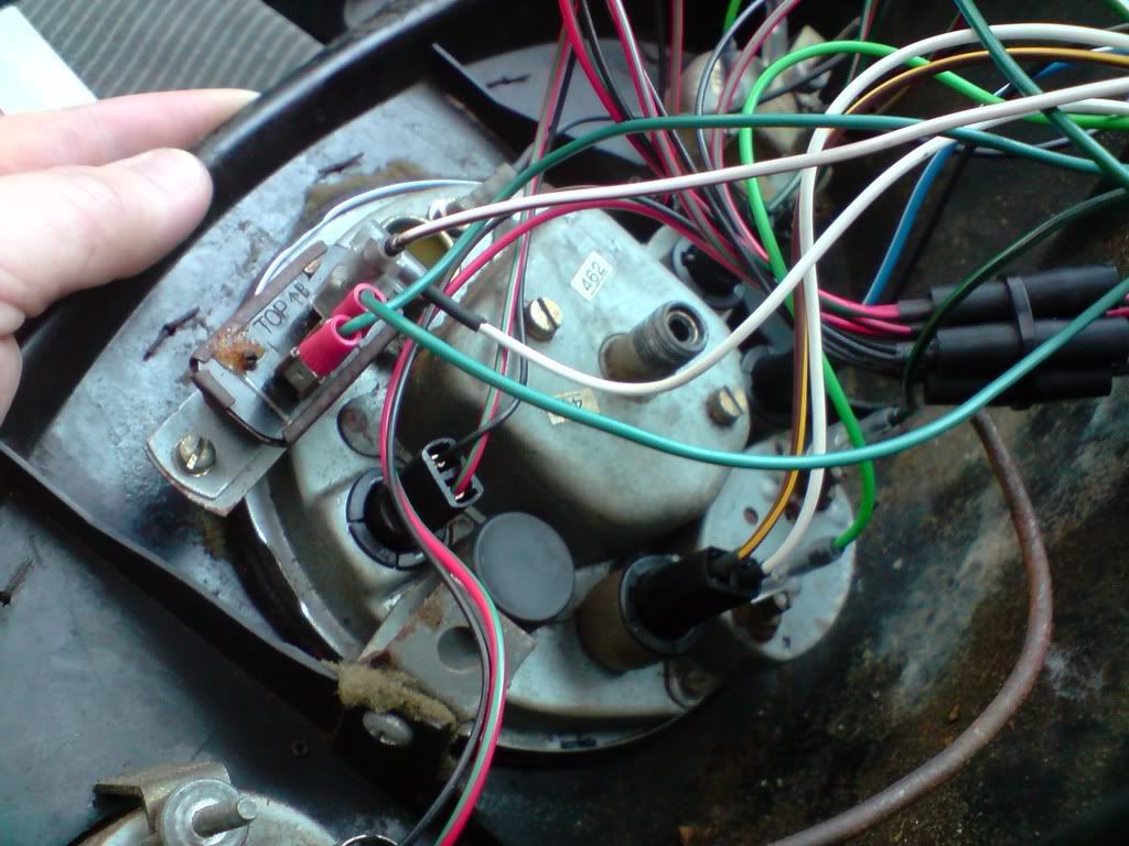
This is the wiring loom I made for the center speedo.
- Green - - - Fuel gauge feed.
- Purple - - - High beams warning light.
- Blue - - - Ignition warning light.
- Orange - - - Oil pressure warning light.
- Black - - - Earth.
- White - - Ignition live.
- Red - - - Dash illumination.

This might look like a mess, but if you follow the wiring diagram I pictured further up then you can just look at this picture for reference. I have used three bigger junction connectors as there are more than 2 wires going into them.
The final step is to join the new wiring loom (or the one already existing on your speedo if your lucky enough!) to the one in your mini using junction connectors (or your prefered method). If you have followed my wire colouring scheme then this how the wires will join up :
- Green with black > Green - - - Fuel gauge feed.
- Blue with white > Purple - - - High beams warning light.
- Brown with yellow > Blue - - - Ignition warning light.
- White with brown > Orange - - - Oil pressure warning light.
- Black > Black - - - Earth.
- White > White - - Ignition live.
- Red with green > Red - - - Dash illumination.
If you have existing wires on your speedo, then you will have to look at the pictures and wiring diagram and work it out yourself

/
Thread your new speedo cable onto the speedo drive in the engine bay, feed it through the bulkhead, and then gently thread it onto the back of the center speedo. The only way your gonna know if you done it right is to go for a spin

If your wiring is any good, then when you turn the ignition on you should be greeted by a green and a red light until you start the engine. They should both go out after a couple of seconds so if they stay on you either have a problem with your wiring somewhere or something wrong with your engine
The fuel gauge will also start creeping up too.
Hope this guide helps anyone who is looking to convert to center speedo, it's DIY at its finest so follow this guide at your own risk.


![=]](https://www.theminiforum.co.uk/forums/public/style_emoticons/default/wink.png)
 lol ended up using IE lol

![=]](https://www.theminiforum.co.uk/forums/public/style_emoticons/default/crazy.gif) )
)


