


pdf format attached.
Classic Mini to Nissan Micra (cg13de) Wiring Guide
By Ian Cooper
Introduction
So you’ve decided to swap to injection and enjoy the modern advantages of a newer designed engine. A conversion such as this it difficult but worth doing imo, and I seem to find a lot of people put off the complexities of injection and more modern components by the wiring. It really was the easiest bit of my conversion so I have put together this quick guide on how to wire up a cg13de engine inside a classic mini.
Notes
I can take no responsibility for any damage you do to yourselves or your cars by following this guide. Although it is meant as a set of instructions to make the process easier, your cars or engines may be different and you must apply logic as well to what I am saying.
Car electrics although safe enough can be incredibly dangerous to your beloved minis if incorrectly done. Make sure to fuse connections where appropriate, and take the proper precautions when taking wires through sharp holes in the bulkhead and close to hot objects in the engine bay.
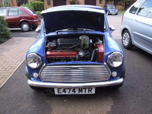
My mini is a 1988 Mini City E, the engine is a cg13de from a 1993 Nissan Micra (UK). This is how I have wired my car, it perhaps isn’t the best way to do things and your cars/engines may be different. You have been warned.
I would suggest disconnection of the battery whilst wiring. And only connecting it when testing. This way you should avoid major problems.
I would recommend reading the whole guide, not just the wiring diagram as it may not make sense without the first bits!
I have tried to put in all the wires needed, however, I may have missed a few off, using some common sense if you work out any I have missed please contact me and I will edit them in! (it was a long time in between wiring the car and making this document so please forgive my memory mistakes!)
Useful Link
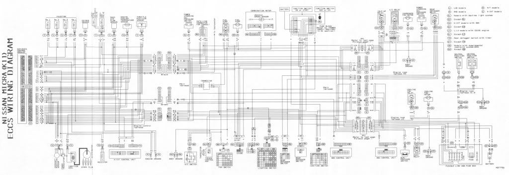
Link to a k11_no NATS wiring diagram, this is what I assembled my entire guide from and how I wired my car, it is simple enough but you should be able to get away without it if you follow how I have done it.
This may be very useful if I have missed some wires off the plugs, it is easy enough to trace them to where they are going, don’t worry its not so bad, a lot of the gubbins on there are not necessary for what we are doing.
http://i249.photobuc...k11_no-nats.jpg
Wiring Instructions Begin Here!
Step 1 – Harvesting the correct loom
First you’re going to need to get the loom from the Micra. Ensure that you got everything from the front end of the micra as this will make life easier. Obviously the ECU (mounted somewhere under the dash is essential).
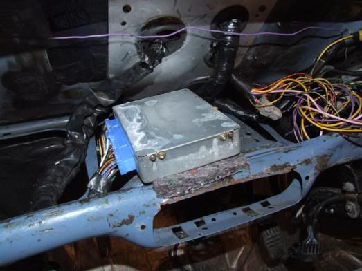
ECU looks like this:
http://i249.photobuc...k11_no-nats.jpg
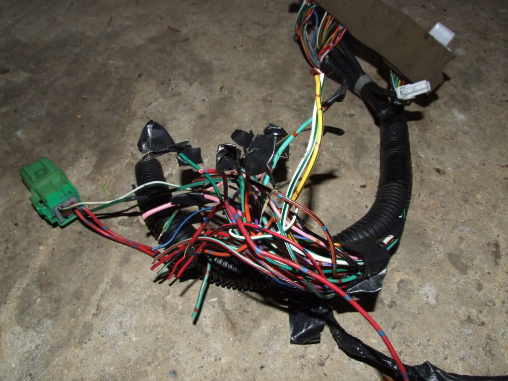
You will find that the loom is actually 3 individual looms, there is a section that connects to the engine (lots of connectors on this!) and then goes through the bulkhead to the ECU. This is the main loom you want.
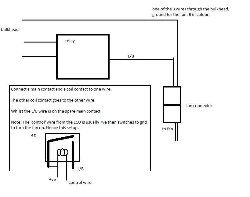
You will also find two other looms, a left and right hand side. You will need only the right hand side for this guide. This right hand side has the starter wire on it as well as the neutral position switch. There is also a fan motor connector we will need. Both of these looms have some useful relays and such in, you will need a couple for this guide and these are always worth keeping for future projects!
The battery terminals and cables can be discarded. However the first step of this guide you will need the small red connector found on the +ve battery terminal. Unbolt this.
Step 2 – Connection to battery
All cars need +ve and –ve to the engine for various bits. As with the mini I have kept the battery +ve cable running along the bottom of the car and up onto the solenoid on the engine. This will provide lots of starting current to the starter motor. Then we tap off of this connection for our +ve everywhere else. –Ve is simply connected to the shell of the car.
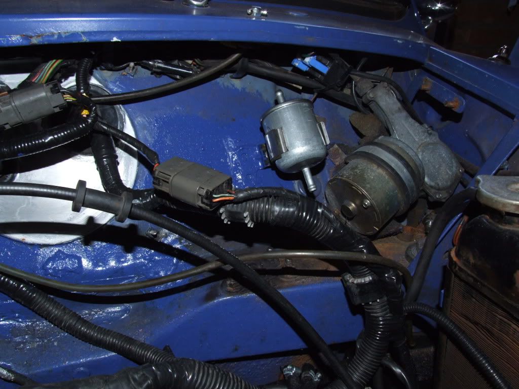
Remember that red connector I spoke of. This and your main thick battery cable will need to be bolted to the solenoid (there is a thread on there; you want the thicker of the 2 studs.) DON’T OVERTIGHTEN THESE AS YOU WILL EASILY STRIP THE THREADS. The red connector has 2 convenient spade terminals inside it, and your micra used this to power everything else on the car, we shall use the same!
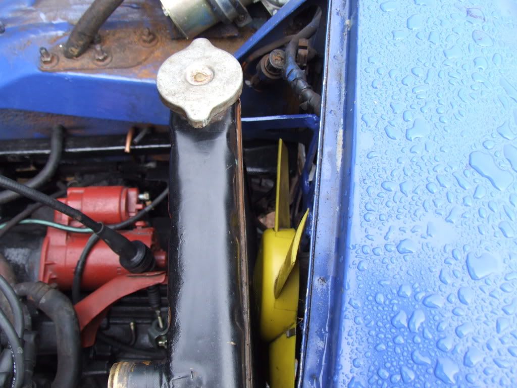
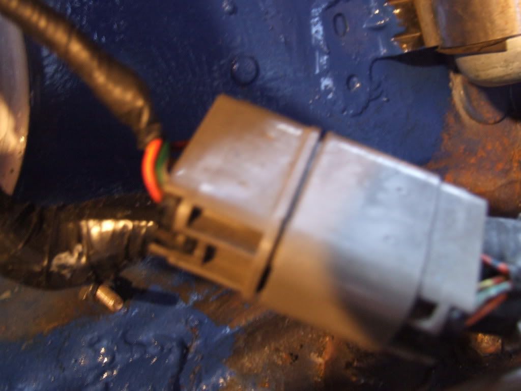
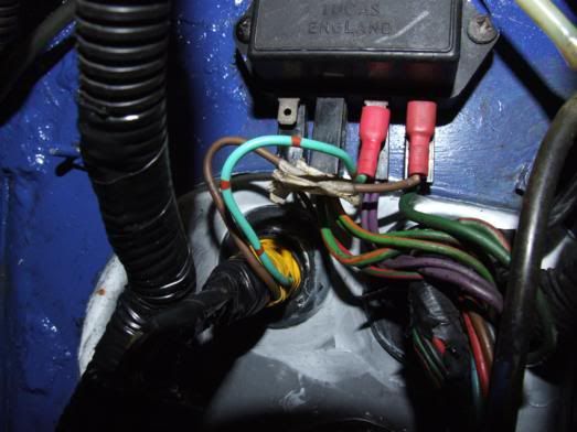
You can see in this image the solenoid stud.
Here we see the red terminal with 2 nice connectors on it harvested from my micra loom
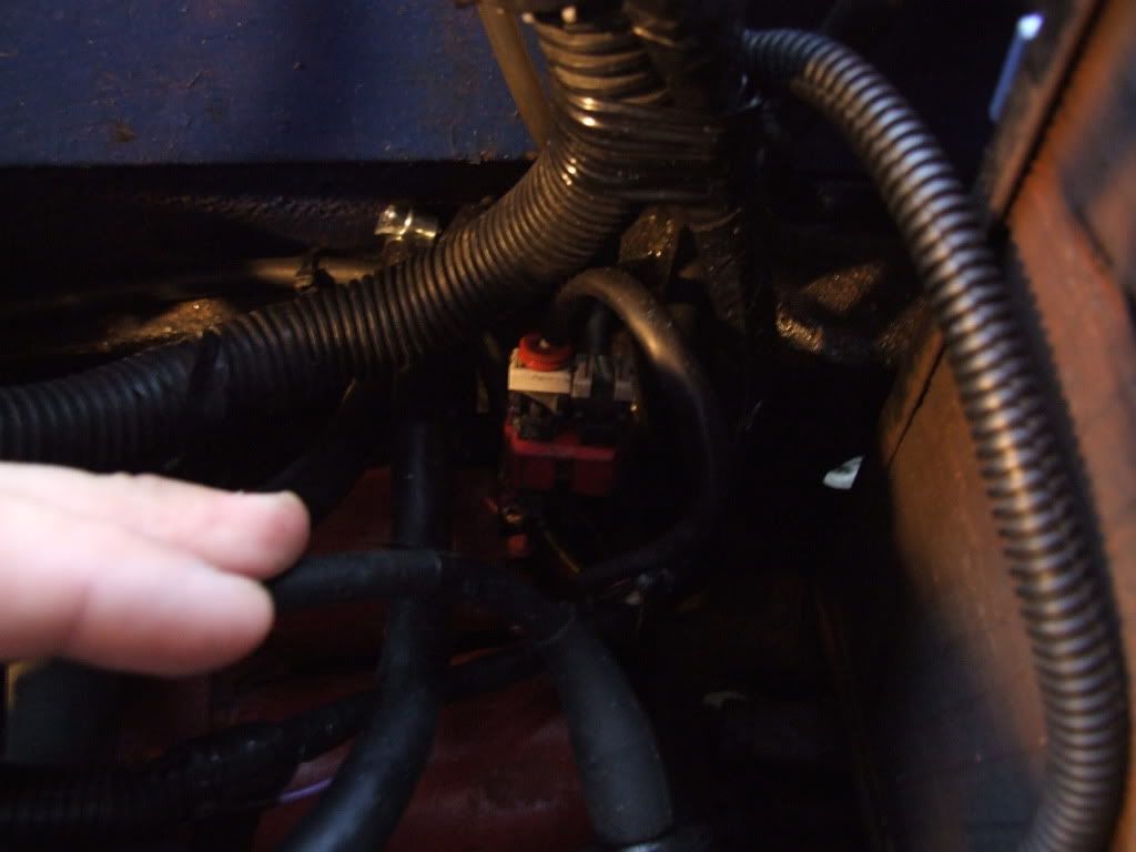
Next we want to earth the engine.
I have connected my earth as shown in the picture. Nice and easy to check and I do like a good place to put a probe in order to test voltages in the engine bay (This is useful!). Basically insure all surfaces are shiny before bolting together.
Power the Mini
To keep the wiring easy I have literally left the mini section of wiring separate from the micra. The main this that connects the 2 is that red terminal, and this is only to get +ve to the mini loom!
Now. Somewhere on you micra loom you should find a connector that fits into one side of that red connector nicely. It should have a W/G (white with green trace) wire on it. Follow this wire about 4 foot into a fuse box (if memory serves) and cut it. This isn’t a needed wire to us (I believe it did the micras headlights or such) and it will be useful for our purposes.
SAFETY: Anything you connect to this red terminal is VERY LIVE. What I mean by this is that with no fusing present if the wire connects to –ve it will draw a lot of current from the battery. This is bad. To avoid catastrophy keep dangerous wires such as these away from hot/moving parts and shield properly.
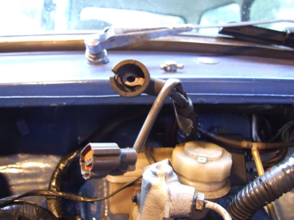
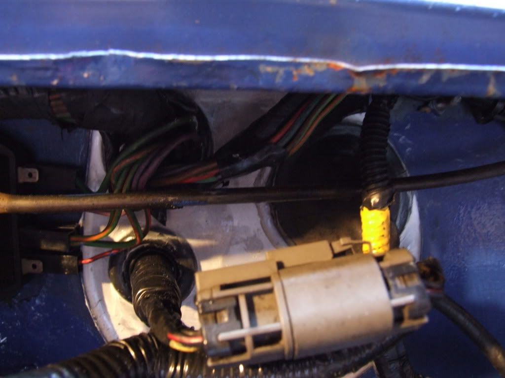
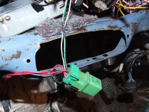
You can see in this picture I have shielded this wire with a plastic shroud and it has since been tacked to the radiator surround with zip ties to keep it out the way.
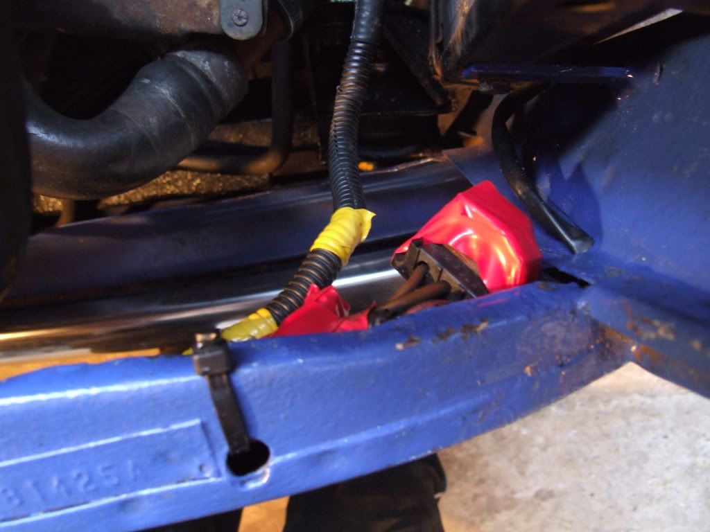
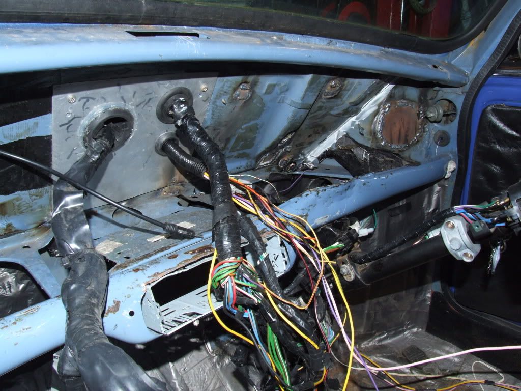
You should find that all your mini wiring loom tucks neatly into the slam panel. Insure you cover any unused connectors with a good bit of insulation. Using this method it is very easy to switch back to an A series engine. In the picture you can’t see it but our new +ve wire W/G goes to one of the circular ring connectors on the mini loom. This will have 2 brown wires going off into the slam panel. These brown wires originally were connected straight to the solenoid of the mini before. All we have done is replicate this! Insure you cover any unused connectors with a good bit of insulation. (this is important so it is here twice!)
Now assuming you got all the above steps correct all the minis bits and pieces should work (wipers, headlights etc)!
Step 3 – Main loom connection
Easiest bit, basically you plug the micra loom onto the micra engine. It should be fairly self-explanatory as only one connector will fit on one bit of engine
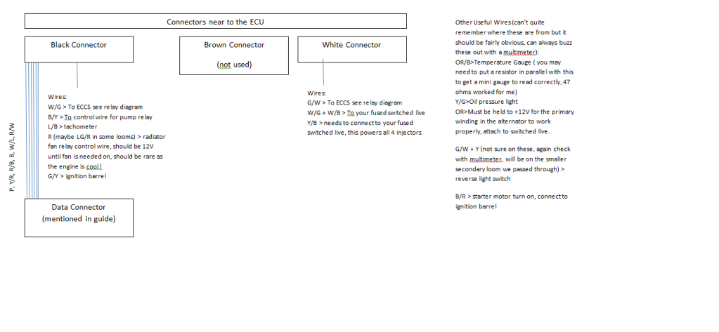
 The only bit you can mess up is the injectors so here is the sequence:
1. G/Y
2. L/R
3. L
4. BR
You also need to earth some bits of this loom to the block, should be obvious where to do this….mine are all bolted on to the back of the engine near the dizzy.
Step 4 – Secondary loom connection
This is the right hand part I talked about. You will only need a short section of this and I will do my best to describe what you need here (some common sense may need to be applied)
Now although your main loom had most of the engine bits on it, we still havn’t connected wires to the gearbox. There is 2 connectors here of which you neeed the reverse switch (legal requirement to have a reverse light). The neutral position switch isn’t needed but I wired it up anyway (perhaps I shall do something clever with this at another time!)
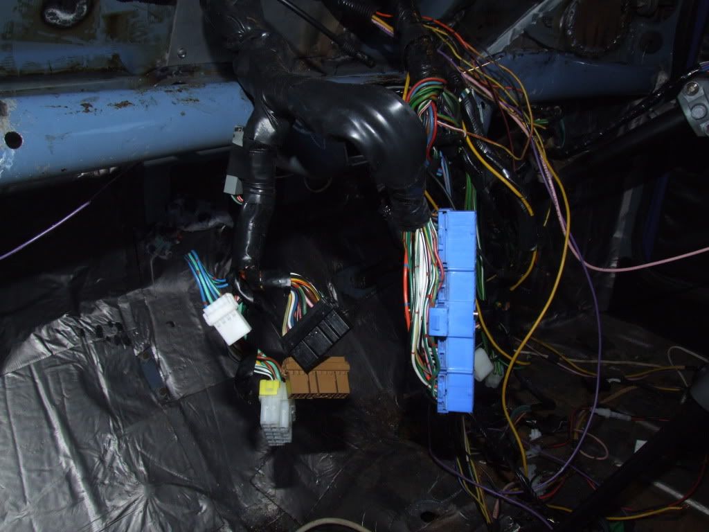
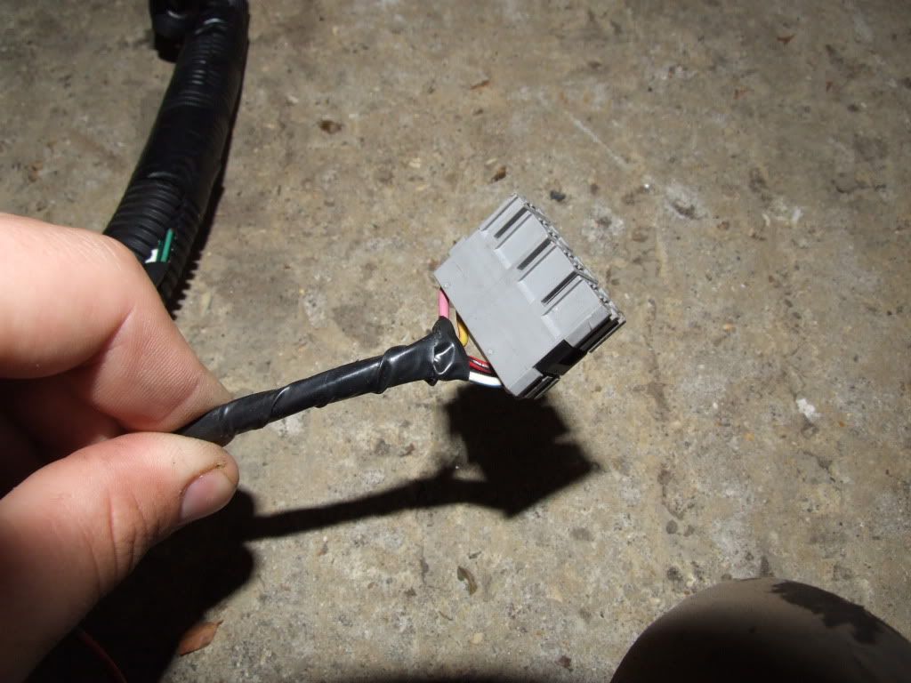
Basically on this loom you need this connector…
….down to the 2 connectors for the gearbox. There should also be a B/R wire on this with a circle style crimp on it. This connects straight to the other smaller thread on the solenoid (this is your starting signal!) There is also some other wires on this bit that are used for the alternator, this are also important and shouldn’t need extending or anything if you have placed your alternator where mine is.
Alternator connectors
You should also find another of the connectors you used on the W/G wire, but this time on a W/R wire. Connect this to the red connector on the solenoid. This is the alternator power wire and will allow the alternator to charge the battery.
Attached Files
-
 Classic_Mini_to_Nissan_Micra.pdf 234.64K
398 downloads
Classic_Mini_to_Nissan_Micra.pdf 234.64K
398 downloads
Edited by drummerian, 23 September 2010 - 11:17 PM.


