Jump to content


Photo
- - - - -

1982 Austin Mini - Project Who?


  • Please log in to reply
848 replies to this topic

#631 JonnyAlpha

JonnyAlpha

    Up Into Fourth

  • Members
  • PipPipPipPipPipPipPipPipPip
  • 2,744 posts
  • Location: North Devon
  • Local Club: Exmoor Minis

Posted 28 December 2016 - 07:28 PM

So today after finishing the console I did some more work on the speaker board. Now that I have opened my Chrisy Pressies, I cut out the template for the speakers and used it to mark out where the cut the recesses for mine:


IMAG7426_zpsqw5jmnqa.jpg


IMAG7427_zpsb2de93if.jpg


As I am mounting the speaker board under the rear seats I decided to secure it by using a bolt through the centre support for the rear seat. The only problem is that the strut is not vertical. To combat this I made a wedge to hold the speaker board vertical but I needed to secure a piece of threaded bar in centre strut. I needed to find a way of holding the threaded bar horizontal. To do this I came up with the idea of bending a couple of large penny washers:


IMAG7428_zpswjxdopwi.jpg


IMAG7429_zpsntekd67x.jpg


Then I did I dry fit:


IMAG7430_zpsnnjqrrn2.jpg


IMAG7431_zps9ochiikx.jpg


Then I applied some primer on the speaker board:


IMAG7436_zps1wv7eyqg.jpg


#632 JonnyAlpha

JonnyAlpha

    Up Into Fourth

  • Members
  • PipPipPipPipPipPipPipPipPip
  • 2,744 posts
  • Location: North Devon
  • Local Club: Exmoor Minis

Posted 28 December 2016 - 09:34 PM

While I was waiting for the primer to dry I had a look at where I was going to put the amp - Christmas Pressie:


IMAG7432_zpsde8jtnnk.jpg


Initially I envisaged putting the amp under the rear seat and installing a couple of 12v fans for cooling however once I got this amp I realised that it is too wide to fit. I had a look at several other options such as under a front seat under the dash (both too small).

Another option I considered was putting it in one of the companion bins. This would work but would need a clever bit of woodwork to mount it.


In the end I opted for the most practical place - the boot. I didn't really want to put it in the boot as I wanted it keep it in the main area of the car however I came up with the cunning idea of mounting it under the rear parcel shelf. Hopefully it will tuck nicely out of the way to avoid damage when putting things in and out.


I measure and marked out a piece of plywood on which to mount the amp. This will be bolted to some pre existing holes in the shelf:


IMAG7441_zpsz6mahlz0.jpg


There should be enough room on the board to mount the amp and also secure the wiring.    


#633 JonnyAlpha

JonnyAlpha

    Up Into Fourth

  • Members
  • PipPipPipPipPipPipPipPipPip
  • 2,744 posts
  • Location: North Devon
  • Local Club: Exmoor Minis

Posted 02 January 2017 - 06:26 PM

Not a lot done today. Spent most of the afternoon test wiring up my new (S/H) Sony XPLOD Head Unit, couldn't get any sound and spent ages going through various settings only to find that one of the ISO connectors is dodgy - it's either the one that connects into the back of the unit (that came with it) or the ISO female to bare wire one that I bought from Ebay? Damm annoying.


In between trying to sort out the above I slapped some silk black wood paint on the speaker board:


IMAG7462_zpsoh0fcuyt.jpg


#634 JonnyAlpha

JonnyAlpha

    Up Into Fourth

  • Members
  • PipPipPipPipPipPipPipPipPip
  • 2,744 posts
  • Location: North Devon
  • Local Club: Exmoor Minis

Posted 07 January 2017 - 06:03 PM

A horrible wet dreary day but I managed a little.


I needed to mark the amp mounting board to see where I could mount it using existing holes. Working on my own I had to wedge it up under the parcel shelf with a couple of pieces of wood:


IMAG7475_zps13t9bade.jpg


I then spent ages trying to decide on the best location for the Amp and how to avoid catching the Amp on the bolts securing the board.


IMAG7477_zpssxh3yhu7.jpg


I also had to anticipate where the various power and speaker cables would run and take this into consideration:


IMAG7480_zpsahw5udqg.jpg

This board as you can see it will be upside down and the narrow side of the board will be nearest the battery.


The power and ground cables will run around the RH side as you can see it now, around the rear and then secured to the rear of the back seat onto the battery (with a fuse between the amp and battery +).


The Gnd cable will be fixed to a bolt in the underside of the parcel shelf.


The speaker cables and maybe the RCA will run to the left (as you can see it now) towards the rear and then run between the rear seat and rear quarter panel across the companion bin and under the rear seat where the speakers are fitted.


The speaker wires may cross the power cable but if the do it will be perpendicular to avoid interference. The RCA cable will likely run alongside the speaker wires.


The amp remote will probably follow the power cables but instead of running to the battery side of the car it will run the opposite direction into the passenger compartment and up under the passenger seat to the radio. I may run the RCA the same way?


Here is the installation kit. It's a Rockford Fosgate, good quality with plenty of cable and pre terminated ends.


IMAG7479_zpsvmw9illc.jpg


The RCA cable is sitting in the car :-)


#635 JonnyAlpha

JonnyAlpha

    Up Into Fourth

  • Members
  • PipPipPipPipPipPipPipPipPip
  • 2,744 posts
  • Location: North Devon
  • Local Club: Exmoor Minis

Posted 08 January 2017 - 07:45 PM

Well a little more work today weather was a little unsettled but managed.

After working out where to mount the amp I set about prepping how to secure it. I sussed out which bolts to use from my every dwindling supply and drilled out the amp mounting board. Sorry about this but here's a hole:


IMAG7481_zpspgdcqvdw.jpg


And a bolt:


IMAG7482_zpszv2ld1cu.jpg


Probably not needed but I decided to put some Tap Washers on the back of the board to act as an anti vibration mounting:


IMAG7483_zpset0a5bt6.jpg


I also put some smaller tap washers between the amp and the board. Again to help dampen vibration and to stop the bolts going through the mounting board.


Here it is test fitted in place:


IMAG7485_zps9xhyngbw.jpg


Time to clean up the mounting board and fill some cracks before painting:


IMAG7486_zpsalmf3gmx.jpg


I then put some primer on and while I was waiting for it to dry I mounted the speakers in the speaker board that I made the other day:


IMAG7487_zpsjhljz8ff.jpg


I then fitted it in the car to have a look at it in place:


IMAG7488_zpsum7vgxnj.jpg


 I made a mistake when measuring it and with the mats in place it doesn't fit so I have had to pull them forward. It is also a little to high but that's not an issue:


Close Up:


IMAG7490_zpsokxmyy44.jpg


And closer still:


IMAG7491_zps8ghwberq.jpg


Can't wait to get the wired up and booming!!


Back to the amp - when the primer was dry I put on the top coat:


IMAG7492_zpsi5qtef6c.jpg


And then once that was dry I mounted the amp:


IMAG7494_zpsa18ghxit.jpg


It was too late to start wiring it up and it's not something aught to rush as I need to do it properly e.g. cut strip and tin the ends and plan the routing properly.


Weather is set to be crappy most of the week so maybe next Sunday I'll get the amp wired in ?


#636 paulrockliffe

paulrockliffe

    Camshaft & Stage Two Head

  • Members
  • PipPipPipPipPipPipPipPip
  • 1,763 posts
  • Location: Durham

Posted 08 January 2017 - 09:06 PM

Are you sure you want to use the ammeter?  I remember looking at these a few years ago, the only way they can measure the current draw is if you wire them in series with the current draw isn't it?  That means you have to run all of your electrics (other than your starter motor) through the gauge, if the gauge fails, everything is gone.


#637 JonnyAlpha

JonnyAlpha

    Up Into Fourth

  • Members
  • PipPipPipPipPipPipPipPipPip
  • 2,744 posts
  • Location: North Devon
  • Local Club: Exmoor Minis

Posted 23 January 2017 - 08:58 PM

Are you sure you want to use the ammeter?  I remember looking at these a few years ago, the only way they can measure the current draw is if you wire them in series with the current draw isn't it?  That means you have to run all of your electrics (other than your starter motor) through the gauge, if the gauge fails, everything is gone.

Not even looked at how to wire them up. I bought them as a job lot. I also bought a Rev Counter off of eBay which was sold by a Mini Man in the car section and ended up being a cable driven MotorCycle Rev Counter DOH!!


#638 paulrockliffe

paulrockliffe

    Camshaft & Stage Two Head

  • Members
  • PipPipPipPipPipPipPipPip
  • 1,763 posts
  • Location: Durham

Posted 24 January 2017 - 11:00 AM

OK, then have a look at how they work and make sure you understand the risk of failure before you commit.  As I understand it, you risk losing all your electrics, but if they fail the wrong way they could set on fire.


What you could do is find some change-over switches and wire them behind the dash so that if the ammeter failed you could move a switch to divert the power around the ammeter while isolating it.


Personally I don't think an ammeter tells you anything interesting enough to be worth the bother though..


#639 JonnyAlpha

JonnyAlpha

    Up Into Fourth

  • Members
  • PipPipPipPipPipPipPipPipPip
  • 2,744 posts
  • Location: North Devon
  • Local Club: Exmoor Minis

Posted 24 January 2017 - 08:52 PM

Mad a start on the dashboard, partly used a template for the overall size and making my own measurements. Battery died so didn't get any early pics (that I can remember).


Then took a few.


The hole for the Air Vent didn't seem right?

IMAG7537_zpsq8tohnmk.jpg


I still haven't cut it but after trying a few positions I think I have it OK?


First cut out for the instrument panel:


IMAG7541_zps46hfudqu.jpg


This is only for a two dial setup. I want to get a Rev Counter so I am not sure how to proceed until I do?


Here's a pic of testing the location of the gauges etc The holes for the vents are shaded and to the right of the Instrument Dials is a Rev Counter (that I bought in error - it's a Motorbike one!!) There are two more gauges on the left and a 7 inch Touchscreen off centre. Leaving just enough room for a small glove compartment?


IMAG7545_zps6o1ozur8.jpg


Then I set about putting on some form of fixings - did this at the rush and mad a boo boo.


Countersunk holes for screws to hold on some batten:


IMAG7547_zpsdlfj7rgh.jpg


IMAG7548_zpsrzlej23s.jpg


Then two coach bolts through the batten:


IMAG7549_zpss4gtxt7w.jpg


I just need some pieces of firm steel bar to fit over the bolts to pull the dash up against the top and bottom dash rail?


#640 JonnyAlpha

JonnyAlpha

    Up Into Fourth

  • Members
  • PipPipPipPipPipPipPipPipPip
  • 2,744 posts
  • Location: North Devon
  • Local Club: Exmoor Minis

Posted 04 February 2017 - 09:44 PM

Managed a little more progress on the dashboard today. My first fixing strategy failed so I had to have a rethink. I removed the two bolts that I had previously fitted as it turned out they where in the wrong location.


I still needed a fixing point somewhere near the centre to pull the dash in at the centre of its curvature. Pulling the top up against the Top Dash rail was OK but in the centre this is not feasible. Also I felt that I needed an alternative fixing solution as opposed to pulling the whole thing up against the dash rails. After a lot of head scratching I came a solution. I fabricated these out of a couple of Right Angle Brackets:


IMAG7611_zpshrxxatvm.jpg


These would be used to secure a piece of wood to the bottom central area, like this:


IMAG7612_zpsahi1abxe.jpg


The bottom edge of the dash now has something more substantial to butt up against. Once I cut all the holes in the dash I will probably also screw another piece of wood to this piece above to allow me to bolt the lower dash to it and pull it in from the bottom.


This is the dash in place. Secured at the top by only one fitting and just butted up to the bottom piece. It's quite solid already:


IMAG7613_zpsvhaac89u.jpg


I marked and cut the hole for the Rev Counter:


IMAG7615_zpse5ejlqdw.jpg


And then started working on the main instrument cluster centre piece:


IMAG7614_zps5wn26ad9.jpg


This will sit over the area already cut out. I need to build up the lower area so that the instruments are angled upwards towards the driver, like this:


IMG_2408.jpg


I am also still not 100% sure how to cut this piece?


I have placed the cluster on it and marked around the two instruments as well as where the indicator lights will shine through.


What I think I need to do is cut the holes out for the speedo and fuel gauge but make the holes too small so that the the instrument cluster sits behind the facia. Like this.


That's what I think this guy has done, but he also has some chrome inserts which I do not:


IMG_0697.jpg


I also need to cut out the holes for the two other gauges, air vents, touchscreen and glove box. Then I'll cover the main dash in white and all of the inserts will be black. 


#641 JonnyAlpha

JonnyAlpha

    Up Into Fourth

  • Members
  • PipPipPipPipPipPipPipPipPip
  • 2,744 posts
  • Location: North Devon
  • Local Club: Exmoor Minis

Posted 05 February 2017 - 11:11 PM

I cut and trimmed the holes for the Air Vents and to get the originals to fit I had to mark where the four tabs are and trim back some ply:


IMAG7622_zpsnmtq0z1w.jpg


This then allowed the Air Vents to sit proud enough to get the front facia on. May need a little more to cater for the covering?


IMAG7620_zpsln3ddsfr.jpg


I then cut out the Instrument Panel facia but after doing so I realised that I had miscalculated:


IMAG7623_zpsbunkmc1k.jpg


The holes that I marked where the outer diameter of the dials, this means that there is nothing to hold the glass in and the outer edge of the dials is visible. 


IMAG7624_zpsbv2ce3rv.jpg


I may just cut a new piece and start again but I am still not sure that this is the best method? I would prefer maybe a nice piece of stainless steel to cover the facias but cutting it clean to surround the dials will be difficult?


Looking at this pic the op has cut the cut outs smaller and used some chrome inserts:


IMG_2430.jpg


I then measured and marked the holes for the two additional gauges (didn't realise one was slightly smaller than the other DOH!


IMAG7627_zpsxdcsqg9h.jpg


And then a mock up of the dash so far:


IMAG7628_zpseryivmhl.jpg


Edited by JonnyAlpha, 13 February 2017 - 07:14 PM.


#642 JonnyAlpha

JonnyAlpha

    Up Into Fourth

  • Members
  • PipPipPipPipPipPipPipPipPip
  • 2,744 posts
  • Location: North Devon
  • Local Club: Exmoor Minis

Posted 05 February 2017 - 11:13 PM

And with the main instrument holder in place:


IMAG7633_zps1ptfiphq.jpg


Edited by JonnyAlpha, 05 February 2017 - 11:13 PM.


#643 JonnyAlpha

JonnyAlpha

    Up Into Fourth

  • Members
  • PipPipPipPipPipPipPipPipPip
  • 2,744 posts
  • Location: North Devon
  • Local Club: Exmoor Minis

Posted 13 February 2017 - 07:28 PM

A little more on the dash today:


As I had cut the holes in the instrument panel facia too large I made another:


IMAG7669_zps3yu3ez65.jpg


The instruments are fixed to a separate facia that will sit proud of the dash. The instrument cluster is held on using some screws and tap washers:


IMAG7670_zpsbygdt4o7.jpg


Before I finished up today I cut out the hole for the touchscreen PC and small glove box:


IMAG7671_zps50d3fkjf.jpg


I have cut out a facia for the touch screen but made a mistake when I marked and cut out the recess in the main dash. I should have cut out the recess slightly smaller than the screen so that the facia would hold it in place. No worries though as I will glue / screw or bolt in a couple struts on the back of the dash to hold the screen in place. to be honest when the vinyl is on this may do the trick anyway?


As well as securing the scree I also need to make a front for the Glove Compartment but need to work out how to hinge this on?


I also need to fit another bolt on clamp between the glove box and the screen.


Then I'll sand it down, prime it and paint it around the holes to help hide any gaps in the leatherette.


The main dash will be white and the facia inserts will be black


#644 JonnyAlpha

JonnyAlpha

    Up Into Fourth

  • Members
  • PipPipPipPipPipPipPipPipPip
  • 2,744 posts
  • Location: North Devon
  • Local Club: Exmoor Minis

Posted 15 February 2017 - 09:30 PM

Some more work yesterday and today.

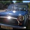
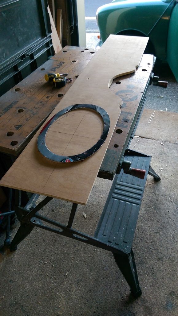
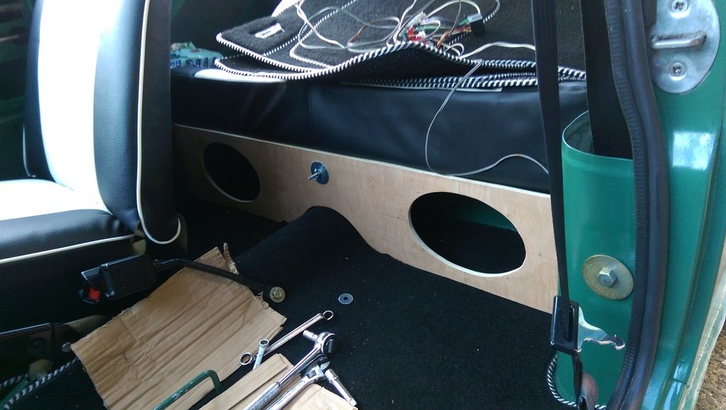
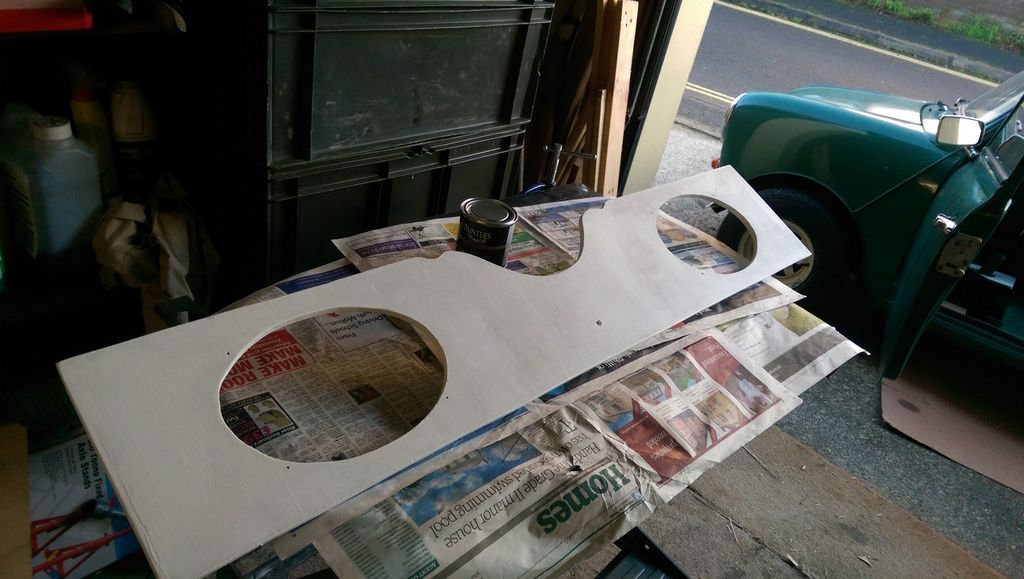
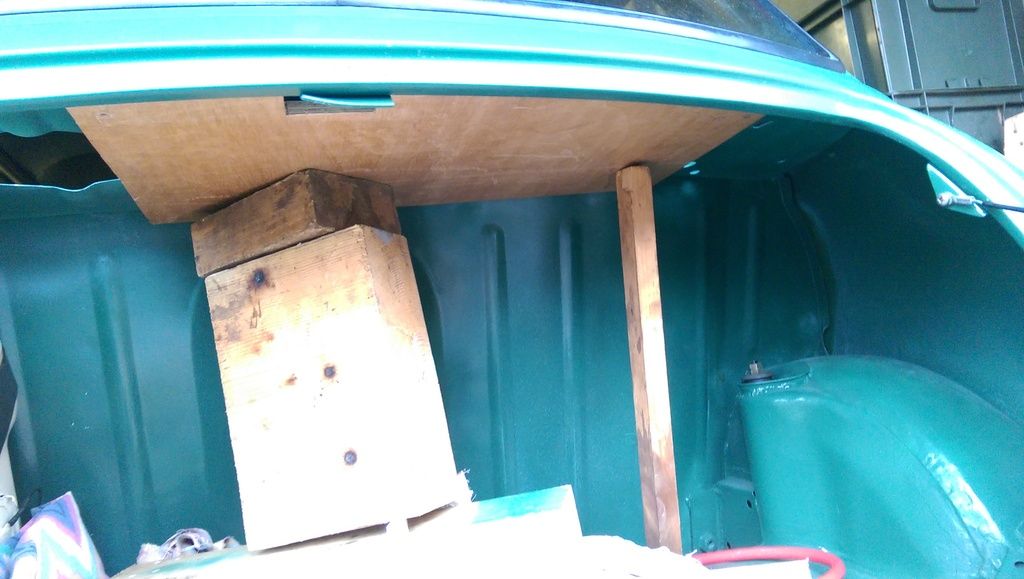
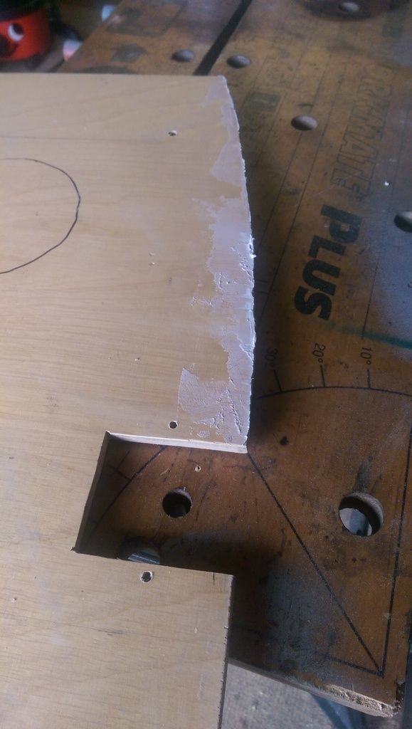
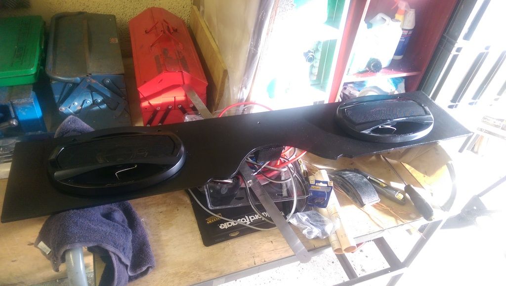
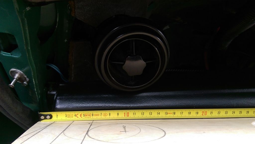
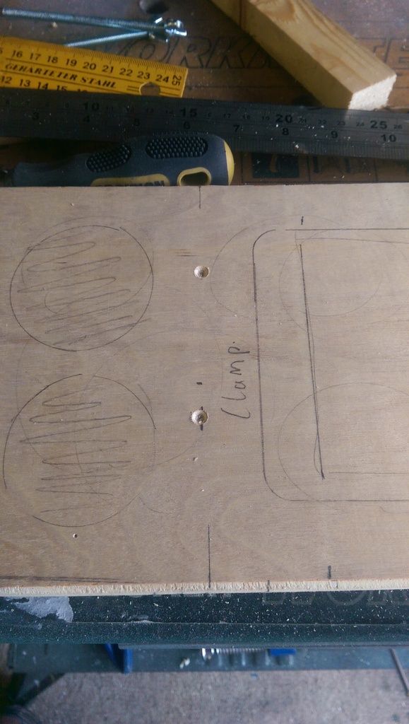
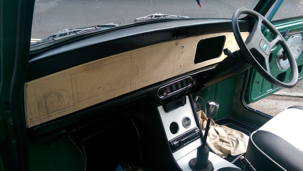
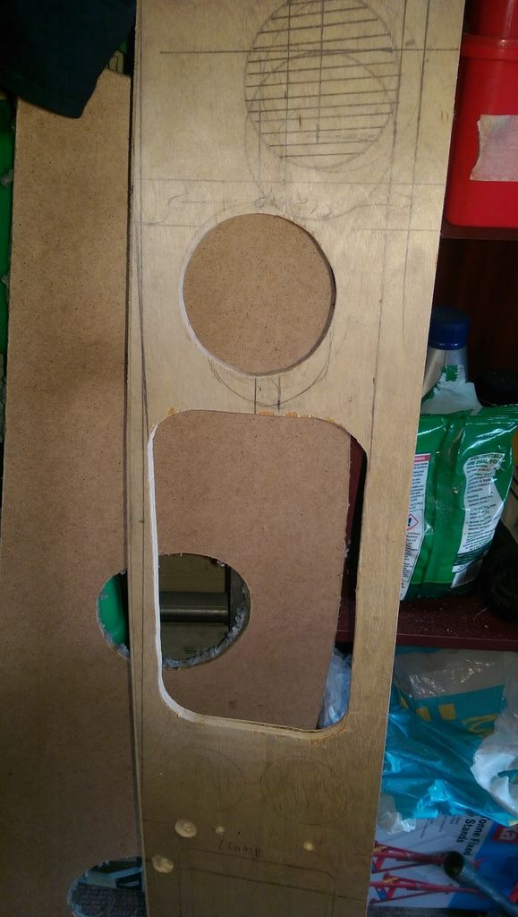
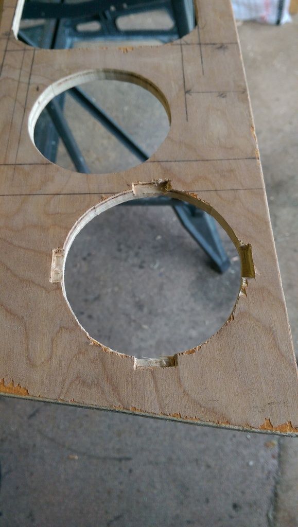
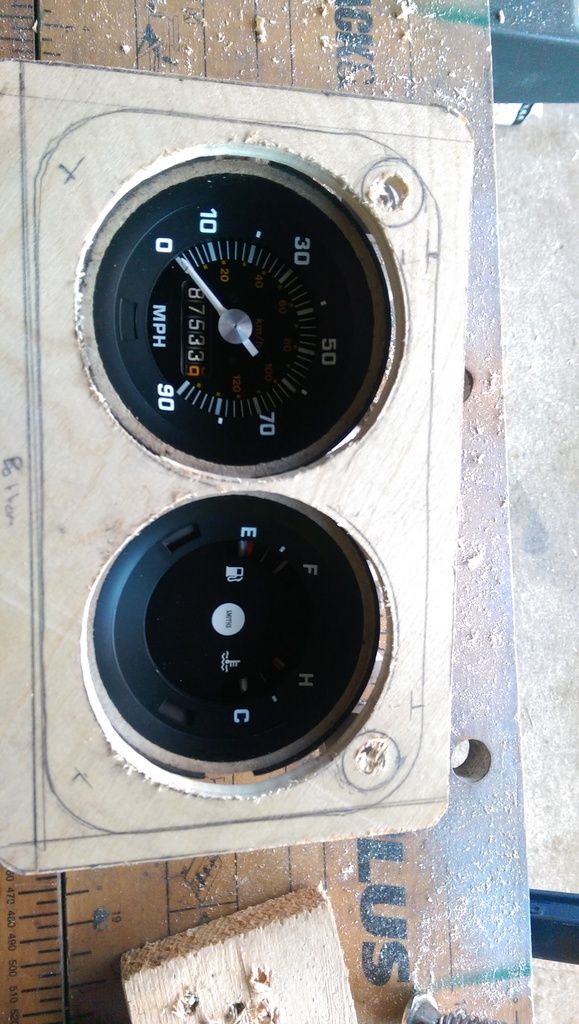
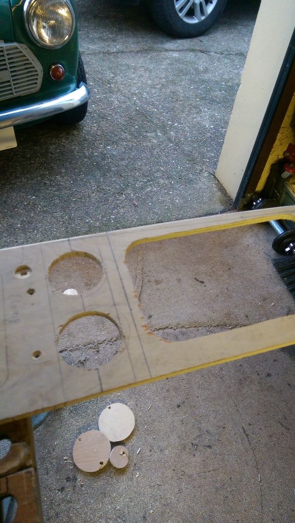
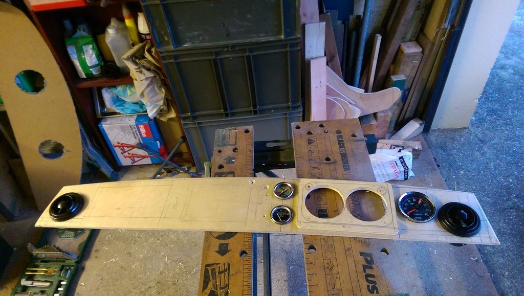
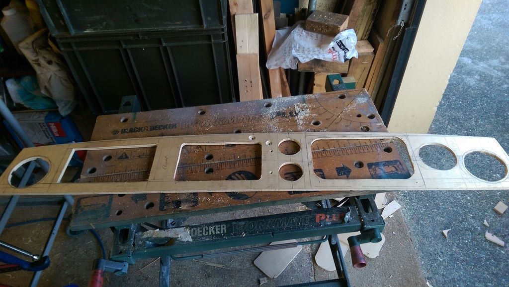
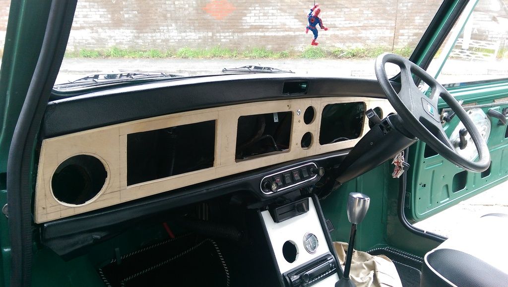
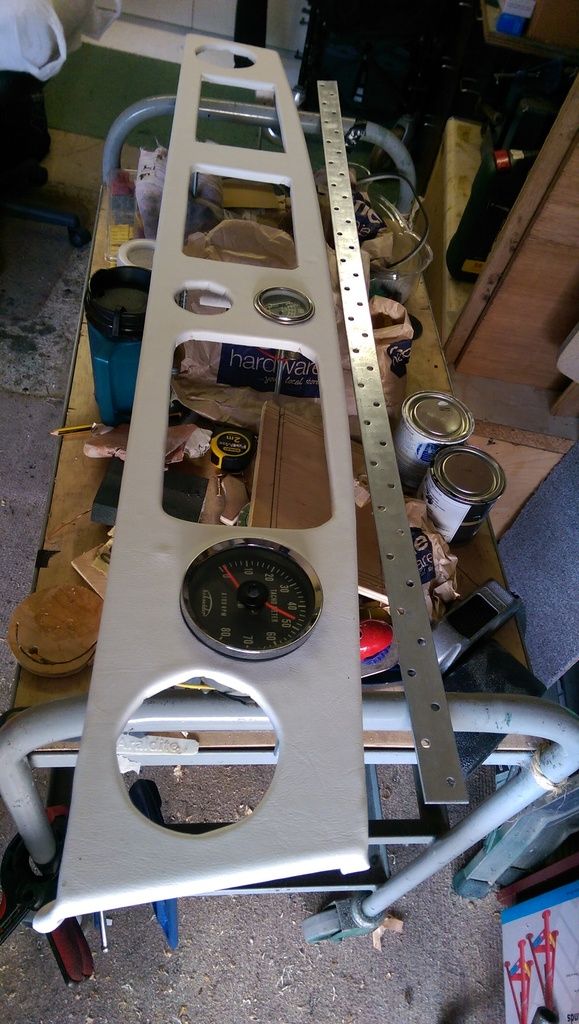
After cutting out all of the holes a test fit:


IMAG7672_zpsu8g7jrfg.jpg


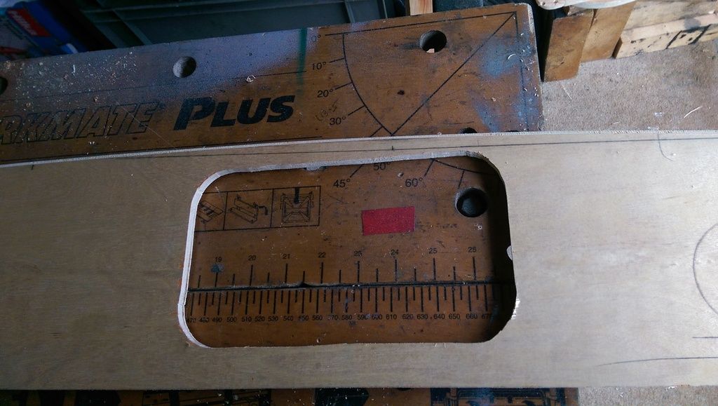
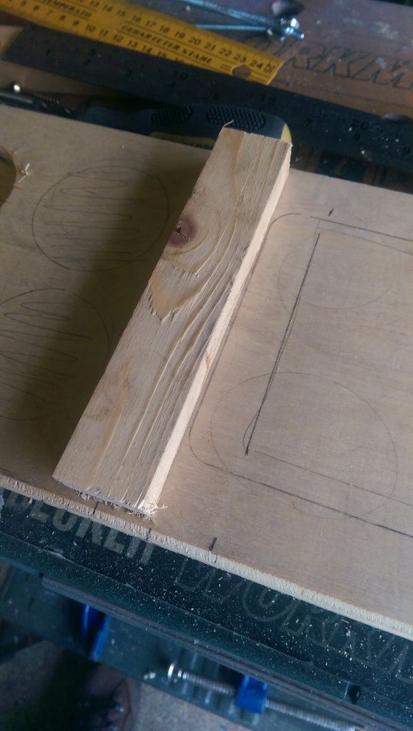
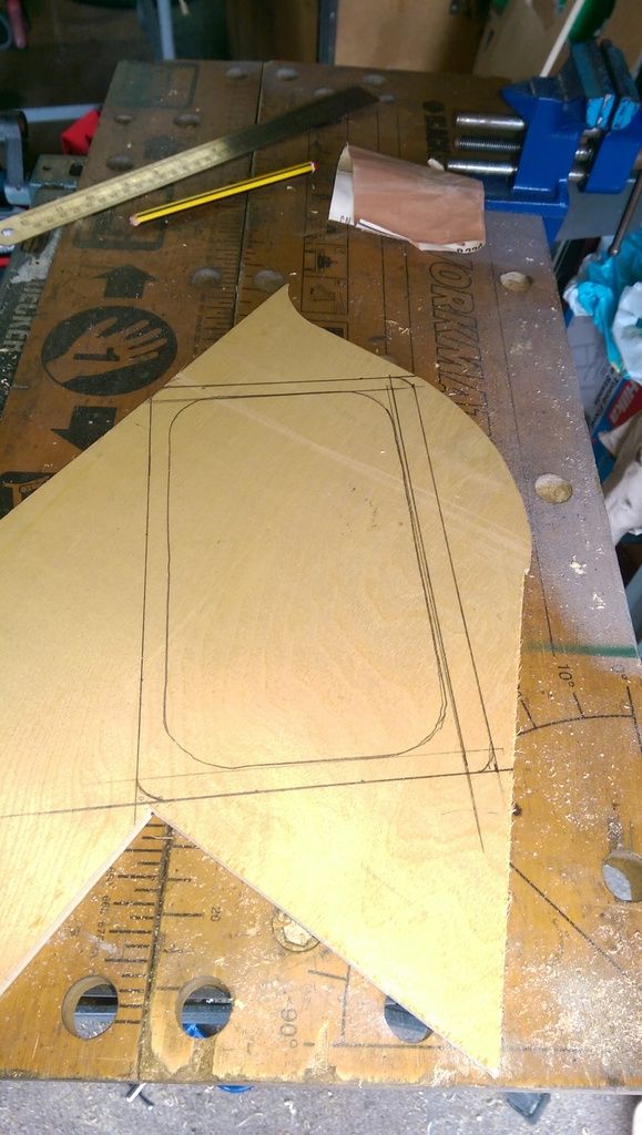
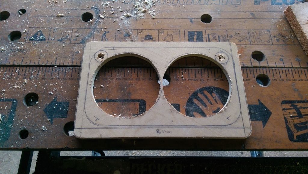
Here's the centre upper bracket:


IMAG7675_zps5h8xzn7h.jpg


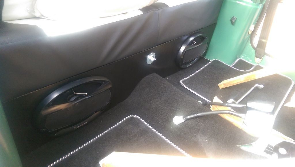
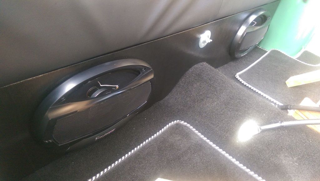
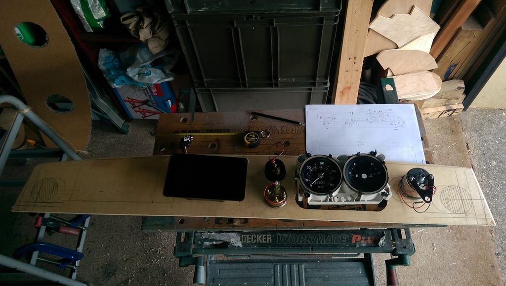
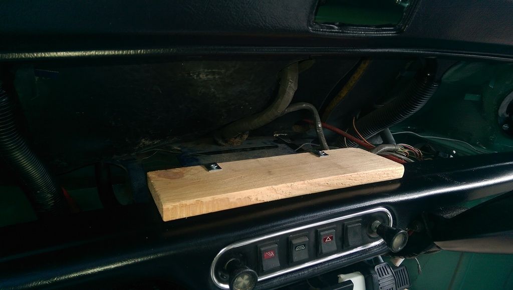
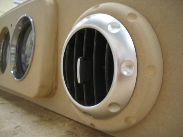
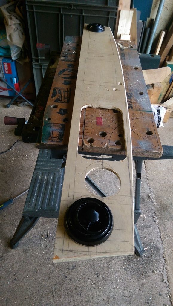
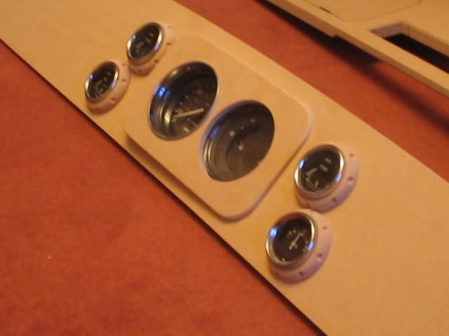
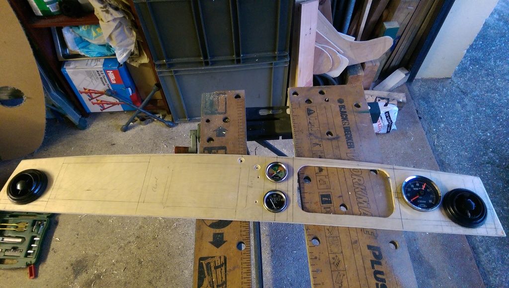
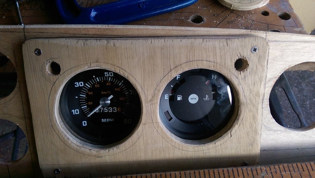
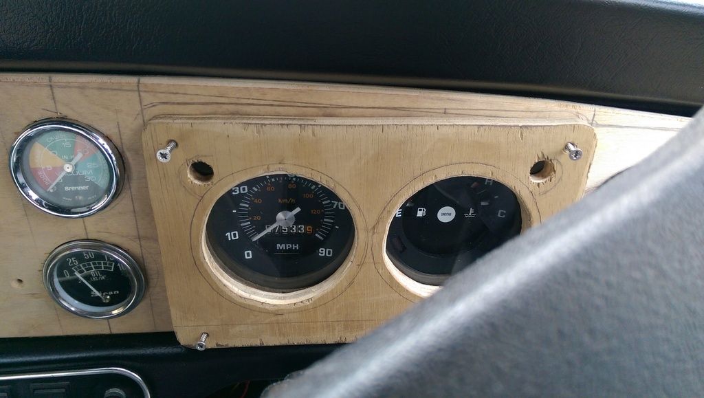
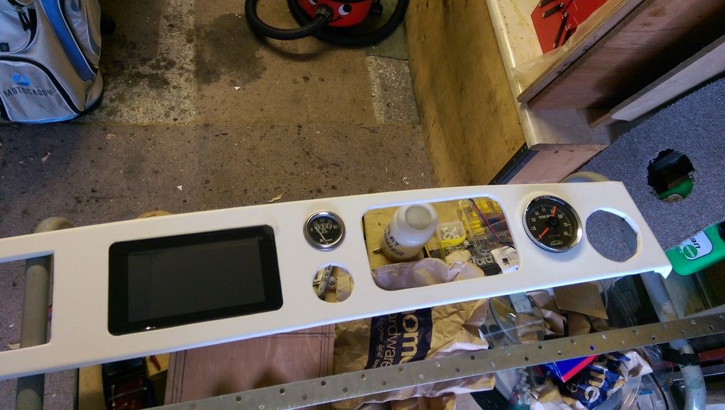
Then a trial fit with the Air Vents and Instruments:


IMAG7676_zpsb8arrg1i.jpg


I need to do more work on the main Instrument Panel. I am not sure whether to cover it in vinyl, try and make a stainless facia, or get something to rim the gauges? It also needs raising at the bottom to help viewing the instruments.

I am also not 100% sure how I will fix it in place. It needs to be removeable without removing the dash. It would make sense to screw it on with some nice screws and surrounds? Or clip it in somehow?


IMAG7677_zpsacxijtl3.jpg


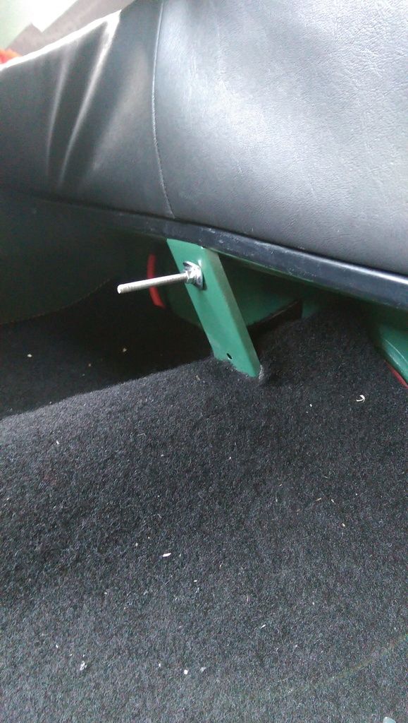
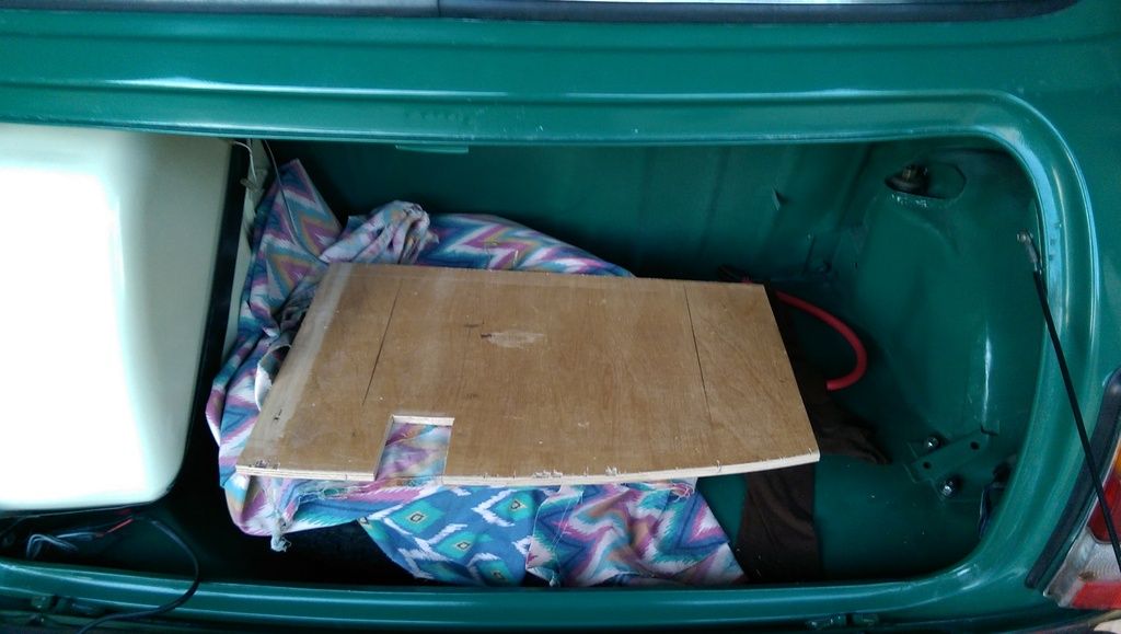
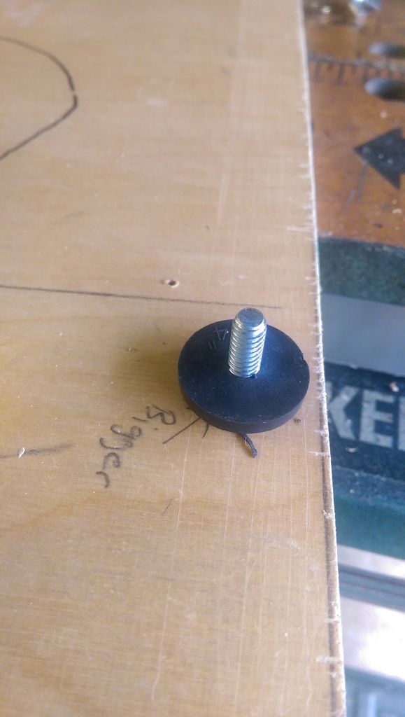
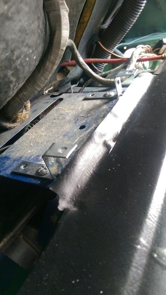
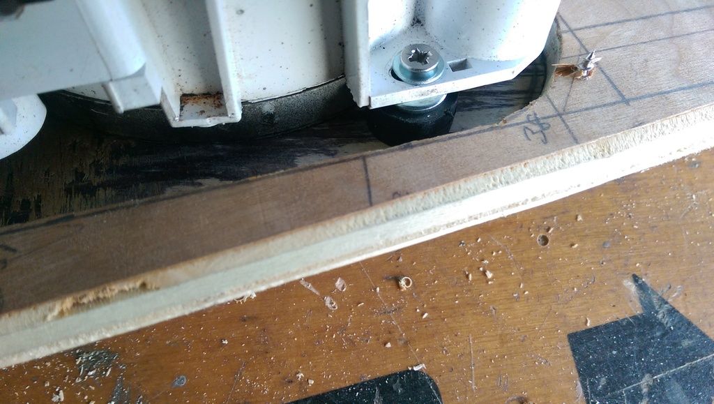
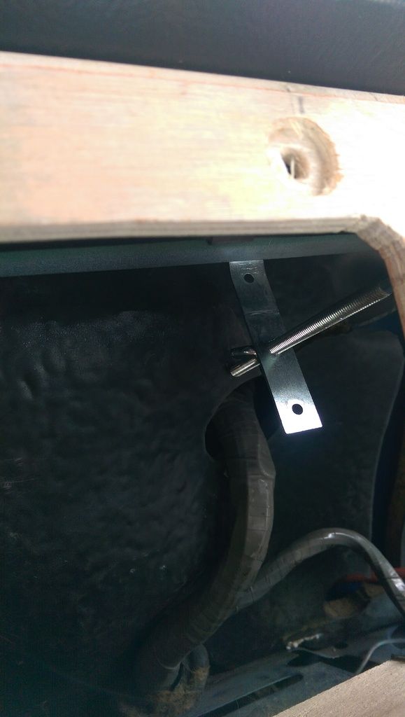
For the lower section, rather than trying to clamp it and pull it up against the lower dash I decided to extend my bottom butting piece of wood and fit some angle brackets:


IMAG7679_zpsuf5nkw2n.jpg


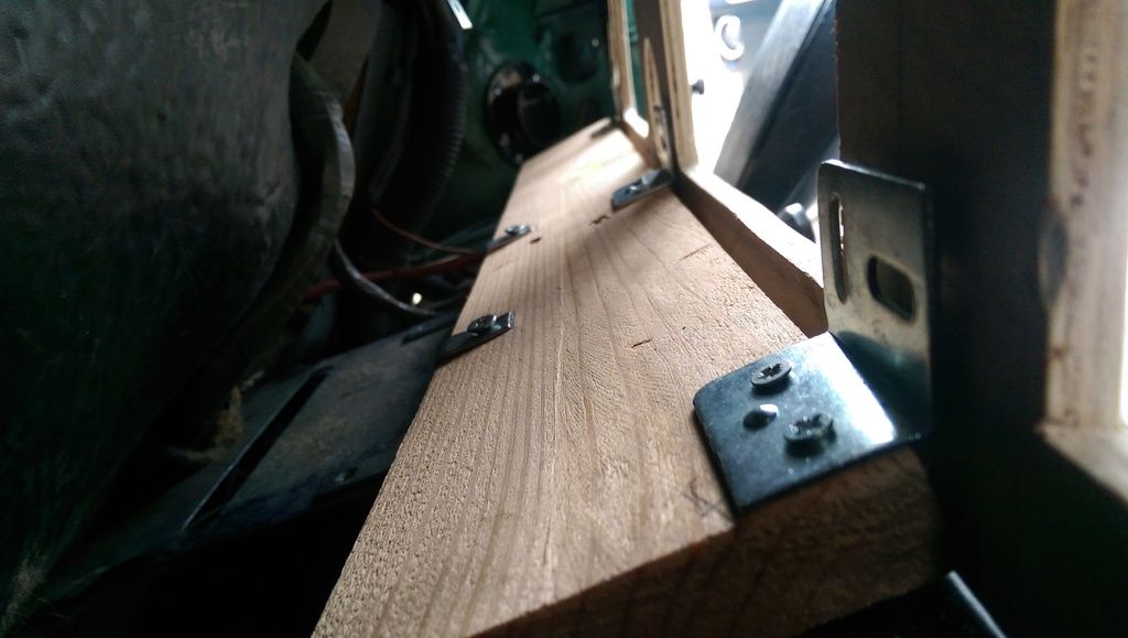
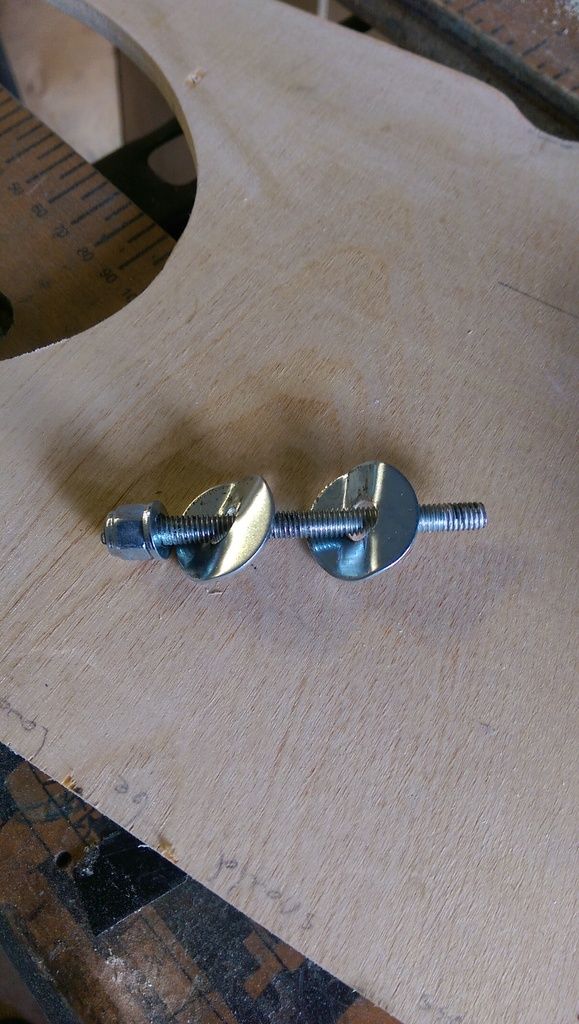
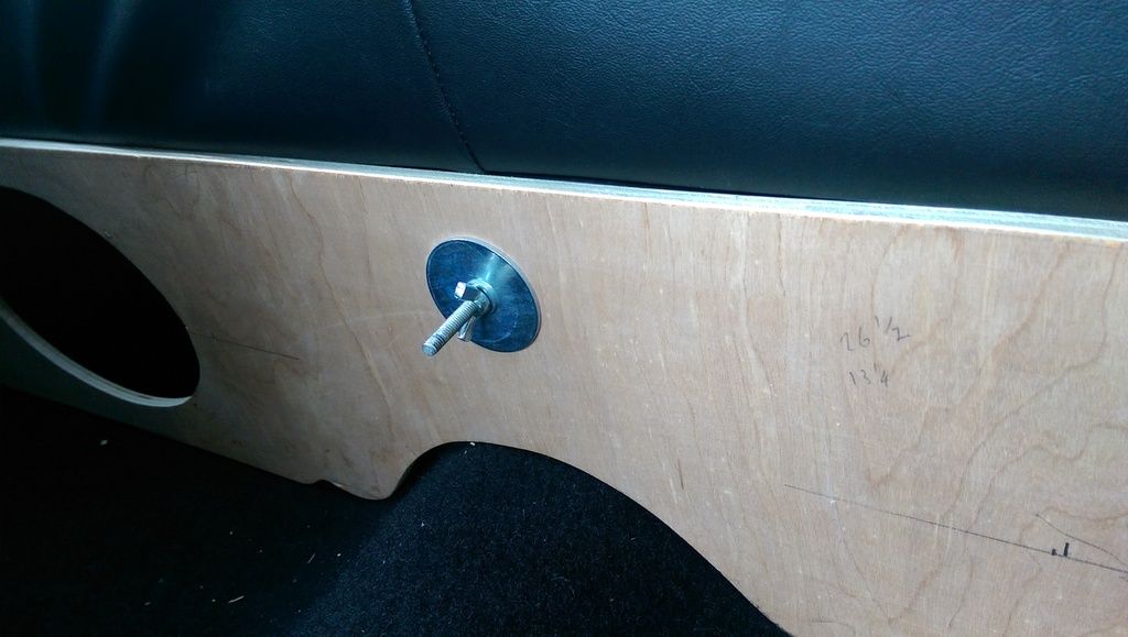
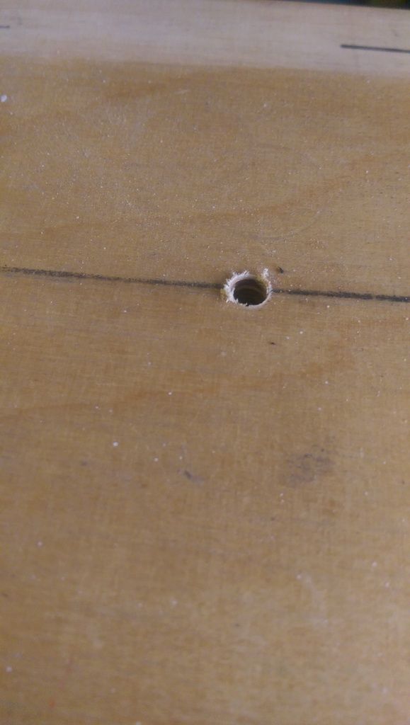
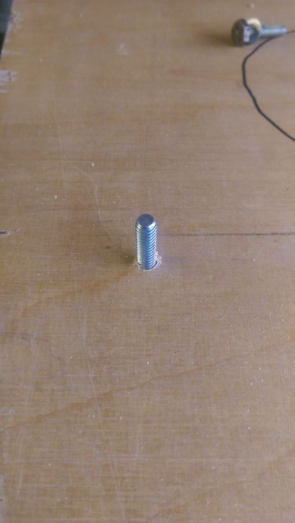
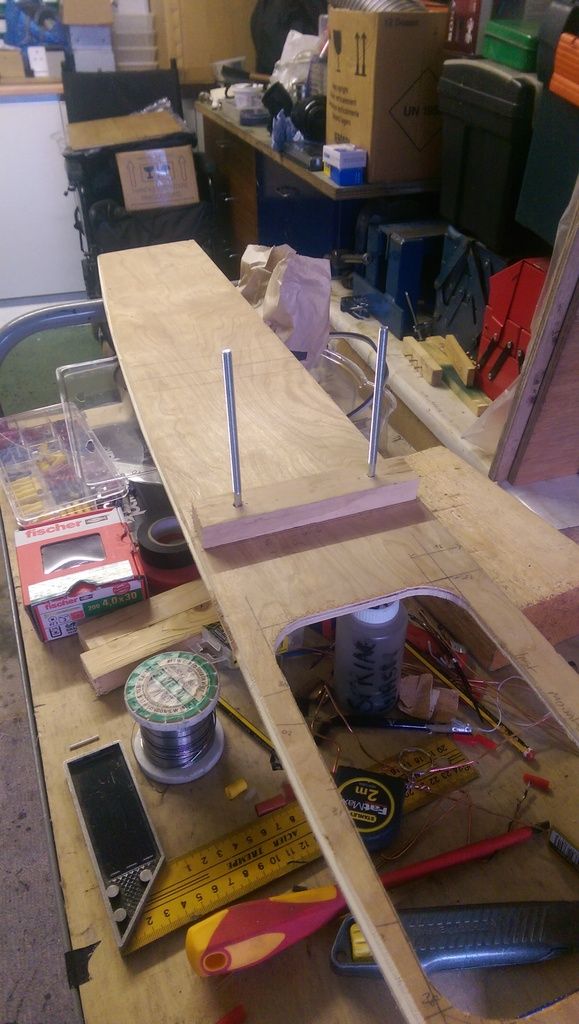
Once I marked where these brackets butted up against the dash I then drilled holes and fitted some 50mm Coach Bolts through the dash that will bolt to the brackets above.

These bolts where glued in place with Aradite. I also fitted some longer Coach Bolts at either end of the top of the dash to clamp onto the upper dash rail.


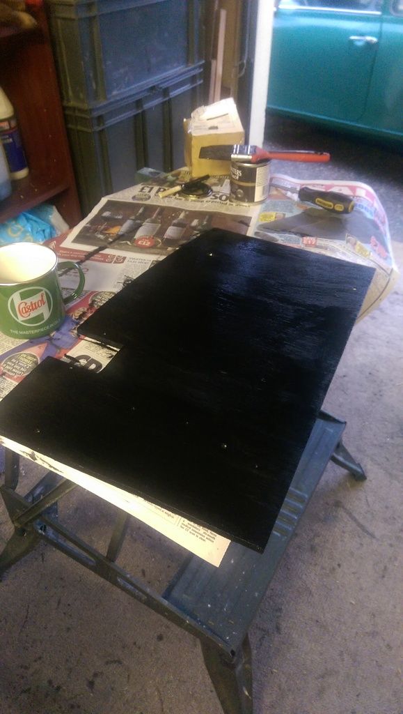
I gave the dash a lick of primer and then proceeded to cover it with white leatherette:


IMAG7685_zpsbufhexe4.jpg


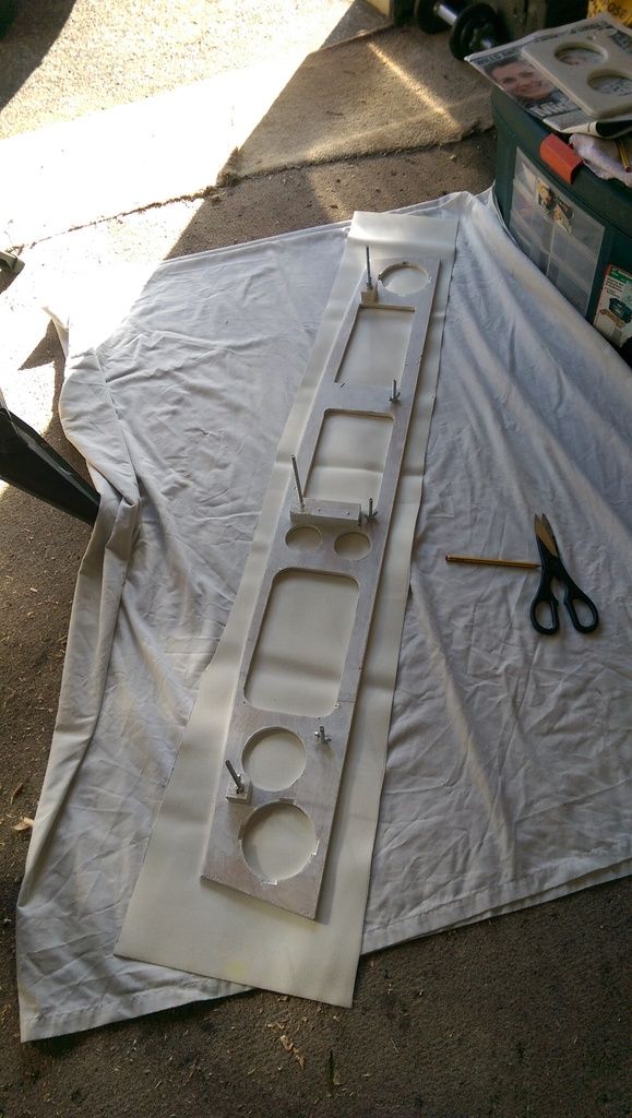
I forgot to stretch the leatherette as it had some folds but it turned out OK.


I didn't have any Impact Adhesive so I used some spray on carpet glue? Seemed OK. I also ran out of staples!!!

Once I had glued on the front and sides I cut and folded the instrument holes:


IMAG7687_zps4rw3lrzj.jpg


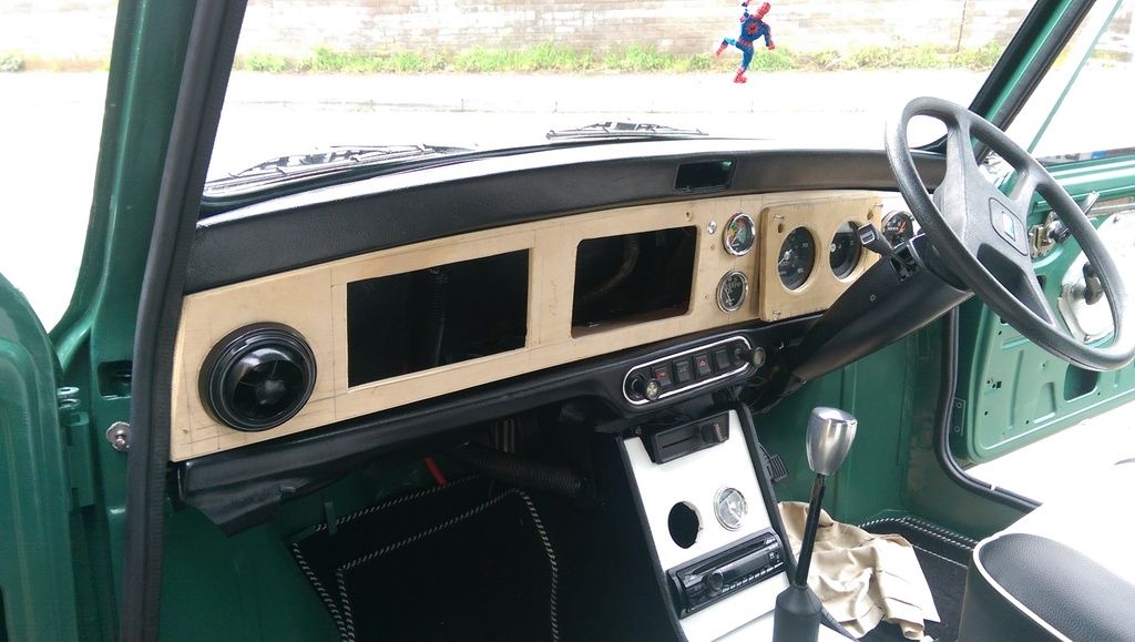
Not done the corners yet as they need to be stapled, but in with some instruments:


IMAG7690_zpsu8dlvggl.jpg


After trimming the ends of of them I also fitted the Air Vents but forgot to get a pic. I did however test fit the touchscreen In Car Entertainment PC that I am building:


IMAG7692_zpsm4uxrkwd.jpg


IMAG7693_zps21vmpm95.jpg


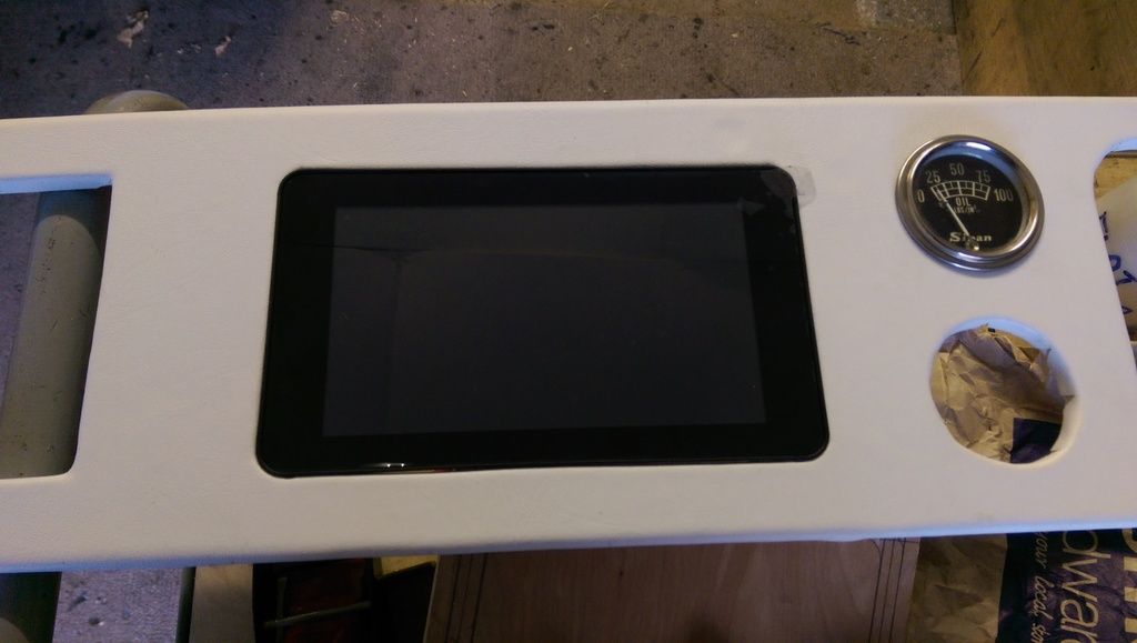
I was going to make a facia for the touch screen but it looks OK without?


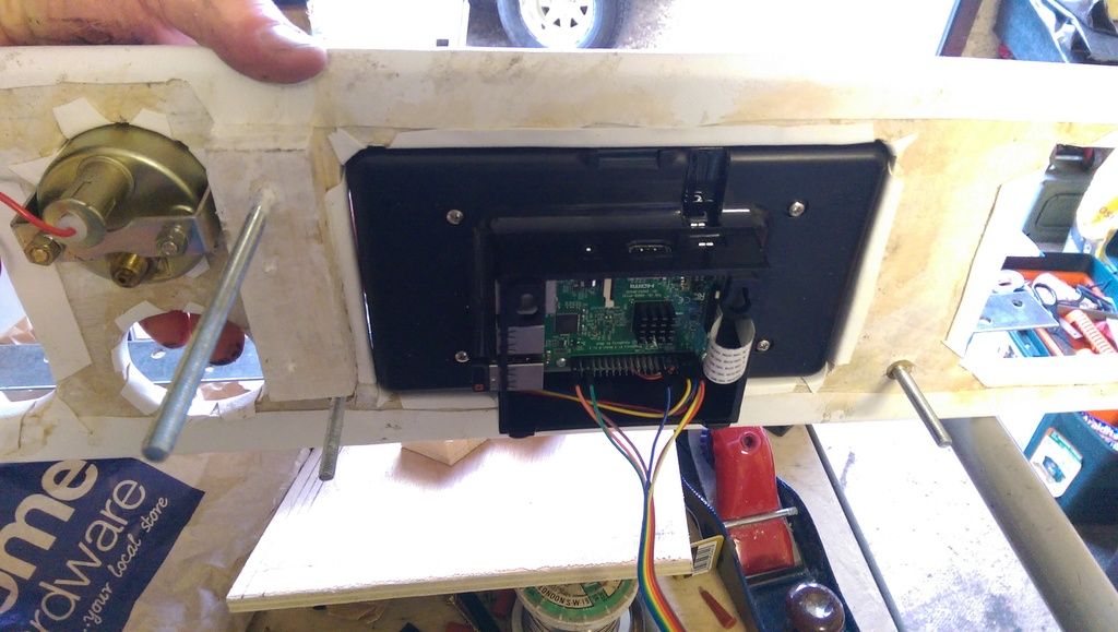
It fits snug but I am not sure how to fix it yet? It needs something on the back to (a) stop it falling through and (b) to hold it in place to stop it falling back out. It also needs to be able to be removed in case it stops working and I need to repair it (wires loose, re burn the SD Card Image etc).


IMAG7694_zpsz93wkngm.jpg


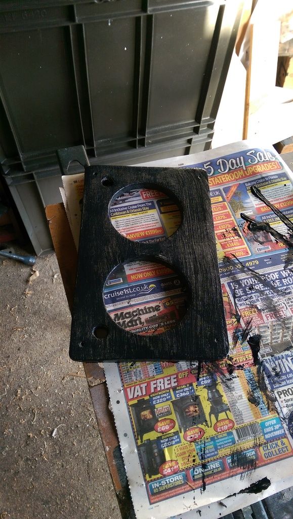
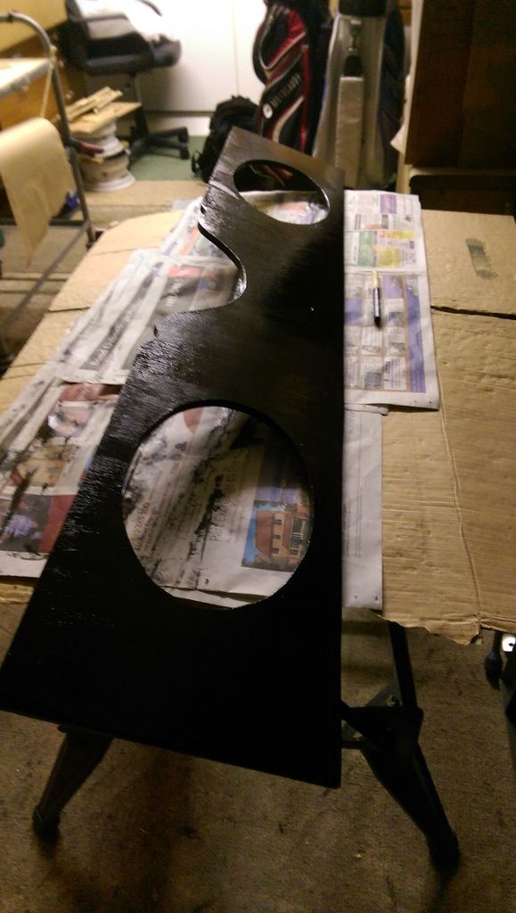
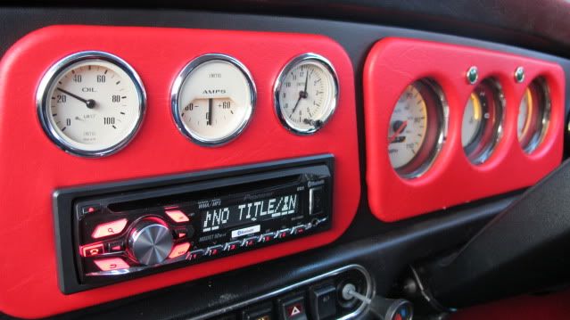
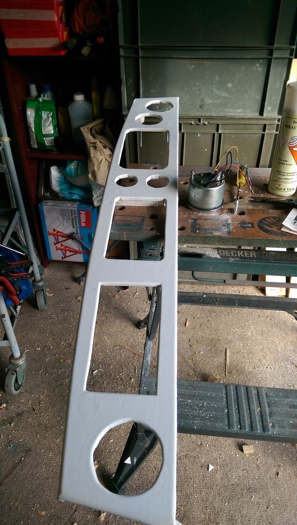
As a temporary measure I painted the main Instrument Facia (ugly):


IMAG7691_zpslueeex0h.jpg


#645 panky

panky

    Camshaft & Stage Two Head

  • Members
  • PipPipPipPipPipPipPipPip
  • 1,776 posts
  • Location: Cheshire
  • Local Club: Northwest Casual Classics

Posted 15 February 2017 - 10:59 PM

That's looking really good, well done that man :D


1 user(s) are reading this topic

0 members, 0 guests, 0 anonymous users


    Bing (1)