Jump to content


Photo

4 Injector Mpi Manifold


  • Please log in to reply
15 replies to this topic

#1 Dylan8660

Dylan8660

    Mini Mad

  • Members
  • PipPipPipPip
  • 206 posts
  • Location: Drogheda, Ireland

Posted 18 March 2012 - 02:05 PM

Apologies if this seems a little fractured in places but please stick with it.

Quiet some time ago I noticed that in the mpi-wiring diagram, four wires control the two injectors. I wondered if these were individually controlled and could they be exploited by running a four-injector manifold and whether there’d be any benefit in doing so.


Attached File  wiring diagram.bmp   750.05K   79 downloads

Fig1 – wiring diagram
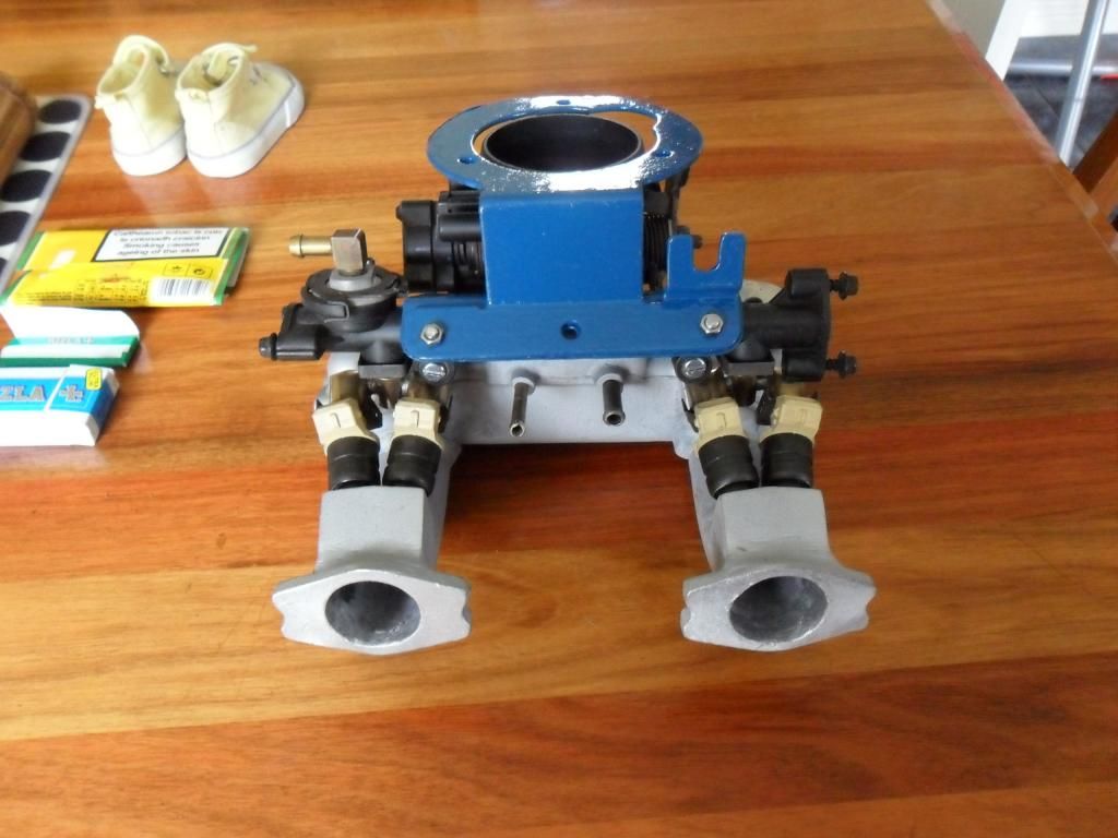
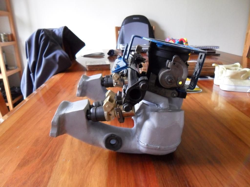
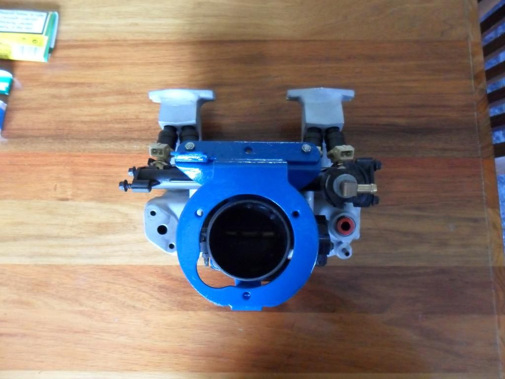

So I built this:


Attached File  SAM_1707.JPG   2.25MB   154 downloads

Fig2 - manifold build


What I was hoping for from this manifold with its directed injectors was better fuel distribution resulting in better mpg and power. As the ecu fires sequentially and fuel is delivered only when the valve is open it is possible that a venturi effect between the air and fuel may also be of some benefit even though the drawn fluid would change as the revs rise, but either way it had to be a good thing. A couple of e-mails to Mike Theaker, who was kind enough to entertain me, ensured that the right injector was firing at the right valve. He also gave an opinion on a diagram I made to ensure that my thinking on how the mpi injectors fire was correct, it wasn’t, but more on that later. The pin out for the MEMS 2J ecu turned out to be straight forward, On the red connector

B12 injector 1
B13 injector 2
B14 Injector 3
B35 Injector 4


The way an mpi fires its injectors is this:


Attached File  Std mpi injection.bmp   587.54K   91 downloads

Fig 3 - mpi injector pulse


Ok so it’s a bit more complicated than that, the start/stop moves around a little according to the map but it is the basic idea. As an aside, if I were to design an efi system I’d seriously look into the potential of using venturi from the injectors to pressurise the valve chamber prior to opening, and as they’d be firing anyway you might get some boost for free. A bit like this:


Attached File  venturi injection.bmp   475.28K   56 downloads


Fig 4 – venturi boost

And it ran with four individually controlled injectors


Although it ran and I kept the manifold on for over a thousand miles it wasn’t without problems. The low rev, low load running that you get around town and in traffic was terrible. It felt as if it was choking and not properly running on all four and would stall quite often on pick up after the revs had dropped off but out on a clear road (which thankfully my commute is full of) and once it was over 2500 and especially over 3000 rpm it pulled like a train. I reckon it took a second off the 0-60 time as it was easily under 10 on every try. The fuel consumption was down by a couple of mpg but that may have been me as the throttle was very, very moreish. More research into the mpi turned up this http://www.davecoxon.../FIXED_DATA.ppt from this thread in turbo minis http://www.turbomini...p=vt&tid=171104 . With the injector firing retarded from tdc it looks like the charge robbing properties of siamese ports are being utilised but for me it could mean that the outside chambers were getting the majority of fuel lower down the rev range and not until it moves towards tdc did things equal out a bit. The graph and my experience certainly have similarities. In the graph it seems that the pulse isn’t always separate until after 2200 rpm. Now I’m only a bloke in a shed with a black and decker but I tried to answer this by hooking up LEDs to the injectors, videoing it and slowing down the playback to see if they were all firing through the range, not conclusive but an indication.


I now wonder whether a cross flow head could be fuelled by the standard mpi ecu? More research needs to be done before that’s answered, I’d need to know that there are four pulses across the whole of the rev range under all loads and if opposing pulses are equal, from the times given on page 36 they might not be. I’m thinking of getting one of these http://www.ebay.co.u...984.m1423.l2649 but I don’t know if it’ll give me accurate enough data, opinions are welcome.
In the meantime I’m re-designing the manifold so that the injector angles are brought in a little and hopefully solve the poor running as I don’t want to live without four injectors, it just feels asthmatic since I put my old manifold back on.

Now about that incorrect diagram I mentioned earlier. From reading about the way the mpi works with its bi-directional pulse width stretching from a definite start and end point and with my four injectors in mind I drew this.


Attached File  my mpi injection.bmp   628.24K   48 downloads


Fig 5 – my four-injector theory


Working like this

Attached File  under load.bmp   1.14MB   40 downloads


Fig 6 – under load


This wouldn’t work with the mpis two injectors as there just isn’t time in the cycle to have that much control but, and it took me a little while to realise it. With four injectors it could be done and the duty cycle per injector is theoretically doubled to 50% when the pulses overlap to each other’s fixed point. With the current 460cc/min injectors that, according to various online calculators, is good for over 170bhp. Fat chance from a n/a 1275 mpi but it would give you the option of smaller injectors for better idle and fuel control with none of the starvation issues or power restrictions. This theory might be of use to those forced induction mini owners looking for an answer to fuel injecting high power motors. I know my theory is simplistic at best and there are advance, retarding and degree control problems but I just thought I’d throw it out there as I certainly don’t possess the knowledge, tools or talent to take it further. If it is feasible and you can make a plug and play ecu for the mpi mini running this theory I have the manifold to suit.
Dylan8660.

Edited by Dylan8660, 18 March 2012 - 02:11 PM.


#2 nev_payne

nev_payne

    Up Into Fourth

  • Members
  • PipPipPipPipPipPipPipPipPip
  • 2,249 posts
  • Location: UK

Posted 18 March 2012 - 02:51 PM

First I have to say that one hell of a piece of work. Makes sense as the MEMS was built with the K-Series in mind, hence the spark in each cylinder on an exhaust stroke, amongst other things.

Did you get to the the bottom of low-RPM problems? Could of us have had problems exactly as you descibed, due to the IACV being grubby and not sending enough air through, crankcase pressure, and breather hoses being blocked. Worth looking into?

Edited by nev_payne, 18 March 2012 - 02:52 PM.


#3 Dylan8660

Dylan8660

    Mini Mad

  • Members
  • PipPipPipPip
  • 206 posts
  • Location: Drogheda, Ireland

Posted 10 April 2012 - 05:41 PM

I've been looking into how the injection method I want might be achievable through the use of a piggy-back system to the ecu, and thinking about what I would need it to do to alter the injection timing, make sense of the mpi’s sensors and flywheel so that a spec can be drawn up. But it occurred to me that because of the fuel injector event retarding due to fuel transport that the answer may already be in the mpi’s ecu. I think if I changed the way it is wired namely injector 1 & 4 serving cylinders 1 & 2 and injectors 2 & 3 serving cylinders 3 & 4 I might very well get exactly what I’m looking for.
I will really need to put it on an oscilloscope to be definite about the order of injector firing but it could be that the solution to the mpi fuelling limit is the mpi itself. I’ll give it a lash this weekend, watch this space.

Edited by Dylan8660, 10 April 2012 - 05:44 PM.


#4 phil242

phil242

    Stage One Kit Fitted

  • Noobies
  • PipPipPip
  • 86 posts
  • Location: France
  • Local Club: Mini Maniac Alpin

Posted 05 May 2012 - 08:54 PM

Hi Dylan8660,

Really impressive guess & work !

Hope to follow soon your adventures ;-)


Another way to hack the MEMS is to look inside the original ECU code. By past I have start look inside the EPROM, and it's a Motorola CPU, IDA-PRO software allow you to handle it.

After, I don't know if it's possible or not to achive modification & run it to see the results. People tuning modern ECU do it, so my guess is that it's possible on those old ECU too with extra hardware as EPROM emulator.

Phil

#5 nev_payne

nev_payne

    Up Into Fourth

  • Members
  • PipPipPipPipPipPipPipPipPip
  • 2,249 posts
  • Location: UK

Posted 06 May 2012 - 12:41 PM

Would be really sweet if you have more historical photos, if you wrote up a project page about how you built it and what problems you faced etc. . There'd be quite the interested crowd for sure, in any case keep us posted :)

#6 Dylan8660

Dylan8660

    Mini Mad

  • Members
  • PipPipPipPip
  • 206 posts
  • Location: Drogheda, Ireland

Posted 06 May 2012 - 01:40 PM

Thanks Phil/Nev,
The initial results of trialing the theory are quite positive, at a recent event it happily kept pace with well built 1330 and 1380 carb'ed minis, not bad for a well used 1275 mpi with nearly 80k. Only the comedy wet weather handling of the 175 tyres on sportpack fashion wheels let me down, leaving me to really look forward to making the full switch to 165/55/R13 which I find quieter, more comfortable, more forgiving of road/geometery imperfections, give lighter steering and just work better.
Of course there are new problems and questions that need answered but the summer months should provide time for those. What I'm hoping for at the end of this journey is a fairly simple modernisation that any spanner weilding mpi owner (me) could do in an afternoon given the right parts and direction. So for that I want to keep the ecu standard for now but useful info all the same. When I'm done I might even put up a build diary.
Cheers.

#7 jamesmpi

jamesmpi

    Camshaft & Stage Two Head

  • Members
  • PipPipPipPipPipPipPipPip
  • 1,940 posts
  • Location: Chichester
  • Local Club: Abingdon Mini Owners Club

Posted 06 May 2012 - 03:02 PM

What I'm hoping for at the end of this journey is a fairly simple modernisation that any spanner weilding mpi owner (me) could do in an afternoon given the right parts and direction. So for that I want to keep the ecu standard for now but useful info all the same. When I'm done I might even put up a build diary.
Cheers.


I'll be very interested in this. I've got a 1380mpi which struggles with the standard ECU. Ive always wanted to explore the option of a better fuel injection setup that can be taylored for higher capacity engines.

#8 sweetytp

sweetytp

    Just On Tickover

  • Noobies
  • Pip
  • 6 posts
  • Location: Thessaloniki

Posted 24 December 2012 - 09:15 AM

Hmmm... So the 4 injector LPG sequential kit I am going to equipe the General with, could do exactly that! It has it's own ECU working in parallel with the standard one, and I could temper with the settings. Quite interesting I 'd say...! Will let you know on how things will turn out. Thanks

#9 shough

shough

    Mini Mad

  • Members
  • PipPipPipPip
  • 196 posts
  • Location: Surrey
  • Local Club: N/A

Posted 24 December 2012 - 01:18 PM

This is interesting, has any more come of it Dylan8660?

#10 Dylan8660

Dylan8660

    Mini Mad

  • Members
  • PipPipPipPip
  • 206 posts
  • Location: Drogheda, Ireland

Posted 24 December 2012 - 06:41 PM

There is a bit more to the story yet, I should have a liitle time to write it up over the next couple of weeks.

Sweetytp, I'd like to here more about your LPG conversion as I'm sure it'll be a gas to fit............sorry couldn't resist.

#11 jamesmpi

jamesmpi

    Camshaft & Stage Two Head

  • Members
  • PipPipPipPipPipPipPipPip
  • 1,940 posts
  • Location: Chichester
  • Local Club: Abingdon Mini Owners Club

Posted 26 December 2012 - 08:29 PM

Oooo cant wait!

#12 Dylan8660

Dylan8660

    Mini Mad

  • Members
  • PipPipPipPip
  • 206 posts
  • Location: Drogheda, Ireland

Posted 31 December 2012 - 07:36 PM

Well I went away and rebuilt the manifold and fuel rail to further test the theory, I sourced some 330cc/min high impedance injectors that come from a bini cooper s, the irony of finding something of use from that type of car amused me. The injectors are shorter than the Lucas ones that are standard on the mini which made the fitting of them a tad easier. This is what I ended up with:

Posted Image

Posted Image

Posted Image


The reasoning behind the sizing of the injectors was to find some that would necessitate the pulses to overlap in order to run properly but not so much that the overlap would have to be constant so that in normal light load it would fire as any sequential system but under high load it would assume the characteristics of staged injection, Semi-Staged injection if you like. From the online injector size calculators, to produce the standard 63bhp the 460cc/min injectors have a duty cycle of 18%, for 85bhp (probably the maximum a n/a stage 3 mpi without a pbv could achieve) the duty cycle is 24.3%, using 330cc/min injectors a 63bhp duty cycle is 25% and 85bhp is 33.8%.

So by tuning our minis the traditional way through better flow we are increasing the duty cycle by 35%, but achieving the same from 330cc/min injectors the duty cycle has to be increased by 87.7%. The question now is whether the ecu will comply with being forced to increase the duty cycle by that amount. To give a bit of extra background to this theory the ecu of any modern car will increase duty cycle in order to cope with circumstance and environment for example a drop in fuel rail pressure, so I never felt that doing this was beyond comprehension but was unsure of built in limits and safety factors.

The manifold was fitted and plugged in, not without its problems as altering the angle the fuel rail was fitted gave trouble with the return feed and vacuum pipe to the fpr. I can only apologise that no photos or videos were taken of it fitted and running I was in-between phones at the time and the convenience was not there. So it did run and on the driveway it revved well, very well but out on the road it was awful, fuel starved and lacking power. I checked everything and had several attempts to get it running well but unfortunately it was not to be.

The conclusions I can reach from these experiments are that there is a built in safety factor with the mpi ecu, it is there for good reason because if the duty cycle could extend beyond that of a valve event then in its standard form the inner cylinders would run very rich. This is the limiting factor of the factory ecu and if it was possible to re-map it in terms of duty cycle then a dangerous running situation could easily be entered into. I still have upmost respect for the designers of the mpi system and the ingenuity and forethought they’ve shown, I do however feel that my theory of Semi-Staged injection is a viable method of injecting Siamese ports and one that if production and development had continued, could have solved the idle/emissions/power conundrum.

So where does this leave me in terms of getting the most from my mpi, well as the pulses don’t overlap I can wire the standard two injector set up in the same way as the four injector manifold and the system will be more true to sequential than in current form, this can be done by swapping the red/yellow wire from pin B35 with the brown/yellow wire from pin B12 on the ecu if anyone is feeling brave (*disclaimer* in no way is this recommended, advisable or a proven method and will be at your own risk, so careful now). I will also try bigger injectors as I haven’t found any record of anybody actually trying this simple and obvious method but all this will have to wait as I have been having a few hundred quids worth of exhaust and therefore emission troubles as well as steering rack and rot patches but when I’ve got it all running properly again I’ll be trying these last few experiments before moving onto another hair-brained theory I have in the pipeline.

Happy New Year.

#13 nev_payne

nev_payne

    Up Into Fourth

  • Members
  • PipPipPipPipPipPipPipPipPip
  • 2,249 posts
  • Location: UK

Posted 03 January 2013 - 12:01 AM

More photos and any solutions you find are always welcome chap, great that you had another run to see what you could come up with :D

#14 sweetytp

sweetytp

    Just On Tickover

  • Noobies
  • Pip
  • 6 posts
  • Location: Thessaloniki

Posted 15 January 2013 - 03:17 PM

Whow Dylan!! You really went all the way with this!
So this is what I came up with:
The standard MPi ECU starts on 4 pulses but the loom bridges them into 2. This allows for the 2 injectors to work, but it also bridges the ECU, as the signal loops back to it.
The reason why on high loads you are OK, is that the A series engine is capable of consuming a lot of fuel (as the dual Webber 40 configuration proves). When you are going close to idle speeds though, the engine is choked with the amount of fuel going into it. The standard ECU cannot do what the dual carbs can when changing from the main jet to the pilot jet, even if you get the pulse down to a minimum ms setting.

For the LPG system now, they come with a 4 injector configuration. I could get the engine to run well under load, but when going under 1500rpm the no 2 and 3 cylinders where getting way too much fuel into them, resulting to auful idling.
When I had the car running on idle well, there was not any performance whatsoever under load.
So I 've set the LPG system to change over to petrol beneath 1100rpm and tuned the car to run on LPG all the way up to 6k rpm safely, using an Exhaust temp gauge.
I am now working exceptionally throughout the rev range without any problems.

Furthermore on the 4 petrol injector layout, I saw that the way the A series acceprts the mixture is actually restricting the 4 injectors, as the inlet ports are too far away from the inlet manifold for anyone to be precise.
I reccon that a 7 port manifilod in conjuction with an aftermarket blank ECU will be a real improvement. (Gains come with Pain!!!)

Hope I was helpful
Thank you very much Dylan for your efforts BRAVO!

Edited by sweetytp, 15 January 2013 - 03:55 PM.


#15 Dylan8660

Dylan8660

    Mini Mad

  • Members
  • PipPipPipPip
  • 206 posts
  • Location: Drogheda, Ireland

Posted 15 January 2013 - 07:39 PM

Thanks for the kind words sweetyp,

I'd say your right that the loom bridges the four signals to two injectors but as far as the ecu is concerned it wont know if it was four, two or one that are being used, four pins, four seperate switches to fire the pulses.

Did you, or are you running 4 injectors? I'd love to see a photo of your set up. I'm not surprised by the trouble you've had, the siamese ports must be a real juggling trick to try and set up yourself. The original idea for using four was to reduce the size (flowrate) but this really isn't possible unless the injection is staged somehow. I know they've had some success with this on www.turbominis.co.uk but I quiet like the mpi ecu and I know I can't do better so this is as far as I will go with this.

7 ports would be too easy.

Edited by Dylan8660, 15 January 2013 - 07:40 PM.


0 user(s) are reading this topic

0 members, 0 guests, 0 anonymous users