Jump to content


Photo

Help With Rear End Panels, Heelboard, Sills Etc


  • Please log in to reply
25 replies to this topic

#1 JonnyAlpha

JonnyAlpha

    Up Into Fourth

  • Members
  • PipPipPipPipPipPipPipPipPip
  • 2,744 posts
  • Location: North Devon
  • Local Club: Exmoor Minis

Posted 28 April 2014 - 12:13 AM

Hi;


I am just finishing of doing the repairs in my boot and am about to do the sills Inner and Outer and front LH floor pan.


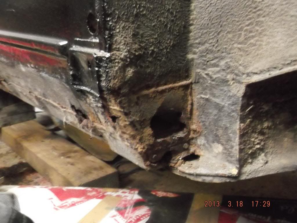
Inside the companion bin looks a right mess and is so rusted I am confused what's what, the Inner Sill Closing Plate has completely gone as has the rear arch up to and in line with the rear shock mounting point. 


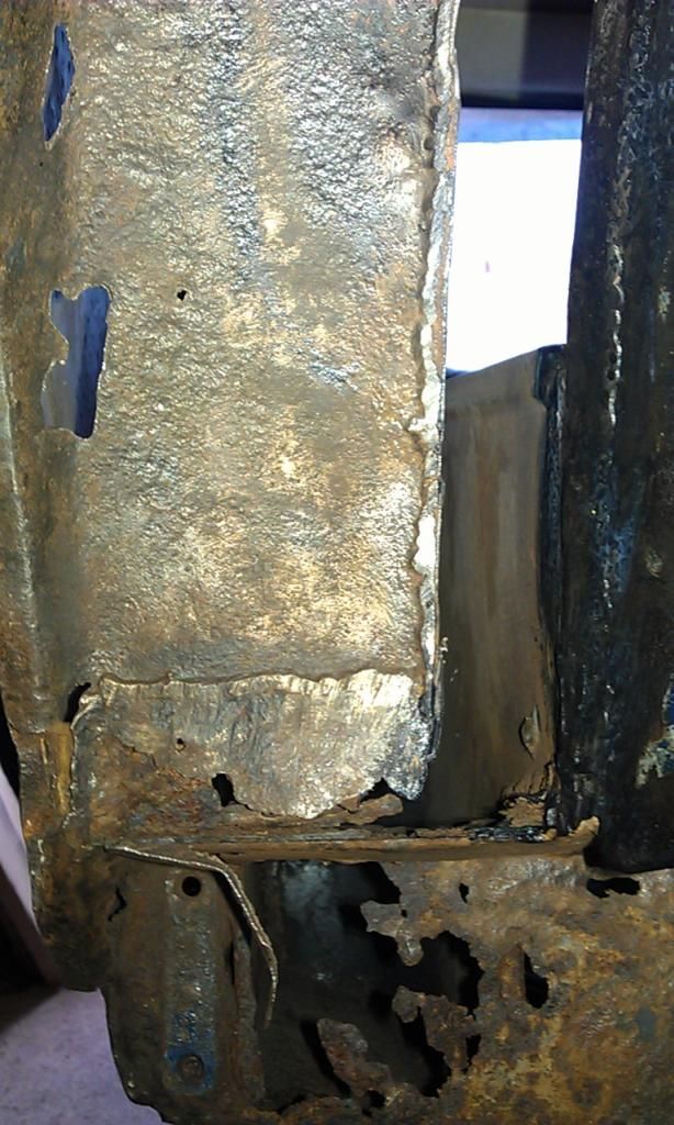
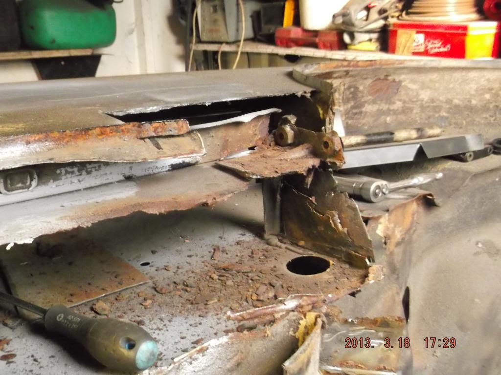
Here's the view towards the Heelboard (The gap on the RH side is where I have removed a previous repair that someone did (badly))

IMAG4873_zps9b8d2818.jpg


Here's the inside of the Companion Box looking down towards the rear:


CompanionBin_zps04090b9e.png


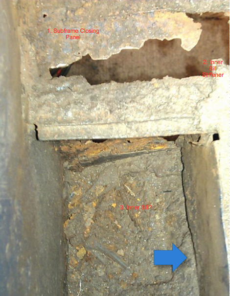
Have I identified the various parts correctly? 1. Subframe Closing Panel. 2. Inner Sill Stiffener. 3. Is this the Inner Sill or part of the floor. Blue Arrow is this the Inner Sill?


There is a piece that has rusted away that I could not identify but remembered seeing an old post here which explains that it is an Inner Sill Stiffener.


I need some help working out how to facilitate this repair, i'll number the questions to assist in tying up the responses to the questions.


1. A previous post that I put up here mentioned that I should do the Heel Board first and then the sill but that was before I realised how bad it was behind the Heel Board, if I am repairing the Rear Arch (Less Shock Mounting SIde), Heelboard, Inner Sill Stiffener, Subframe Closing Panel, Inner and Outer Sill and Front Floor Pan what order should I do them in?


2. If I cut out all the above prior to repairing will I need to brace the passenger door, if so will one piece of Angle Iron welded horizontally half way up the door or will I require some other config? 


3. Another thread I started on the Subframe Mounts and Heel Board repair here I stated that I was using Heelboard End Repairs with Captive Nuts Fitted (The ones without the Inner Sill Brackets). I was advised to fabricate a bracket or buy brackets from M-Machine, these ones:

11.32.02.27 Bracket, Rear Sub Frame Mounting with captive nuts, LH

11.32.02.28 Bracket, Rear Sub Frame Mounting with captive nuts, RH

I guess these are visible once the Sill is removed?


4. I was also advised on replacing keeping the Slinging Shoe Brackets however never found out what they where or what they looked like? 


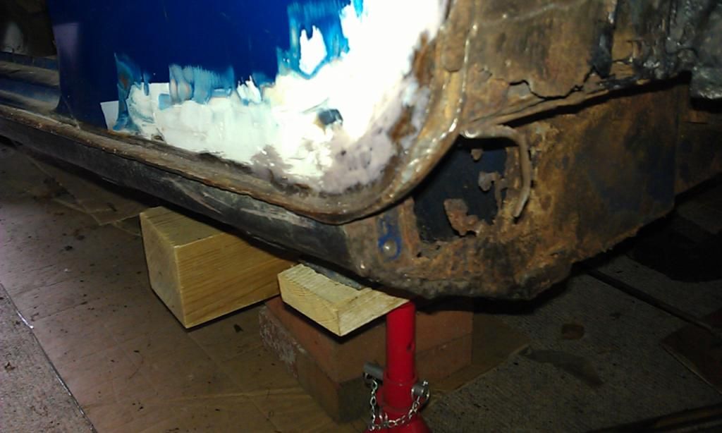
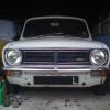
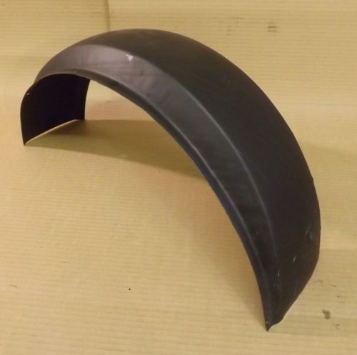
4. To facilitate the repairs to the Heelboard, Inner Sill, Outer Sill,  all the bits inside the companion bin and to get better access to weld the Rear Subframe with Captive Nut Bracket in place I will need to cut out / off the bottom half of the skin that sits below the rear passenger window, if so is this the repair panel (M-Machine 11.14.10.07 Arch to Door Repair, LH)? Or how much should I cut out? 


Here's the rear end, the part that may need to be cut out has already been filled so its probably in a state underneath??


IMAG4888_zpsc75a72f8.jpg


Thanks for reading.


#2 rally515

rally515

    Up Into Fourth

  • Members
  • PipPipPipPipPipPipPipPipPip
  • 3,848 posts
  • Location: ask!

Posted 28 April 2014 - 12:47 AM

Hi, hope these pictures from my project thread might help.


Here shows the etch primed inner sill and were it comes upto:

DSCF2588_zps0bfafbe8.jpg


And heres the stiffener rail (to the left of the shot), which joins to the closing panel, and the closing panel spot welds to the inner surface of the companion bin:

DSCF2542_zpsb73255ec.jpg

DSCF2543_zps5793a809.jpg

DSCF2544_zps3d73e250.jpg

DSCF2545_zps839800c7.jpg


And just for reference of what it looked like before :lol:  :lol: :

DSCF1315_zps9f3a7607.jpg

DSCF1316_zps3542a328.jpg


Hope these help and show what you need, if you need anymore or labeling give us a shout ;D .


Cheers,

Cliff


#3 72clubman

72clubman

    Speeding Along Now

  • Members
  • PipPipPipPipPip
  • 443 posts
  • Location: Leicestershire
  • Local Club: Charnwood Minis

Posted 28 April 2014 - 01:15 AM

Hi there, I did pretty much exactly what your describing a while back on my project. Removing the heelboard while keeping the inner sill is a right pain, and when I did it I went for the both barrels approach.  I ended up replaced the inner & outer sills, the heel board, the rear quarter, the sill strengthener, and the subframe closing panel. I used all heritage panels. Do you have oversills fitted, as these tend to get fitted over the sling brackets.


I removed the rear quarter and went from there. 


DSC_2319_zps3690aa5f.jpg


I then removed the oversills, then the inner sill as this had been damaged from oversills, then removed the strengthener and closing panel, then the end of the heel board. 

  Did a repair on the bottom of the arch, and started to reassemble.


DSC_0526_zps223ed40e.jpg


DSC_0543_zpsb7129404.jpg


DSC_0544_zps6af18196.jpg


New Subframe closing panel fitted.


DSC_0573_zps70b81859.jpg


As I'd fitted the inner sill panel the heel board just slid into the mount.


DSC_0576_zpsddf7e726.jpg


All welded in.


DSC_0591_zps75587b9c.jpg


on the ground where you can see the strengthener.


Inside once I'd fitted the rear quarter.


DSC_0643_zps940a78c4.jpg


DSC_0683_zps64e1d602.jpg


DSC_0681_zpsfa45abe8.jpg


I hope these help rather than confuse, any questions give me a shout.


Edited by 72clubman, 28 April 2014 - 01:21 AM.


#4 sonikk4

sonikk4

    Twisted Paint Polisher!!!

  • Admin
  • PipPipPipPipPipPipPipPipPipPipPip
  • 15,885 posts
  • Name: Neil
  • Location: Oxfordshire

Posted 28 April 2014 - 07:03 AM

I think all of those pictures explain everything you need. Now the slinging brkts personally I would leave off. Yes they may form a small percentage of the overall strength but just how many minis out there have had those replaced over the years??
It's down to you whether you fit the internal ones. If you are going into concourse events then the external shoes will add points to originality. Other than that they are a rust trap.

Although in the past I have binned the jacking points I would fit these as they do tie in the crossmember to the rest of the structure. I seam weld these to the inner sill as far as possible then plug weld to the outer sill.

#5 JonnyAlpha

JonnyAlpha

    Up Into Fourth

  • Members
  • PipPipPipPipPipPipPipPipPip
  • 2,744 posts
  • Location: North Devon
  • Local Club: Exmoor Minis

Posted 28 April 2014 - 01:47 PM

rally515 / 72clubman - thanks very much for the pictures they explain everything perfectly.


Sonikk4 - Ref the slinging brackets, sorry still befuddled, please confirm that these ARE NOT the Rear Subframe Mounting Support Brackets that hold the Captive Nuts and are welded to the Inner Sill and Heelboard? 

In fact I just spotted the Rear Subframe Mounting Brackets in rally515's second to last picture "Here's what it looked like before shot". I wonder why many of the replacement repair panels ommit this key strengthener? 


Looking a an image of one here  they are a different bracket altogether, is that one in 72clubman's last picture located towards the back end of the sill, looks like a nut that has been covered in paint?


Also - key question - if I am planning on cutting out the LH front floor pan Inner Sill and Outer Sill do I need to brace the front door frame with a welded bar?  


Edited by JonnyAlpha, 28 April 2014 - 01:52 PM.


#6 72clubman

72clubman

    Speeding Along Now

  • Members
  • PipPipPipPipPip
  • 443 posts
  • Location: Leicestershire
  • Local Club: Charnwood Minis

Posted 28 April 2014 - 02:12 PM

The sling brackets are mounted to the under side of the floor and were used in the factory to move the shells, I believe they serve no structural purpose. Here's a photo of a BMH shell where you can see the sling brackets being used to suspend the shell. I will be replacing my sling brackets for originality more than anything.


http://minispares.co...|Back to search


DSC01504_zps5ad7a7c7.jpg


DSC01507_zpsc7e501b9.jpg


. I bought a complete heritage heelboard and it came with the captive nuts and locating tabs. Slotted right into the inner sill bracket


Here's the panels I used, you can see the heelboard slotted into the inner & outer sill. and all the strengtheners for the inner sill.


DSC02936_zpscf0be4d6.jpg


DSC02937_zps187a9f08.jpg


The link you have is for the part you can see above, this props up the tab from the heelboard and is spot welded to the inner sill, as far as I can tell the bolt serves no purpose. It's then mig welded to the heel board tab.


As for bracing I would. Just to prevent any nasty surprises when you come to put new panels back in, especially if you're removing the front floor pans.


I hope these help. Any questions just ask.


Edited by 72clubman, 28 April 2014 - 02:34 PM.


#7 sonikk4

sonikk4

    Twisted Paint Polisher!!!

  • Admin
  • PipPipPipPipPipPipPipPipPipPipPip
  • 15,885 posts
  • Name: Neil
  • Location: Oxfordshire

Posted 28 April 2014 - 05:26 PM

I think all of those pictures explain everything you need. Now the slinging brkts personally I would leave off. Yes they may form a small percentage of the overall strength but just how many minis out there have had those replaced over the years??
It's down to you whether you fit the internal ones. If you are going into concourse events then the external shoes will add points to originality. Other than that they are a rust trap.
Although in the past I have binned the jacking points I would fit these as they do tie in the crossmember to the rest of the structure. I seam weld these to the inner sill as far as possible then plug weld to the outer sill.


I think the main reason a lot of the cheap and cheerful heelboard repair ends is just that, cheap and cheerful. Also to do the heelboard stiffener brackets properly is a somewhat fiddly.

Whatever heelboard ends or complete heelboard you use add some extra welds to the captive nuts. More is good in this case or you end up with issues like I faced with Project Erm. Brand new heelboard ie a full heelboard, new paint and the captive nut came off. Not a happy camper.

The heelboard stiffeners I seam weld in place.

#8 tiger99

tiger99

    Crazy About Mini's

  • Members
  • PipPipPipPipPipPipPipPipPipPip
  • 8,584 posts
  • Location: Hemel Hempstead

Posted 01 May 2014 - 08:18 PM

Just to clarify what may (or may not) still be causing confusion, there are two sets of slinging "things", the shoes on the flat of the floor that cowboy garages often assume (assume = "make an ass of u and me") to be jacking points (so best left off, unless doing a concours build) and the internal stiffners, which have a nut of thread unknown to me (not UNF, as far as I could tell, maybe Whitworth?), and were used for holding the shell down on the factory equipment. The internal stiffners should be fitted, because they do add some stiffness. They are spot welded (plug or seam around the edge is ok) to the inner sill, and once the outer sill is on, plug welded through it, in about 4 places around the hole. The car will not fall apart without them, but extra stiffness anywhere brings benefits such as less water ingress into seams, so less corrosion, and it means marginally less noise and a tiny improvement in handling.


If I am buying a Mini, which hopefully will be soon (no garage yet, but finally there is some progress on that front), I will be checking for "criminal" bodges like oversills, and inner sill repair panels with cut-out to fit over the crossmember (should at least be a flogging offence) :ohno: , and will also be using a thin tool through the slinging threaded holes to check that the brackets are in place. If it fails on any of these points, the resulting offer will be reflecting the cost of putting it right, so it will probably be a no-sale. As there are probably lots of people even more particular than myself, there is advantage in doing it correctly if you may ever want to sell the car. I expect that some of them will even know the correct screw thread, and check it...


As always, the Somerford web site, along with a few others, shows a good exploded diagram of everything, and in this case the internal stiffners with nut are items 22 and 23, and the unnecessary external shoes are items 24 and 25. The VITAL heelboard to inner sill stiffner, carrying the captive nuts for the subframe, is item 41, and as well said already, does NEED extra weld around the nuts to ensure that they never, ever break loose, which is an utterly depressing experience, especially when the sill and heelboard are in good order, because you invariably need to cut something open.


Oh, and there is not an inner sill as such, it is part of the floor, but available as a partial panel for the usual repairs, item 6 for instance.


http://www.somerford...id=18&chapter=4


Minor thing to beware of, the threads in item 41 "may" be M8 instead of the correct 5/16" UNF, so in that case you will have to get the proper bolts (M8 x 50mm and M8 x 35mm or 40mm only if you have the earlier trunnions, both Grade 8.8). Try the "proper" bolt carefully before fitting the bracket, it should screw in easily once the paint has been removed from the hole.


#9 JonnyAlpha

JonnyAlpha

    Up Into Fourth

  • Members
  • PipPipPipPipPipPipPipPipPip
  • 2,744 posts
  • Location: North Devon
  • Local Club: Exmoor Minis

Posted 01 May 2014 - 08:43 PM

Just to clarify what may (or may not) still be causing confusion, there are two sets of slinging "things", the shoes on the flat of the floor that cowboy garages often assume (assume = "make an ass of u and me") to be jacking points (so best left off, unless doing a concours build) and the internal stiffners, which have a nut of thread unknown to me (not UNF, as far as I could tell, maybe Whitworth?), and were used for holding the shell down on the factory equipment. The internal stiffners should be fitted, because they do add some stiffness. They are spot welded (plug or seam around the edge is ok) to the inner sill, and once the outer sill is on, plug welded through it, in about 4 places around the hole. The car will not fall apart without them, but extra stiffness anywhere brings benefits such as less water ingress into seams, so less corrosion, and it means marginally less noise and a tiny improvement in handling.


If I am buying a Mini, which hopefully will be soon (no garage yet, but finally there is some progress on that front), I will be checking for "criminal" bodges like oversills, and inner sill repair panels with cut-out to fit over the crossmember (should at least be a flogging offence) :ohno: , and will also be using a thin tool through the slinging threaded holes to check that the brackets are in place. If it fails on any of these points, the resulting offer will be reflecting the cost of putting it right, so it will probably be a no-sale. As there are probably lots of people even more particular than myself, there is advantage in doing it correctly if you may ever want to sell the car. I expect that some of them will even know the correct screw thread, and check it...


As always, the Somerford web site, along with a few others, shows a good exploded diagram of everything, and in this case the internal stiffners with nut are items 22 and 23, and the unnecessary external shoes are items 24 and 25. The VITAL heelboard to inner sill stiffner, carrying the captive nuts for the subframe, is item 41, and as well said already, does NEED extra weld around the nuts to ensure that they never, ever break loose, which is an utterly depressing experience, especially when the sill and heelboard are in good order, because you invariably need to cut something open.


Oh, and there is not an inner sill as such, it is part of the floor, but available as a partial panel for the usual repairs, item 6 for instance.


http://www.somerford...id=18&chapter=4


Minor thing to beware of, the threads in item 41 "may" be M8 instead of the correct 5/16" UNF, so in that case you will have to get the proper bolts (M8 x 50mm and M8 x 35mm or 40mm only if you have the earlier trunnions, both Grade 8.8). Try the "proper" bolt carefully before fitting the bracket, it should screw in easily once the paint has been removed from the hole.

Thanks for the additional info.


I had previously looked at Somerford for the Rear Subframe Stiffener (Item No 41) and identified that it was no longer available and had been replace by item No 40 and they are £32.50 each. I already have 2 x Mini Spares Heelboard Repair panels but as you know although these have the required captive nuts they don't have Inner Sill Stiffener Brackets. I had been advised already that when fitting the none Somerford type that you should make up some form of stiffener to hold the captive nuts.


Before I do anything I will have a serious think about what course of action i'll follow. 


#10 JonnyAlpha

JonnyAlpha

    Up Into Fourth

  • Members
  • PipPipPipPipPipPipPipPipPip
  • 2,744 posts
  • Location: North Devon
  • Local Club: Exmoor Minis

Posted 01 May 2014 - 08:44 PM

Hi there, I did pretty much exactly what your describing a while back on my project. Removing the heelboard while keeping the inner sill is a right pain, and when I did it I went for the both barrels approach.  I ended up replaced the inner & outer sills, the heel board, the rear quarter, the sill strengthener, and the subframe closing panel. I used all heritage panels. Do you have oversills fitted, as these tend to get fitted over the sling brackets.


I removed the rear quarter and went from there. 


DSC_2319_zps3690aa5f.jpg


I then removed the oversills, then the inner sill as this had been damaged from oversills, then removed the strengthener and closing panel, then the end of the heel board. 

  Did a repair on the bottom of the arch, and started to reassemble.


DSC_0526_zps223ed40e.jpg


DSC_0543_zpsb7129404.jpg


DSC_0544_zps6af18196.jpg


New Subframe closing panel fitted.


DSC_0573_zps70b81859.jpg


As I'd fitted the inner sill panel the heel board just slid into the mount.


DSC_0576_zpsddf7e726.jpg


All welded in.


DSC_0591_zps75587b9c.jpg


on the ground where you can see the strengthener.


Inside once I'd fitted the rear quarter.


DSC_0643_zps940a78c4.jpg


DSC_0683_zps64e1d602.jpg


DSC_0681_zpsfa45abe8.jpg


I hope these help rather than confuse, any questions give me a shout.

All your Photos have dissapeared!!! looks like you exceeded you free Photobucket allowance???


#11 sonikk4

sonikk4

    Twisted Paint Polisher!!!

  • Admin
  • PipPipPipPipPipPipPipPipPipPipPip
  • 15,885 posts
  • Name: Neil
  • Location: Oxfordshire

Posted 01 May 2014 - 08:47 PM

M Machine do the heelboard brackets

11.32.02.27 Bracket, Rear Sub Frame Mounting with captive nuts, LH 4.50 5.40 
11.32.02.28 Bracket, Rear Sub Frame Mounting with captive nuts, RH 4.50 5.40
 
and these are them fitted in place
IMG_0998.jpg


#12 72clubman

72clubman

    Speeding Along Now

  • Members
  • PipPipPipPipPip
  • 443 posts
  • Location: Leicestershire
  • Local Club: Charnwood Minis

Posted 01 May 2014 - 10:55 PM

Images should all be back now.


#13 JonnyAlpha

JonnyAlpha

    Up Into Fourth

  • Members
  • PipPipPipPipPipPipPipPipPip
  • 2,744 posts
  • Location: North Devon
  • Local Club: Exmoor Minis

Posted 01 May 2014 - 10:56 PM


M Machine do the heelboard brackets

11.32.02.27 Bracket, Rear Sub Frame Mounting with captive nuts, LH 4.50 5.40 
11.32.02.28 Bracket, Rear Sub Frame Mounting with captive nuts, RH 4.50 5.40
 
and these are them fitted in place
IMG_0998.jpg


Sorry Sonikk44 you had already given me that info, its been a long week, just back from London :-) 
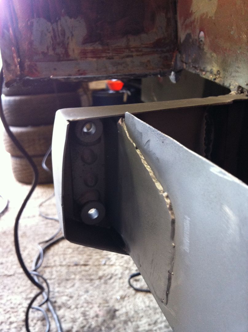
These are only £5.40 :-)


#14 JonnyAlpha

JonnyAlpha

    Up Into Fourth

  • Members
  • PipPipPipPipPipPipPipPipPip
  • 2,744 posts
  • Location: North Devon
  • Local Club: Exmoor Minis

Posted 12 May 2014 - 06:08 PM

As part of the repair above, instead of trying to repair my rear arches (Far too many holes and bad previous repairs) I have just received a LH and RH Wheel Arch Repair panel these


With regards to fitting these and the other repair pieces can anyone clarify how they should be welded? i.e. Plug or Seam Welded?


I have a couple of links to replacing sills and floor pans but what about the Rear Arch repairs and the heel board repair pieces, in the pics above the heelboard pieces have been plug welded?


My guess is that the wheel arch repair panels are also plug welded to the arch on the rear quarter and plug welded to the inner side rear shock mount section.


Front floor pan - plug welded where it overlaps the front toe board and inner side but what about where it meets the door steps? 


For the plug welding i'll be drilling lots of holes to drill 6 to 8mm 25mm - 40mm apart (According to this)?


Thanks


#15 sonikk4

sonikk4

    Twisted Paint Polisher!!!

  • Admin
  • PipPipPipPipPipPipPipPipPipPipPip
  • 15,885 posts
  • Name: Neil
  • Location: Oxfordshire

Posted 12 May 2014 - 06:19 PM

I remove the complete wheel arch assembly then split it on the worktop, like this

IMG_1043.jpg

then plug welded the two sections together

IMG_1051.jpg

 then plug welded back in place.

IMG_1053.jpg


the one thing you should do before you remove the arch assembly is drill a couple of hone in the inner section through into the boot floor. This way it will help to align the assembly when you refit it in place.


I have this job to do again on Wills Mini Special, done the r/h side got the l/h to do

IMG_2230_zps0cade701.jpg

IMG_2239_zpsc390d937.jpg


0 user(s) are reading this topic

0 members, 0 guests, 0 anonymous users