Don't know if this helps but I have found some values in the Rover workshop manual for the TPS voltage:
Throttle closed: 0 to 1v
Throttle open 90 degrees: 4 to 5v
Throttle open 65 degrees: 3 to 4v
Stage One Kit Fitted

Posted 15 July 2014 - 09:34 PM
Don't know if this helps but I have found some values in the Rover workshop manual for the TPS voltage:
Throttle closed: 0 to 1v
Throttle open 90 degrees: 4 to 5v
Throttle open 65 degrees: 3 to 4v
Stage One Kit Fitted
Posted 15 July 2014 - 09:52 PM
Thanks guys for the advice thus far.
So I have traced the iat all the way back. The pink black wire leads to a 5 way soldered connection. All 5 are pink/black, 1 leads to the ecu, one to the iat, one to the tps and one to the diagnostic socket, the 5th I am not sure.
Measuring the voltage of these wires: at the connection, at the tps, at the iat and at the diagnostic pin. All read 0.3v
There is continuity on all of the above so no breaks.
The other wire in the iat sensor, I traced back to the ecu and then checked it with the continuity setting on my multimeter, again no breaks. No voltage on this wire, I guess this is normal since the sensor must work as a resister.
Back to the tps. I think I mentioned above I had 5v at the tps. I do but not on the pink/black wire, which reads 0.3v. The third pin reads 0v.
I guess I should be getting more than 0.3v on the pink/black wire?
Allright so according to the verry poor diagram i have got, the IAT Pink & black wire you traced back is actually the earth. it goes to the 5 point solder and then to the ECU for ground. the Diagnostic plug and the TPS are on that joint because they share the same ground, and the 5th wire which you didn't know where it goes is actually the ground wire for the Coolant temp sensor.
Up Into Fourth
Posted 15 July 2014 - 10:02 PM

Up Into Fourth
Posted 15 July 2014 - 10:06 PM
Stage One Kit Fitted
Posted 15 July 2014 - 10:06 PM
Yes, it says sensor earth on the ECU side (on the diagram)
Edited by dbcool20, 15 July 2014 - 10:10 PM.
Stage One Kit Fitted
Posted 15 July 2014 - 10:10 PM
This means if the Pink/black wire is the IAT earth wire you should have a look at the other wire (green/black) and you should get 5volts. Stupid question, but you say above you tested it and got nothing, are you sure the Igniton was on? and the other lead of your voltmeter was on a good ground? because you should get a voltage
Up Into Fourth
Posted 15 July 2014 - 10:12 PM
Stage One Kit Fitted
Posted 15 July 2014 - 10:21 PM
was busy typing my last post when you had already answered. Yes like you say thinking its the earth and with all the measuring going on maybe you missed it. I would advise you to try again just to be sure and clear all the doubts. then if you still have 0v i would do a continuity check from the IAT Pin all the way to the ECU pin and if the wire is good have a good look at the pins by the Ecu and connector, maybe you have a bent pin or corroded pin.
Hope you get it sorted.
Dan
Rocket Man

Posted 15 July 2014 - 10:27 PM
I am sorry, but I am looking at another piece of information and it looks like I got it backwards. Even though the information is more Rover generic, what it indicates is that ECU pin 8 (yellow/green) is the TPS signal/wiper, ECU pin 9 (yellow/purple) is the supply and ECU pin 30 (pink/black) is the sensor return. So, what this means if the information is correct then is that the 5VDC voltage for the TPS should be on the yellow/purple wire and the pink/black should be the earth reference for all the sensors.
I apologize for the confusion.
PM me if you need additional info.
Stage One Kit Fitted
Posted 15 July 2014 - 11:25 PM
I am sorry, but I am looking at another piece of information and it looks like I got it backwards. Even though the information is more Rover generic, what it indicates is that ECU pin 8 (yellow/green) is the TPS signal/wiper, ECU pin 9 (yellow/purple) is the supply and ECU pin 30 (pink/black) is the sensor return. So, what this means if the information is correct then is that the 5VDC voltage for the TPS should be on the yellow/purple wire and the pink/black should be the earth reference for all the sensors.
I apologize for the confusion.
PM me if you need additional info.
Thanks for clearing this up for us. Just before you posted this i was re reading this thread again and was getting more and more confused about the posts you wrote previously. I even started wondering if maybe my wiring diagram was wrong or something  So at past 1am here i was so troubled by this i had to jump out of bed and go check all this for sure in my garage.
Conclusion is I can now (re)confirm that the Green/black wire of the IAT is the supply and you should deffinitely get a 5v reading out of it. The TPS supply wire is indeed the yellow purple wire and should also have 5v.
Cheers guys. now i can sleep better 
Up Into Fourth
Posted 16 July 2014 - 02:06 PM
I am sorry, but I am looking at another piece of information and it looks like I got it backwards. Even though the information is more Rover generic, what it indicates is that ECU pin 8 (yellow/green) is the TPS signal/wiper, ECU pin 9 (yellow/purple) is the supply and ECU pin 30 (pink/black) is the sensor return. So, what this means if the information is correct then is that the 5VDC voltage for the TPS should be on the yellow/purple wire and the pink/black should be the earth reference for all the sensors.
I apologize for the confusion.
PM me if you need additional info.
Up Into Fourth
Posted 16 July 2014 - 02:11 PM

Rocket Man
Posted 16 July 2014 - 03:26 PM
There is no 5VDC at the IAT like on the TPS. Based on my latest interpretation of the Rover "scrolls" the IAT function is based on the ECU supplying a voltage (probably 5VDC) and current out of pin 16 of the ECU, green/black wire, to the IAT. Then the current goes to the sensor return, pin 30 of the ECU the pink/black wire. Apparently, the ECU is measuring the current on that circuit as the resistance of the IAT varies proportionally with the temperature.
The CTS operates in the same fashion with the same common return.
One more thing that I would check is the pink/black wire has to have at some point must be 0VDC, whether the ignition switch is on or off. With the ignition off, I would check with the Ohmmeter between a vehicle earth and a connection point for the pink/black wire to be 0 Ohms.
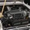
The white/blue and blue/purple wires are for the crank sensor. They are shown to have some shielding on the diagrams. I expected better than what is shown in the photo.
The grey and light green/grey wires are for the O2 sensor and they are supposed to be shielded too.
Up Into Fourth
Posted 16 July 2014 - 03:37 PM
Up Into Fourth
Posted 16 July 2014 - 03:40 PM
One more thing that I would check is the pink/black wire has to have at some point must be 0VDC, whether the ignition switch is on or off. With the ignition off, I would check with the Ohmmeter between a vehicle earth and a connection point for the pink/black wire to be 0 Ohms.


0 members, 0 guests, 0 anonymous users


