There is no current from pin16
Help Decipher These Fault Codes / Live Data Spi
Started by
minisilverbullet
, Jul 12 2014 05:21 PM
69 replies to this topic
#31

minisilverbullet
-
- TMF+ Member
-

- 3,799 posts
Up Into Fourth
- Name: Craig
- Location: Sweden
Posted 16 July 2014 - 03:42 PM
#32
xrocketengineer
-

- Members
-
- 1,637 posts
Rocket Man
- Location: Florida, USA
Posted 16 July 2014 - 03:51 PM
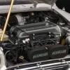
The wires you refer to are insulated! The bare braided wiring appears to be the braided wrap which covers the crank sensor/ O2 sensor plus what looks like an earth. The 2 pieces uninsulated wiring from the O2 and crank connect to the black (earth?)
Yes, the shielding is to dissipate unwanted electromagnetic fields (interference) around circuits and is connected to ground/earth. Usually it is a wire mesh covering most of the wire length.
#33
xrocketengineer
-
- Members
-
- 1,637 posts
Rocket Man
- Location: Florida, USA
Posted 16 July 2014 - 03:54 PM
One more thing that I would check is the pink/black wire has to have at some point must be 0VDC, whether the ignition switch is on or off. With the ignition off, I would check with the Ohmmeter between a vehicle earth and a connection point for the pink/black wire to be 0 Ohms.
With both ignition on and off, I get 0 ohms
So, the pink/black wire is doing what it is supposed to to do. If the ECU connection is good then maybe the ECU is acting up. You said that the temperature gauge in the car works, then the CTS circuit is at least is partially working but the ECU is not reading the current for the CTS either. Maybe the IAT sensor circuit problem overrides everything else.
Edited by xrocketengineer, 16 July 2014 - 03:59 PM.
#34
minisilverbullet
-
- TMF+ Member
-
- 3,799 posts
Up Into Fourth
- Name: Craig
- Location: Sweden
Posted 16 July 2014 - 04:28 PM
So, the pink/black wire is doing what it is supposed to to do. If the ECU connection is good then maybe the ECU is acting up. You said that the temperature gauge in the car works, then the CTS circuit is at least is partially working but the ECU is not reading the current for the CTS either. Maybe the IAT sensor circuit problem overrides everything else.One more thing that I would check is the pink/black wire has to have at some point must be 0VDC, whether the ignition switch is on or off. With the ignition off, I would check with the Ohmmeter between a vehicle earth and a connection point for the pink/black wire to be 0 Ohms.
With both ignition on and off, I get 0 ohms
Coolant sensor is working, I can see the live data on the code reader. I can see it increasing after start up.
#35
minisilverbullet
-
- TMF+ Member
-
- 3,799 posts
Up Into Fourth
- Name: Craig
- Location: Sweden
Posted 16 July 2014 - 05:16 PM
Here is an oddity
I have plugged my multi meter into the 2 sockets in the iat sensor. I also have the code reader attached to the car, so I can see live data.
When I set the multimeter to the highest ohms setting (200) I see a temp of 18. If I decrease the ohm setting to 2000 to 20k to 200k to 2000 ( I guess in essence I am refusing the residence)!the temp decreases at each decreased click of the multimeter. Pretty weird huh?
As I understand this is how the iat sensor works. As the temp increases it reduces it's resistance.as I said I had 2 sensors and one is straight out the packet.
Maybe there shouldn't be a 5v supply to the iat at all?
#36
xrocketengineer
-
- Members
-
- 1,637 posts
Rocket Man
- Location: Florida, USA
Posted 16 July 2014 - 06:11 PM
Keep in mind that the Ohmmeter has to apply a small current to an inactive circuit (ie a resistor) in order to read a resistance value. By connecting the Ohmmeter to an active circuit, like you did, it will alter the circuit function. In the case of my friend that attempted to "measure resistance" on an active 120VAC circuit that resulted in screwing up the brand new VOM.
What might be happening is that in the presumed absence of a current source at pin 16, the current from the Ohmmeter is being sensed by the ECU at pin 16 resulting in some temperature reading. The ranges of the Ohmmeter vary the amount of current needed to test a resistance circuit, so you see different temperatures.
Maybe FlyingScot or icklemini can shed some light on what should be on pin 16 voltage wise based on their experience.
#37
dbcool20
-

- Noobies
-
- 91 posts
Stage One Kit Fitted
Posted 16 July 2014 - 08:22 PM
As said again and again and again the IAT green/black wire (ie pin16) when measured with sensor removed should read 5v in normal conditions. I have checked this value personally on my own spi.
#38
minisilverbullet
-
- TMF+ Member
-
- 3,799 posts
Up Into Fourth
- Name: Craig
- Location: Sweden
Posted 16 July 2014 - 08:23 PM
That makes sense! Thanks again for the help.
Just been out to the car again, taking pictures of it to sell it on ebay. Just joking!
So connected the sykes code reader again, I have the rover 2 pod. When it is connected the options are- standard MPI or MPI sequential. I have been using the standard MPI option. I just tried the sequential option, everything is the same in terms of live data. But I have a third stored fault - Cam sensor fault.
Does the 96 spi have a cam sensor?
#39
minisilverbullet
-
- TMF+ Member
-
- 3,799 posts
Up Into Fourth
- Name: Craig
- Location: Sweden
Posted 16 July 2014 - 08:24 PM
As said again and again and again the IAT green/black wire (ie pin16) when measured with sensor removed should read 5v in normal conditions. I have checked this value personally on my own spi.
That is that confirmed then! I definitely don't have a 5v supply at the iat.
#40
xrocketengineer
-
- Members
-
- 1,637 posts
Rocket Man
- Location: Florida, USA
Posted 16 July 2014 - 08:46 PM
Well it looks like you need to get the ECU repaired. I had one done by these guys http://www.atpelectronics.co.uk/ It was not cheap but worth it. It was a spare I got from the original car seller. It was rebuilt and the immobiliser function removed. The original ECU would keep the main relay engaged all the time and would drain the battery over several days.
The performance of the car is significantly better with the new ECU.
#41
dbcool20
-
- Noobies
-
- 91 posts
Stage One Kit Fitted
Posted 16 July 2014 - 08:57 PM
To my knowledge only the MPI have the cam sensor, not the SPI. so it would be normal to get that fault if you don't have one on your car.
About the IAT again, You said your diagnostics tester indicates 35 degrees. and the value doesn't change. according to the The Rover MEMS pdf i have this is the standard fixed value the ECU will use in case of a fault. which then means your car is most certainly in limp home mode. If you don't have a feed on the green/black wire (ie pin 16) and you are 100% positive that the wiring is good and you have no damaged pins or corroded pins, then i guess like xrocketengineer said above unfortunately you might have to start thinking about the ECU.
Maybe when the ECU is in limp home mode, as it uses a standard fixed value of 35 degrees to simulate an IAT it might be normal that you don't get voltage from the pin 16. But unfortunately i do not have enough knowledge on the MEMS system and this is just a mere supposition. You could try swapping ECU if you manage to get another one around and see if it does the same, but unfortunately might be hard to get depends where you are.
#42
FlyingScot
-

- TMF Team
-
- 2,660 posts
Up Into Fourth
- Location: Inverclyde Scotland
- Local Club: Mini Cooper Register
Posted 17 July 2014 - 01:00 AM
Sorry to come late the the party...
SPi doesn't have a cam sensor.
There should be 5V supply to the IAT sensor, but this should be measured by a voltmeter between the two connections to it.
The earth is the ECU earth (pink/black).
Minisilverbullet you are lucky not to wreck your multimeter putting it across the sensor connector when it's live and I would would agree with xrocketengineer that it is the current supplied by the multimeter which is altering the reading seen on the code reader.
I would use a pin to pierce the cable green black close the ECU to check for 5V in case if cable breakage in the supply to the sensor.
35 degrees is the LOS mode value substituted by the ECU in case of IAT sensor fault (or lack of signal).
MEMS ECU is pretty robust so I would be carefully checking all the wiring not only at the IAT sensor but also the supply voltages to the ECU (from memory there is more than one supply to it)
If it isn't a wiring fault then it points to the MEMS unit
FS
#43
xrocketengineer
-
- Members
-
- 1,637 posts
Rocket Man
- Location: Florida, USA
Posted 17 July 2014 - 01:29 AM
Sorry to come late the the party...
SPi doesn't have a cam sensor.
There should be 5V supply to the IAT sensor, but this should be measured by a voltmeter between the two connections to it.
The earth is the ECU earth (pink/black).
Minisilverbullet you are lucky not to wreck your multimeter putting it across the sensor connector when it's live and I would would agree with xrocketengineer that it is the current supplied by the multimeter which is altering the reading seen on the code reader.
I would use a pin to pierce the cable green black close the ECU to check for 5V in case if cable breakage in the supply to the sensor.
35 degrees is the LOS mode value substituted by the ECU in case of IAT sensor fault (or lack of signal).
MEMS ECU is pretty robust so I would be carefully checking all the wiring not only at the IAT sensor but also the supply voltages to the ECU (from memory there is more than one supply to it)
If it isn't a wiring fault then it points to the MEMS unit
FS
Glad that you could join us! I was beginning to run out of steam. I did learn a few things too. I have a question that maybe you can clarify. The Rover Mini wiring diagram shows the ECU pin 29 to be power from the relay and 28 earth. The "Chapter 14 " publication shows the two reversed even though everything else pretty much lines up. Is one of the two publications wrong?
#44
FlyingScot
-
- TMF Team
-
- 2,660 posts
Up Into Fourth
- Location: Inverclyde Scotland
- Local Club: Mini Cooper Register
Posted 17 July 2014 - 11:10 AM
Unfortunately I am your side of the "pond" this week xrocketengineer so my treasured notes and manuals are not to hand....
I will check on my return to see what I have.
Damn work stops play as usual
FS
I will check on my return to see what I have.
Damn work stops play as usual
FS
#45
minisilverbullet
-
- TMF+ Member
-
- 3,799 posts
Up Into Fourth
- Name: Craig
- Location: Sweden
Posted 17 July 2014 - 11:33 AM
Minisilverbullet you are lucky not to wreck your multimeter putting it across the sensor connector when it's live and I would would agree with xrocketengineer that it is the current supplied by the multimeter which is altering the reading seen on the code reader.
I guess the saying "a little knowledge is dangerous" applies here.


0 user(s) are reading this topic
0 members, 0 guests, 0 anonymous users


