Jump to content


Photo
- - - - -

Ac Dodd Fast Road Engine Build


  • Please log in to reply
43 replies to this topic

#1 djdanmk

djdanmk

    Stage One Kit Fitted

  • Noobies
  • PipPipPip
  • 81 posts
  • Location: milton keynes

Posted 06 October 2014 - 08:46 PM

Thought it was about time I started to write up my engine build project after having my first full day of engine club.


The build will be a slow one over a year or more but will post the updates as they happen to the build and final spec. The build will be in AC's engine club with him showing me how its done and learning how to do everything the right way.


If anyone has any questions then feel free to ask them and if im not sure of the answer I can ask AC.


Only just getting started but the initial spec is as follows (will be up-dated as the build progresses):


Rebuilt gearbox - Centre oil pick up pipe

                          - Full rebuild kit

                          - Mini spares X-pin diff

                          - New genuine baulk rings

                          - 3.44:1 Crown wheel and pinion with economy primary gear with standard input gear giving a final drive ratio of 3.32:1


Re-bore offset +060 taking it to 1330 with Omega pistons with 6.5cc offset dish


AC Dodd - RS+ cross drilled steel billet cam


Piper cams lightweight vernier duplex kit


New pre verto clutch with orange diaphragm and lightened steel flywheel


Rebuilt starter motor - with new bearings, brushes, fully cleaned & re-painted


Rebuilt alternator - with new rectifier, regulator, bearings, fully cleaned & repainted


Modified head - all work carried out by AC Dodd

                        - ported and polished

                        - race 29.5mm exhaust valves

                        - race 35.7mm inlet valves

                        - race bronze valve guides

                        - 160lb double valve springs

                        - drilled for 11 studs

                        - 24cc chambers


New rocker assembly - probably forged 1.3


Twin HS4 carbs fully rebuilt with itg air filter and MED stub stacks


Maniflow LCB and single back box centre exit exhaust


Edited by djdanmk, 26 September 2016 - 10:56 PM.


#2 Ben_O

Ben_O

    Mill Road Garage

  • Paint Doctor
  • PipPipPipPipPipPipPipPipPipPip
  • 9,781 posts
  • Location: Isle of Wight

Posted 06 October 2014 - 10:44 PM

Good luck!


#3 djdanmk

djdanmk

    Stage One Kit Fitted

  • Noobies
  • PipPipPip
  • 81 posts
  • Location: milton keynes

Posted 07 October 2014 - 07:52 PM

So started off by rebuilding the starter motor. First job was to test it using a battery, jump leads and a large screwdriver. The motor run ok and sounded fine, but then it was onto stripping it down into parts ready for inspection.


All stripped down ready for inspection and cleaning

20141004_111339.jpg


Once stripped down the commutator was measured for wear and then using a multi meter the armature assembly was checked to ensure none of the sectors were grounding down to the main shaft. Although the commutator was worn and at the lower end of the recommended limit all it needed was a machine by AC on the lathe to bring it up like new. 


All cleaned and machined ready to be rebuilt

20141004_145519.jpg


Once all the parts were fully cleaned with all old paint and dirt removed the steel parts received a coat of red oxide primer and then a coat of satin black or gold. The end housing was given a coat of acid etch and then sprayed silver.


The only parts that were worn were the bearings and the brushes so these were both replaced and the motor re-assembled.


All shiny and like new but old

20141004_172655.jpg


All that's left to do is test it once I borrow a set of jump leads or when im next at AC's.


#4 ACDodd

ACDodd

    Up Into Fourth

  • Mini Docs
  • PipPipPipPipPipPipPipPipPip
  • 2,654 posts

Posted 09 October 2014 - 04:55 PM

Loving the build blog, excellent!!
 
Those who do engine club do it properly!
 
AC

Edited by ACDodd, 09 October 2014 - 07:12 PM.


#5 djdanmk

djdanmk

    Stage One Kit Fitted

  • Noobies
  • PipPipPip
  • 81 posts
  • Location: milton keynes

Posted 01 January 2015 - 12:01 AM

Well thought it was about time for an update.


With the starter motor finished it was time to test it using a fully charged battery, set of jump leads and large screwdriver. By clamping the starter motor in the vice, attaching the negative from the battery to the body of the motor and the positive to the starter solenoid being careful at all times no not short out the battery. The screwdriver was then used to complete the circuit and test the operation of the motor.


Startermotortesting.jpg


With the starter motor done it was time to move onto testing and rebuilding the alternator. As well as my alternator I also rebuilt one for AC. First we bolted my alternator into the vice and hooked it up to AC's alternator testing rig. Using a drill with socket attached to spin up the alternator we ran the alternator and put load onto it and checked that it was producing the correct voltages. All was well so we moved onto testing the second one. This was another story though and was not charging.


On dismantling the alternators the fault with the one which was not charging was discovered to be a stuck brush that had worn down in use and so was no longer in contact with the slip ring. The slip rings were also very worn and required changing. The first alternator although working fine was very close to developing the same fault as the brushes were very close to becoming stuck.


20141025_115425.jpg


With both alternators fully dismantled it was time to clean all of the parts ready for rebuilding and painting. Before painting the end housing three holes were drilled and taped to allow screws and washers to be installed to hold the new bearing in place. One of the housings was also cracked where one of the bolts that holds the alternator together runs through, so this was welded to repair it.


20141025_154203.jpg


The housings were then etch primed and painted in silver. All steel parts were red oxide primed and painted in satin black. Unfortunately on my next visit to engine club the alloy parts had a reaction in the paint, so these were stripped back to bare metal and repainted. The new bearings were then pressed in and the alternators rebuilt with new parts as required.


As I run out of time to test them on my last visit AC tested them both and reported that they are all working as expected.


The next stage for the rebuild will be the gearbox. Over the Christmas hols I have finally had the time to finish stripping the engine down to get the gearbox off ready and make it much easier to move around on my own.


20141011_145243.jpg


20141130_144608.jpg


20141130_145911.jpg


20141130_150128.jpg


20141229_154328.jpg


20141229_161633.jpg


20141229_161642.jpg


#6 djdanmk

djdanmk

    Stage One Kit Fitted

  • Noobies
  • PipPipPip
  • 81 posts
  • Location: milton keynes

Posted 20 January 2015 - 11:04 PM

So the first engine club of the new year and the time has come to re-build the gear box.


The first decision was which final drive the gearbox would have. As I live in Milton Keynes and have a lot of 60 & 70 MPH speed limits on the roads the decision was to go for a 3.44:1 crown wheel and pinion as opposed to the 3.1:1 already installed and change the primary gear to an economy one. This means the engine will have a drop gear ratio of 0.9666:1 giving a final drive ratio of 3.32:1. This will give a good balance of acceleration/cruising RPM, at 70MPH the car should be doing around 3900RPM.


20150117_113834.jpg

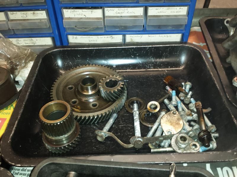
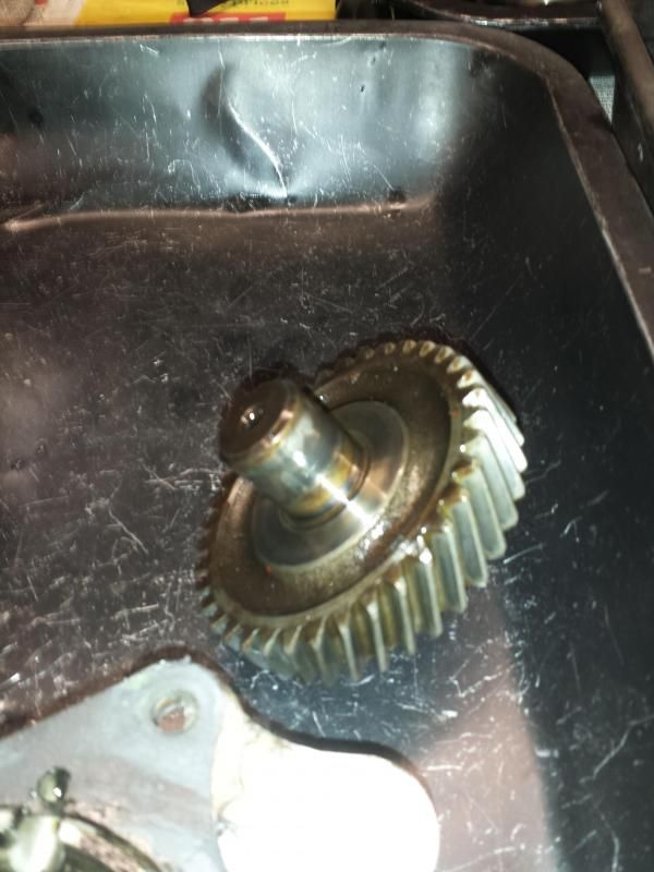
New crown wheel and pinion and primary gear.


First up was to remove the diff side plates followed by the diff case and diff. As I will be installing a new X-pin diff the existing unit was not inspected for wear. During the strip down three trays were used for the components, one for the casings/diff, one for gears/bolts/ect and one for all worn parts. The diff side plates were checked for play using a pot joint. One side was ok but the other had too much play and will be replaced. Next up the speedo drive and housing were removed and the gearbox placed on its end to allow the remaining oil to drain out (while I put the kettle on).


20150117_113820.jpg


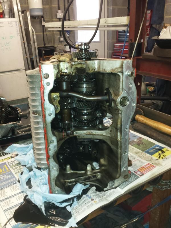
In the above picture the idler gear has also been removed. This was inspected and has worn on both shafts so will have to be replaced (see picture below). 


20150117_113852.jpg


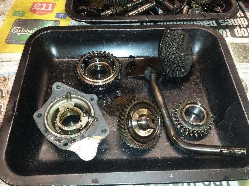
Next up was to remove the oil pick up pipe, this wont be getting re-used as a central oil pick up will be fitted. With this out the way the gear box was locked in first and fourth gear by pushing the 1st/2nd synchro hub to the left and 3rd/4th synchro hub to the right (first disengaging the gear selector). With this done the input gear circlip was removed followed by the bearing rollers and cage. The bearing centre could then be prised off using two tyre leavers. Each roller was inspected for wear and then reassembled. Next up the lock tabs were knocked back and the input gear removed followed my the main shaft nut and bearing retainer plate. With this done the layshaft could be pushed out allowing the gears to be rolled up and out of the box. The reverse gear could then also be removed along with the oil strainer. Using the tyre leavers again the input gear was removed from the third motion shaft. The two main bearings was then drifted out which allowed the main gears to be removed (making sure to hole both ends of the gears on the shaft as they are removed to avoid parts of the syncro hubs ending up all over the place).


This just left the gear selector roll pin to be drifted out and the shaft and forks to be removed (being carful not to let the forks slide too far to the left and bend the shaft). After this the rest of the selector mechanism was removed.


The last part to remove from the box was the idler gear. The case was heated around the bearing using a propane torch and the bearing was then knocked out using a socket.


20150117_162422.jpg

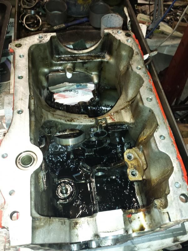
Empty case ready for cleaning


20150117_162401.jpg

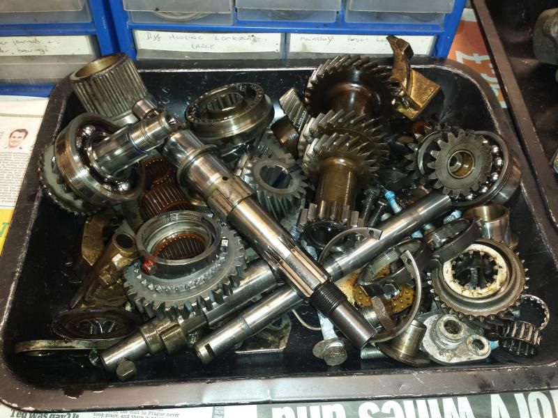
Gearbox components ready for cleaning


20150117_162414.jpg

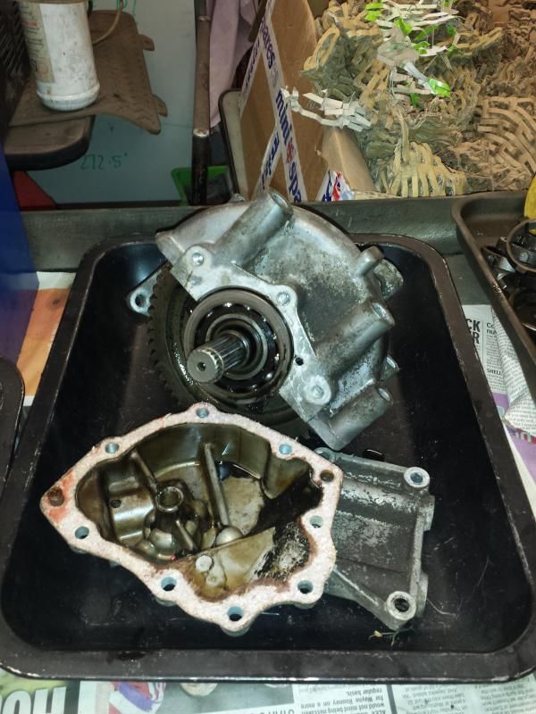
Casings and old diff


With everything apart it was time to clean down all the tools and inspect the parts for wear. The gearbox case was all fine with all threads intact (more checks will be done once all clean). It was then onto removing the gears from the third motion shaft. Upon removing the gears the second gear idler and 1st/2nd syncro hub both had too much wear and will have to be replaced.


20150117_162353.jpg

Tray of attrition


So at this time for the rebuild I will be using the following parts:


- A+ gearbox rebuild kit less diff parts

- 1st/2nd syncro hub (2nd hand)

- 2nd gear idler  (2nd hand)

- Diff side plate

- Centre oil pick up pipe

- Idler gear (2nd hand)

- Mini Spares X-pin diff

- Diff bearings

- Syncro springs

- 2nd hand 3.44:1 crown wheel and pinion

- Diff crown wheel bush

- 2nd hand economy primary gear

- Primary gear front and rear bushes

- New genuine baulk rings


#7 djdanmk

djdanmk

    Stage One Kit Fitted

  • Noobies
  • PipPipPip
  • 81 posts
  • Location: milton keynes

Posted 10 December 2015 - 11:53 AM

Right thought it was about time I did an update as its been a while. So with everything stripped down all the new parts were ordered and this lot arrived:


20150127_222817_1.jpg


With all the new parts it was time to get down to cleaning the case and diff/speedo covers. First all the threads were cleaned out using a tap and any paint/ stubborn dirt was scrapped off and then all the alloy parts were put on a hot wash cycle in the dishwasher. After a lot more scrubbing with hot water and degreaser using wire brushes/scouring pads all of the parts were clean and ready for painting:


20150318_192504.jpg


Once clean and dry they were given one final clean with brake cleaner and then masked up ready for painting with etch primmer and then alloy wheel silver:


20150327_170730.jpg

20150327_170753.jpg


With everything clean and painted it was time to get on with the rebuild. First the 1st/2nd and 3rd/4th gear syncros were given a final clean and put back together using new springs and plenty of engine oil between all the components. Before fitting the springs squeeze all of them between two fingers and match the ones that feel the same in the same syncro. When doing this it takes some patience to make sure the two parts go back together with the balls locating into the right part. Lucky they both went back together the first time with out losing any balls, however when checking the operation of them I did push one of the inners out too far allowing some of the springs and balls to break for freedom resulting of a search around the floor for them.


20150314_150707.jpg


With them out the way it was time to rebuild the main shaft. Before starting all of the bulk rings were tested for the best fit on each of the gears. In the end 2 genuine bulk rings and 2 non genuine mini spares bulk rings were used as 2 of the genuine ones had a very bad fit. Each gear was placed on the shaft in turn using plenty of oil between each part. If taking the 4th and 3rd gear retainers out was a pain getting them back in was just as bad.


20150314_164643.jpg

20150314_164657.jpg

20150314_171231.jpg


Once the new idler bearing had been fitted by heating the casing and drifting the new bearing in. The next part of the box to go back together was the shifter mechanism. This was given AC's slick shift modification. Both forks were then tested on the syncros for the correct fit. The 1st/2nd fork was a little loose so with some slight modification in the vice and with pliers it was adjusted until it was as good as new. Then all the parts were put back into the box:


20150404_112304.jpg

20150404_120327.jpg


With all that done the main shaft could then be put pack into the box:


20150404_141855.jpg


Then the bearings installed to hold the main shaft in its final position along with the first motion shaft and reverse gear. The new central oil pick up pipe was then inspected to ensure the gauze was fitted correctly and then cleaned out with a good load of break cleaner and air. It could then be trial fitted to the box to ensure it lined up and then removed before putting the lay shaft back into place with the existing thrust washers:


20150404_150755.jpg


The end float was then checked using feeler gauges and found to be 0.008 which was over the maximum of 0.006 allowed. After swapping the thrust washer for a different one this brought the end float down to 0.0025 which was much better. The bearing retainer was then measured and shimmed and put back in with the lay shaft/reverse idler lock place and bolting in place and the lock tabs bent back over.


20150404_154806.jpg


With all that done the central oil pick up pipe was installed (the reason for upgrading to a central oil pick up was to prevent oil starvation during long right hand bends as the standard pick up is on the right hand side looking towards the front of the car) along with the pinion/lock tab and nut and the input gear with its lock tab and nut. The box was then locked in 1st and 4th and both nuts torqued to 150 lb ft. It was then taken out of 1st and 4th and everything rotated to ensure it operated correctly.


To be continued...


Edited by djdanmk, 26 September 2016 - 03:06 PM.


#8 djdanmk

djdanmk

    Stage One Kit Fitted

  • Noobies
  • PipPipPip
  • 81 posts
  • Location: milton keynes

Posted 14 December 2015 - 04:18 PM

With all the gears back in the case it was time to put the speedo drive back into place. For my final drive set up a 6 tooth speedo worm gear was needed with the 17 tooth pinion.


20150523_111435.jpg


All the bolts and parts were cleaned and then the speedo cover and gears installed using RTV sealant on both sides of all gaskets to ensure no leaks. With that all done it was time to move onto the diff. The old diff was dissembled to remove the crown wheel bolts, lock tabs and output shafts. When dissembling the old diff it is important to drill out enough clearance to get a drift in to remove the roll pin or like me you will end up getting the drift stuck in the diff cage. All parts were cleaned along with the new 3.44 crown wheel.


20150523_142941.jpg


With all the parts ready it was time to start building the new mini spares cross pin diff. A cross pin diff to chosen to handle the extra power that the engine will have. First all parts were laid out ready in a clean tray:


20150523_143544.jpg


The retaining grub screw was then removed and the diff disassembled to allow the output shafts and planet gears to be installed. As I took the pins and centre block out I laid them in the tray in the same order as they came out so that on reassembly I could ensure all the parts went into the correct place. Here is the diff all built up:


20150523_151846.jpg


The crown wheel along with the other output shaft was then installed and the bolts torqued up and the lock tabs bent over. The box was then placed on its side and the diff housing was installed along with the diff and one side cover with gasket to allow the diff to be measured to work out the correct amount of shims to preload the diff. With the number of shims worked out the casings were taken off and the cover installed with RTV sealant, my box did not have gaskets fitted for this cover so none were used during the rebuild just the sealant. the  gear selector ball bearing and spring were then installed with a new o-ring and the right hand cover installed using RTV on both sides of the gasket. Onto the left side the shims were installed along with the gasket and cover. All the bolts were then checked to ensure they were tight enough and the lock tabs bent over.


20150613_120818.jpg

20150613_120826.jpg

20150613_120830.jpg

20150613_120836.jpg


The last jobs for the gear box were to install the new gear selector seals, bush for the rod change and speedo pinion bush.


Edited by djdanmk, 26 September 2016 - 03:29 PM.


#9 littlewimp

littlewimp

    Mini Mad

  • Noobies
  • PipPipPipPip
  • 104 posts
  • Location: forest of dean. gloucestershire

Posted 14 December 2015 - 06:38 PM

Some very nice work being done there, looking better than new.


#10 Rocket.

Rocket.

    One Carb Or Two?

  • Members
  • PipPipPipPipPipPipPip
  • 1,441 posts
  • Location: UK

Posted 14 December 2015 - 06:46 PM

Nice build !


Great Source of information


#11 djdanmk

djdanmk

    Stage One Kit Fitted

  • Noobies
  • PipPipPip
  • 81 posts
  • Location: milton keynes

Posted 15 December 2015 - 10:16 PM

Thanks for the comments cleaning the gearbox case is a right pain with all the little nooks you need to scrub to get all the old oil and crap off but it is worth it and necessary in the end to get a good looking and functioning part that will last.


While I was in the finishing stages of the gear box and deciding on the next part to get onto I decided that I would have AC do all of the work to the head so in between engine clubs I dropped it down to him and got back the finished head below (you can see the full spec of the head at the start of this build), If you are friends with AC on Facebook them I'm sure you would of seen progress pictures of it as the work progressed:


20151215_210158_1.jpg

20151215_210217.jpg

20151215_210256.jpg

20151215_210305_4.jpg

20151215_210355_3.jpg


#12 littlewimp

littlewimp

    Mini Mad

  • Noobies
  • PipPipPipPip
  • 104 posts
  • Location: forest of dean. gloucestershire

Posted 15 December 2015 - 10:24 PM

That Head looks a bit special, how much did that cost you if you don't mind me asking ?


#13 djdanmk

djdanmk

    Stage One Kit Fitted

  • Noobies
  • PipPipPip
  • 81 posts
  • Location: milton keynes

Posted 16 December 2015 - 08:46 AM

All of the parts were £245.71 with my minispares discount, the valve guides were from AC. I will have to dig out the receipt for all of the work as I can't remember the price now. I am very pleased with it I would recommend anyone have a talk with AC for any engine bits.

#14 José Cardoso

José Cardoso

    Just On Tickover

  • Noobies
  • Pip
  • 6 posts
  • Location: Porto

Posted 18 December 2015 - 12:52 AM

Great engine rebuilding :)


You have convert your engine head to run with the water pump by-pass.


What was the reason, it is better to maintain the low/good temperature?


Cheers!


#15 djdanmk

djdanmk

    Stage One Kit Fitted

  • Noobies
  • PipPipPip
  • 81 posts
  • Location: milton keynes

Posted 19 December 2015 - 10:43 PM

The head that came with the engine I brought for rebuilding already had a bypass so I kept it. I will be using a good quality silicone bypass hose to avoid the usual problem with cheep hoses leaking.


1 user(s) are reading this topic

0 members, 1 guests, 0 anonymous users