Jump to content


Photo
- - - - -

Ac Dodd Fast Road Engine Build


  • Please log in to reply
43 replies to this topic

#16 djdanmk

djdanmk

    Stage One Kit Fitted

  • Noobies
  • PipPipPip
  • 81 posts
  • Location: milton keynes

Posted 19 December 2015 - 11:23 PM

So with the gear box finished and the head sorted out I decided to rebuild the carbs next. I brought a set of twin HS4 carbs before I got the engine so these were first stripped down and every part given a very good clean. I don't have any pictures of them before they were taken apart but they were very dirty and the dashpots had been painted in lacquer which had gone very yellow.


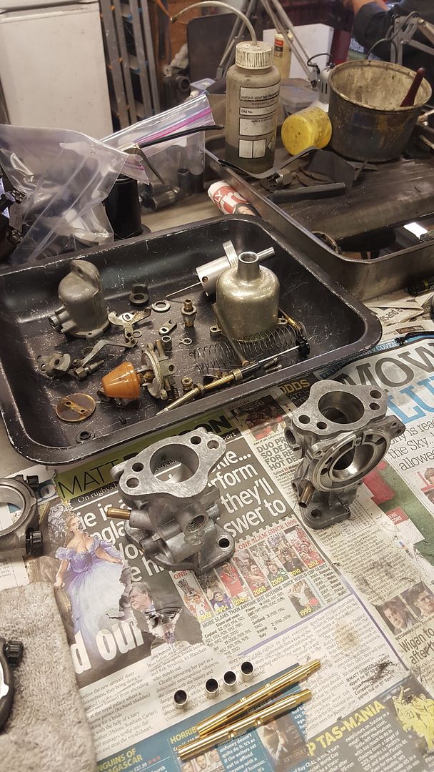
So the carbs were stripped down and all parts cleaned:


20150613_151700.jpg


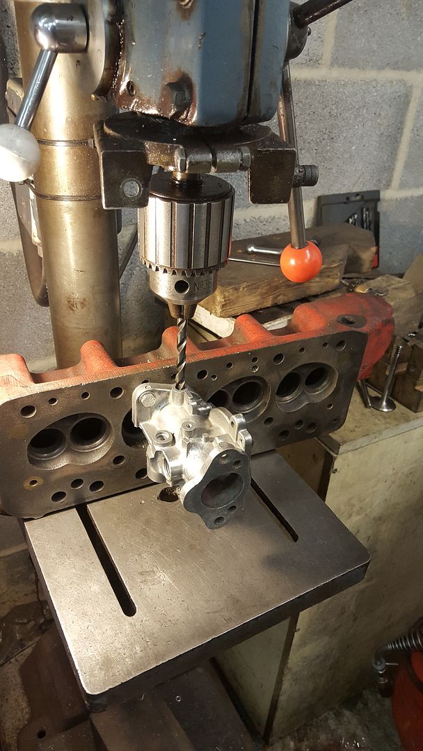
With both bodies cleaned it was time to replace the worn bushes. One at a time the carbs were mounted onto AC's pillar drill using an old cylinder head that he uses to hold the carb body square while drilling. The carb is bolted onto the head and the head bolted down. To ensure that the new bushes will be square in the body a drill bit is fitted to the drill to allow the position of the body to be adjusted until you can bring the drill bit down through the body, let go and the drill will retract the bit on its own without snagging. With this done the old bushes can be drilled out using a 9.2mm drill bit:


20150613_153745.jpg


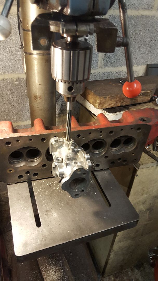
Once this is done the holes can be line reamed to 9.5mm ready for the new bushes:


20150613_154624.jpg


The two faces of the carbs were then linished to ensure they were fully clean and flat and any burrs round the edges cleaned with a needle file. The carb bodes were then cleaned using brake cleaner and the carb bodies mounted in the vice to allow the new bushes to be drifted into place. When installing the bushes they need to be inserted until they just touch the inside of the body where the throttle butterfly will fit to avoid air leaks. Now the carbs have had new bushes fitted in the future if I ever need to replace them then I can just remove the old ones and insert new ones. The throttle butterfly's and shafts were then inserted and the retaining screws fitted loosely. Ensuring the throttle disks are the right way round you then hold it closed with a finger and hold the carb up to a good light source. You can then adjust the position of the shaft and disk slightly to get the best possible fit before tightening the screws and bending the back of the screws out to ensure they stay in place. At each stage of rebuilding every part should be well oiled using engine oil to ensure smooth operation.


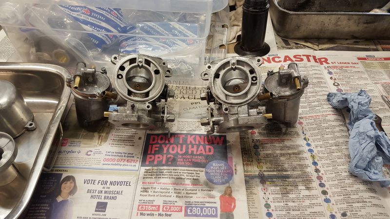
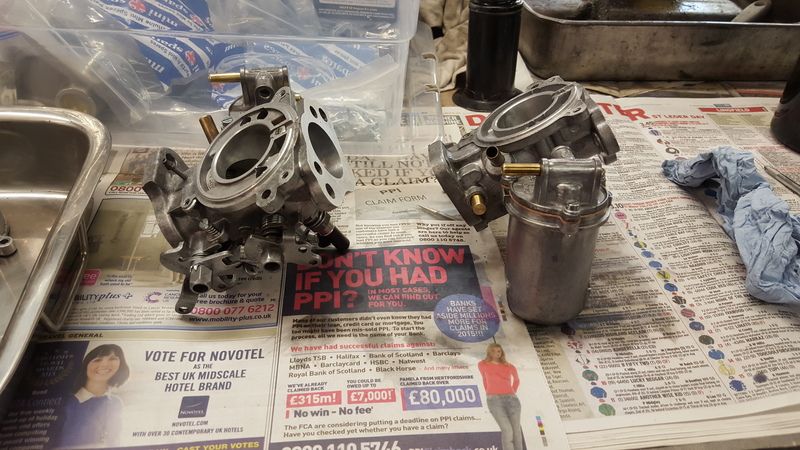
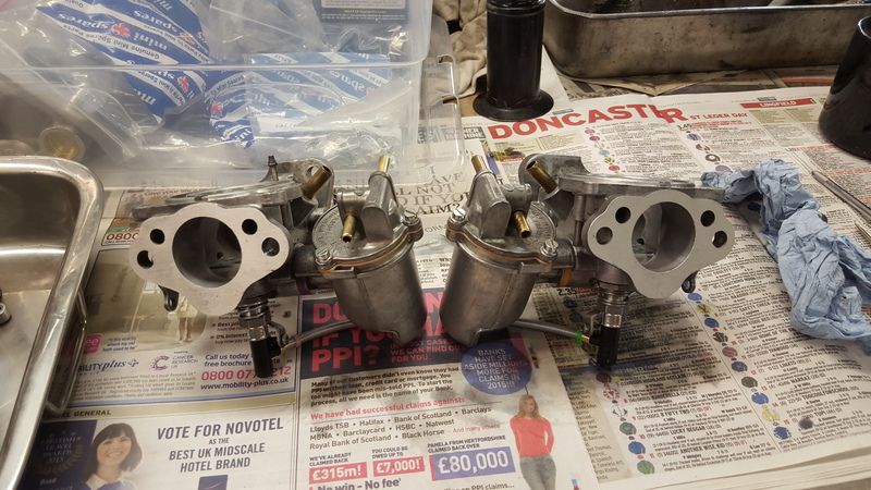
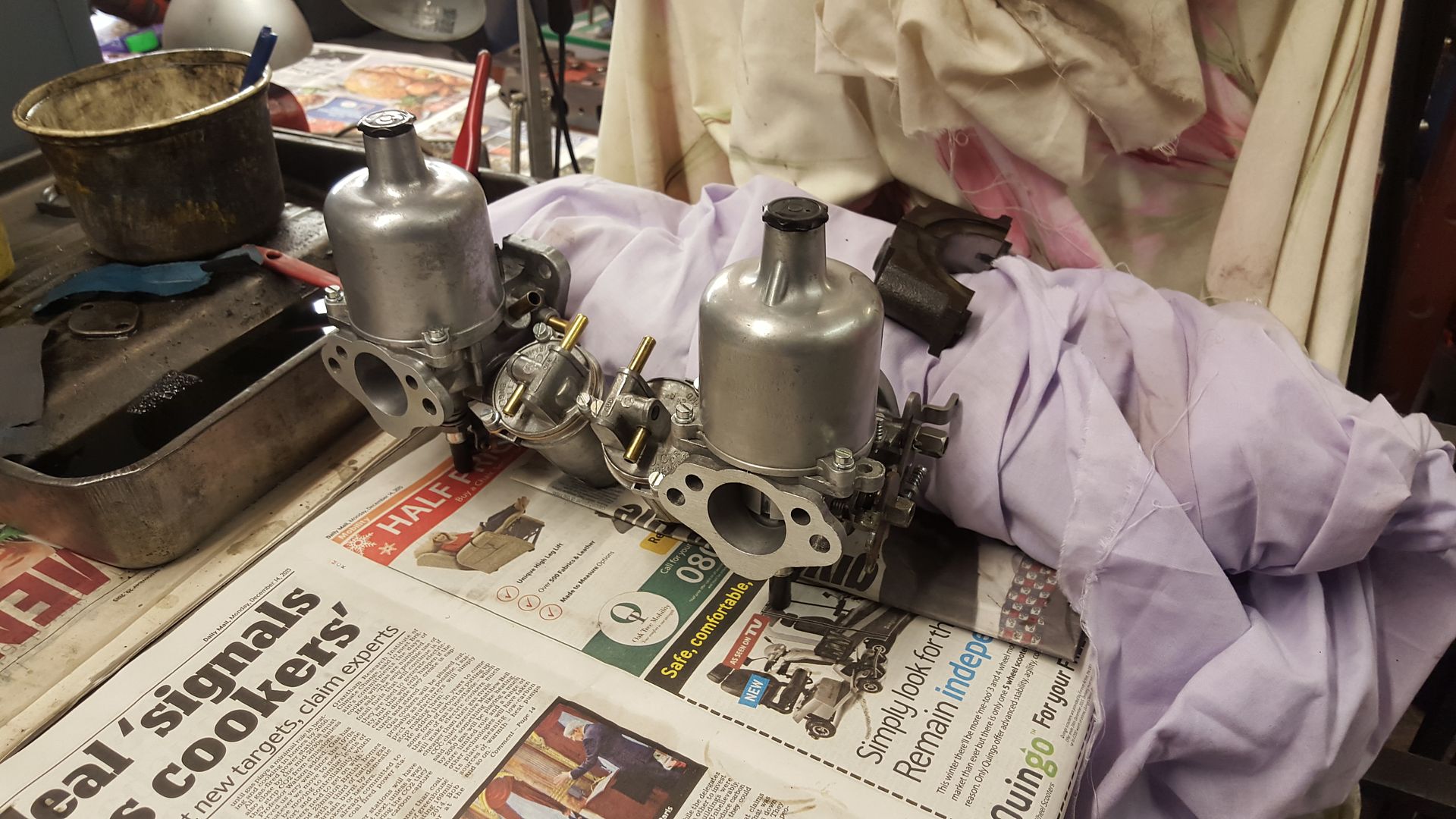
With this done the rest of the carbs could be rebuilt. It was very useful having AC on hand while doing this as the instructions that come with the rebuild kit are useless. If you are doing this at home then I would take plenty of pictures as you take them apart so you can see how all the springs and bits fit together. So after all that I ended up with two carbs that look like this:


20151003_160729.jpg

20151003_160741.jpg

20151003_160756.jpg


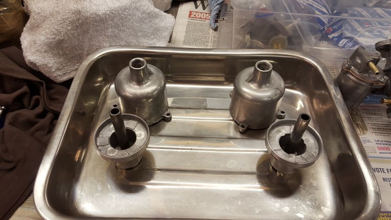
The last part I had time for at this engine club was to balance the dash pot pistons this is essential to ensure the carbs work as a pair, if this is not done then the dash pots will respond differently and be very hard to tune and get good results from. Fist they were given a good final clean and checked to ensure that they fitted together smoothly.  


20151003_160732.jpg


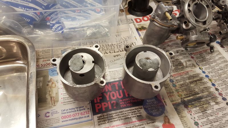
The holes in the pistons were then blocked up using blue tack and lightly oiled using a light oil and then put together. You then hold each piston at the top of the dash pot and let them go at the same time and watch how they fall. You need to do this a few times to see if they fall at the same time. Mine most of the time fell together so did not need any further work so the new AAU swinging needles were fitted and the dash pot assembly's fitted to the carbs.


20151003_163249.jpg


The last job was to set the idle screws, these were screwed down until they met the throttle lever and then turned 2 1/2 turns. I forgot to add earlier in the post the jets were also set at this stage to give an initial setting when they are fitted to the engine. I had brought all new screws for the dashpots/float chambers and idle screws as the old ones were quite churned up and miss matched I how ever forgot to get new fast idle screws, as I had run out of time at this engine club the carbs will be mounted onto the manifold and fully finished at the next one. I will be running the engine in on a HIF44 carb and then these fitted will be fitted after.



#17 ACDodd

ACDodd

    Up Into Fourth

  • Mini Docs
  • PipPipPipPipPipPipPipPipPip
  • 2,654 posts

Posted 19 December 2015 - 11:58 PM

Nice Update Dan.


AC


#18 djdanmk

djdanmk

    Stage One Kit Fitted

  • Noobies
  • PipPipPip
  • 81 posts
  • Location: milton keynes

Posted 24 December 2015 - 12:06 AM

So Sunday was the last mini club of 2015 so I took my carbs and engine block down with me. The plan before was to finish off the carbs and then move onto stripping down the block but we decided it was better to get the block stripped down and leave finishing off the carbs to another time. I'm still deciding whether to leave the dashpots with their standard finish or polish them up.


AC cast his expert eye over the block first and we discovered that someone had defiantly been inside the engine before as it had a different camshaft fitted but at this point we could not tell which one. I was told all the engine had done to it before I brought it was new gaskets all round and the head and pistons decoked.


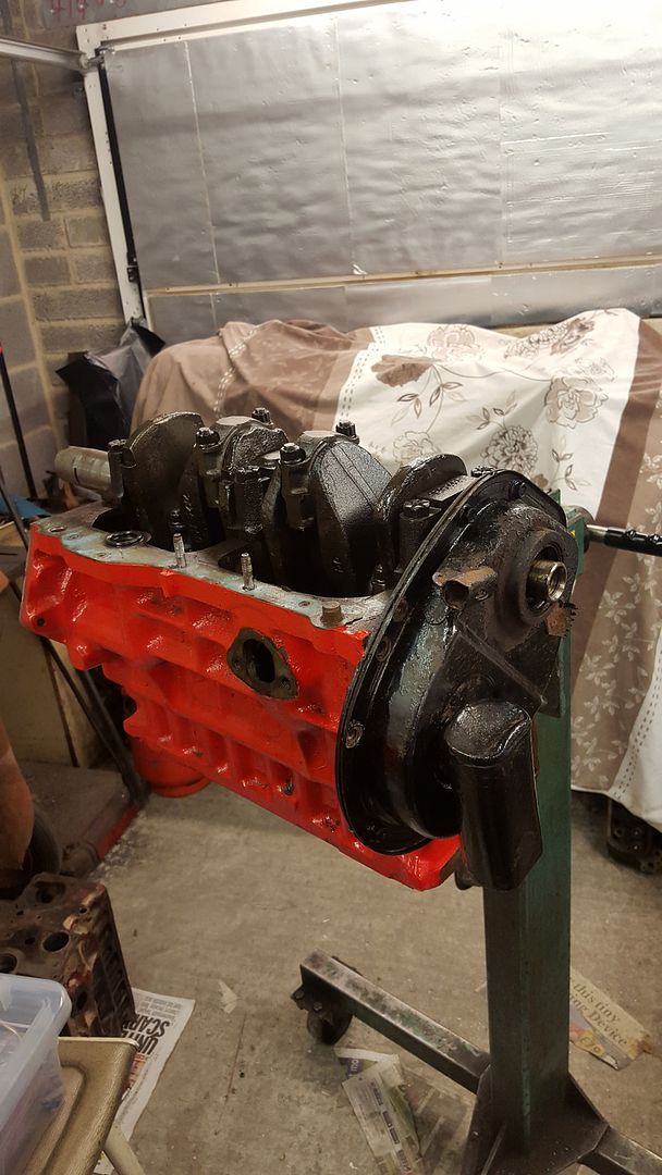
The block was mounted onto the engine stand to allow to be stripped down easily and first the crank damper was removed, this needed a bit of persuasion with a hammer and punch as it was a tight fit on the crank. Once it was removed there was a slight amount of galling on the crank but nothing too bad.


  20151220_111030.jpg


Next a dial gauge was set up on the end of the crank and the crank moved back and fourth to check how much wear the engine had. The crank had 5 thou of end float so although higher than factory spec of 3 thou it was not too bad.


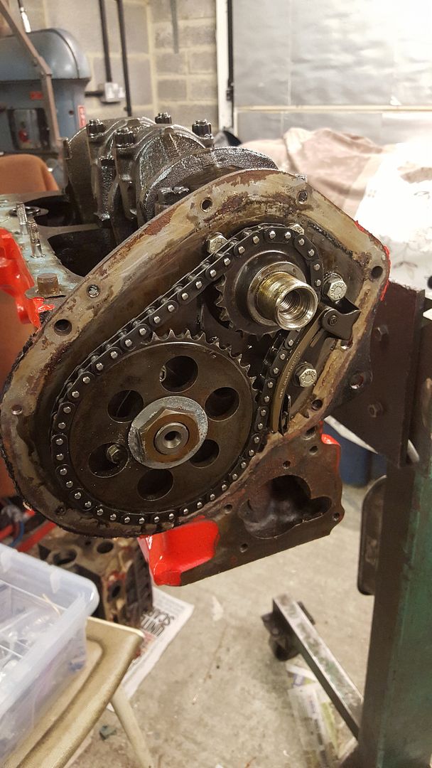
Next the timing cover was removed, this revealed that although the cam had been changed the engine was still fitted with its original timing chain.


20151220_111620.jpg


The chain tensioner was then removed and then the cam gears and chain were removed followed by the cam retaining plate, at this point it is important to be careful to stop the cam falling out if you move the engine. Before them camshaft was removed the oil pump was taken off. Once off the pump was clamped in the vice and using a large screwdriver with spanner attached the oil pump cover plate was removed. With the cover removed you can see how much wear the pump gets from the unfiltered oil and why you should always fit a new oil pump when rebuilding an engine. The wear in the pump was nothing more than expected.  


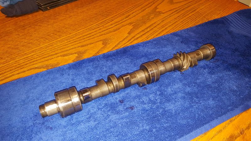
The camshaft was then removed from the engine by putting one hand on the timing gear end and rotating it while sliding it and using your other hand on the other end to feed it out slowly to prevent it from falling inside the block as it is removed to prevent damage. With the camshaft removed it was discovered that it was a Kent 286:


20151220_221900.jpg


As I will be fitting one of AC's camshafts this one went on ebay once I got home. Looking at the camshaft it was clear that it had been used in an engine but looking at the state of the cam followers in the engine and how worn they were it was clear that it had not run in this engine or the lobes would have been very chewed up. Next the block was turned round in the stand to allow the followers to fall out, any that did not fall out were given a little help with a long screwdriver.


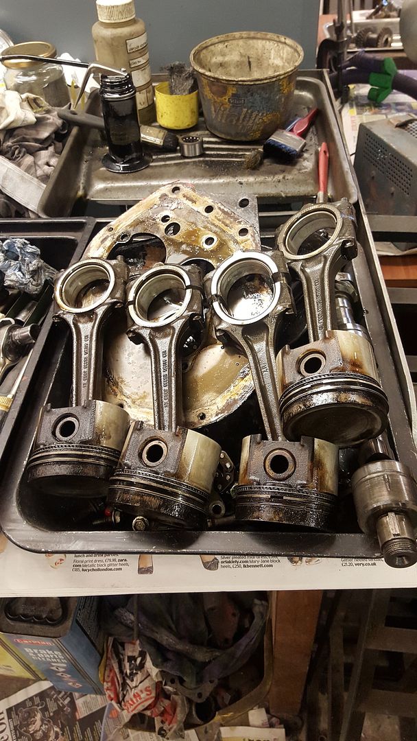
Next one by one the pistons were removed from the crank. First both nuts on the cap were loosened and undone till they were at the top of the bolt. A small copper hammer was then used to tap the nut to start the piston moving. Once the cap was removed the piston was slid out slowly ensuring that the bolts did not touch the crank and the rod did not touch the bores as it came out to prevent damage. The cap was then put back onto the piston ensuring it was put back on the same way it came off. With all four pistons removed the big ends could be inspected alone with the bearings. There was no major damage visible at this point. The pistons were also inspected, they all had quite even witness marks on them and a slight bit of galling to one but nothing too bad. The pistons were also checked for wear by putting a 0.004 feeler gauge in with the top ring. The fit was a little on the loose side so the pistons were removed from the rods and put in the scrap bin as they were not worth keeping.


20151220_115329.jpg

20151220_115334.jpg


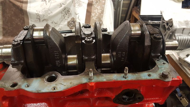
Next the thrust bearings were removed followed by the front and back caps were removed followed by the centre cap. As each one was removed it was inspected and the bearings removed. As you take the caps off you need to ensure they do not just lift straight off or some further investigation is needed. All of mine needed a bit of a force to remove. The crank was then rotated and lifted at the same time to remove it from the block. When you remove the bearings they are inspected to see if they have the standard part number on or any other markings such as +10. All of the ones fitted were to the standard size.


20151220_124835.jpg


The crank was then measured by AC. The crank will need the mains polished and the big ends ground to 10 thou undersized from standard. There was also some wear to the crank tail so this will be cleaned up when the crank is reground along with some wear to the part that the primary gear runs on. The other check to do on the crank is to check for any cracks. To do this you this you hold the crank on one web using 3 fingers 90 degrees to your hand ensuring that no washers are left on the crank and that it hangs freely. The web at the other end of the crank is then struck using a steel hammer, If the crank is good then it will ring like a bell. You are looking for a nice bright sounding ring. Every crank will have its own tone. If the crank has a crack then it will just have a dull thud to it and will not ring.


With that done all of the caps were put back onto the block ensuring they were put on with the tangs lined up and the bolts torqued down to 65 ft/lbs. When torqueing up the bolts it is important to tighten them in one motion rather than stopping and starting so that they are at the correct torque setting.


20151220_124458.jpg


Each one was then checked by AC using a dial bore gauge. The end two caps were within factory tolerance but the middle cap was not so good. The middle cap was 1 1/2 thou over the tolerance from top to bottom. This left me with the possibility of maybe having to have the engine line bored. At this point we stopped for lunch and on our return the centre cap was removed and de-greased. On closer inspection there were some witness marks from where the block had been build with some dirt in-between the cap and block. The cap was given a very light lapping to clean it up and the block was cleaned with a blunt wire brush in the drill, it was then put back on, re torqued and then re-measured. This improved things a little but not enough. So the cap came back off and was lapped again, put back on and then measured again. Luckily after a couple of times of doing this it brought the cap back within tolerance and saved me a £200 bill.    


20151220_144933.jpg


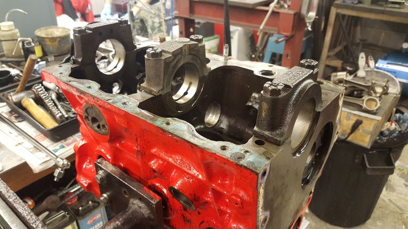
The final check on the block was to use a new cam follower and check the fit in the follower hole. To do this you slide it in while holding one end and wiggle it to check the fit. You are looking for the tightest fit possible, if there is excessive wiggle then when the engine is running it will cause the cam follower to have too much movement. With this done all the caps were removed, the remaining gaskets cleaned off the block and the last two studs and dowel removed. The bores were also measured. The wear below the lip on the bores measured between 3 and 5 thou, as it will be having a +60 offset rebore this wear will be taken out. The bores are being offset at this point to leave more meets between them and so it is ready for any future bigger rebores. The only thing left to do was to remove the water way core plugs (the ones on the front of the block were removed with it off the stand) using a punch and hammer. To remove the oil way plugs the ones on one end were drilled with a 6.5mm drill bit and then a long punch inserted to knock the ones in the other end out. The last two were then punched out from the other end.


That was all we had time for so the block was left with AC for boring, If there are no problems then I will get the new pistons to allow it to be honed to the final size.


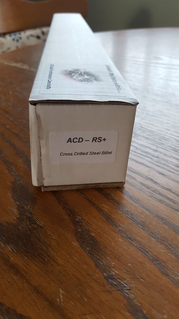
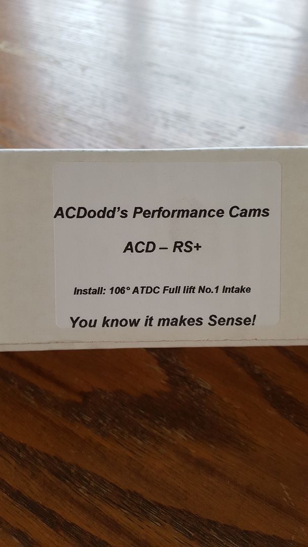
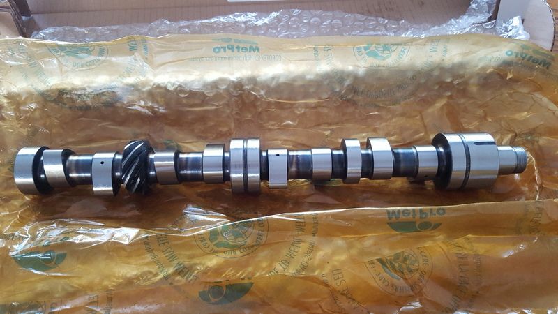
Before I left though I treated myself to an early Christmas present is the form of one of AC's new ACD-RS+ cross drilled steel billet camshafts, this is the first billet cam he has sold.


20151223_125336.jpg

20151223_125342.jpg

20151223_125347.jpg

20151223_125832.jpg


#19 StefanPieter

StefanPieter

    Mini Mad

  • Noobies
  • PipPipPipPip
  • 131 posts
  • Location: Farnborough
  • Local Club: FDMC

Posted 24 December 2015 - 08:44 AM

Once again a great update.

#20 skoughi

skoughi

    One Carb Or Two?

  • Members
  • PipPipPipPipPipPipPip
  • 1,199 posts
  • Location: Lerwick
  • Local Club: Shetland classic car club

Posted 24 December 2015 - 11:43 AM

Great thread and very informative. Makes me wonder if my engine will ever work again after seeing what goes into a proper build.


#21 TehMarchant

TehMarchant

    Super Mini Mad

  • Members
  • PipPipPipPipPipPip
  • 628 posts
  • Location: Caerdydd

Posted 02 May 2016 - 07:28 PM

Anything more happening on this, I love all the detail.


#22 djdanmk

djdanmk

    Stage One Kit Fitted

  • Noobies
  • PipPipPip
  • 81 posts
  • Location: milton keynes

Posted 06 May 2016 - 09:19 PM

Yes it's still going need to get my a** into gear and write it up over the weekend.

#23 djdanmk

djdanmk

    Stage One Kit Fitted

  • Noobies
  • PipPipPip
  • 81 posts
  • Location: milton keynes

Posted 26 September 2016 - 02:52 PM

Right time for an update!!


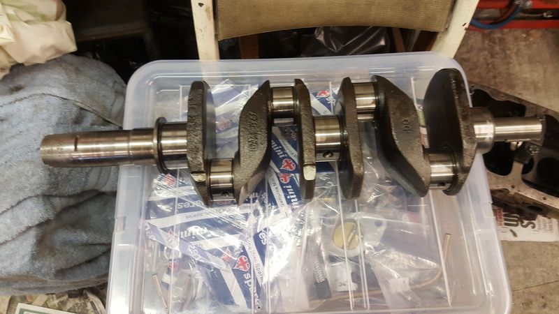
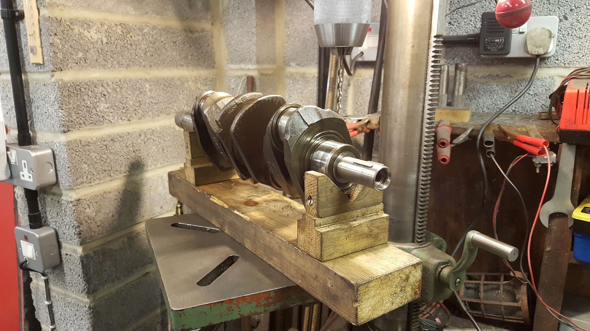
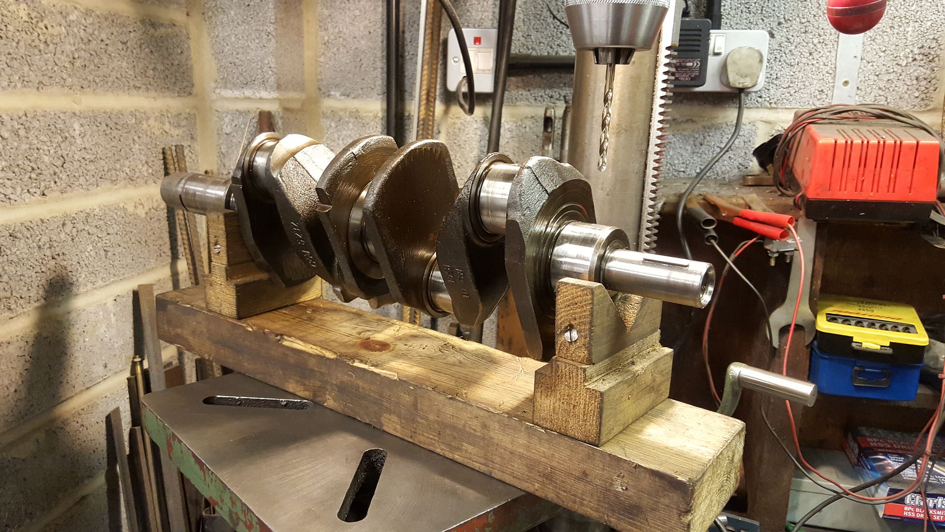
So with the engine fully stripped down the next step was to cross drill the crank mains before it was ground. The reason for cross drilling crank on an A+ engine is that the main bearings only have a oil feed grove on one half meaning the crank only receives oil for half of every revolution.


To do this the crank was placed on the jig below on the pillar drill:

20160103_094221.jpg

20160103_094224.jpg


Then before anything is drilled the crank is marked with a punch on the opposite side to the existing oil drilling. It is important that you get this as near as possible so that you intercept the existing hole. You can be slightly off and use a file to blend the your new drilling into the existing but too far off and its time to find a new crank. Once you have triple checked all your marked positions it is time to bite the bullet and drill using a 5mm drill bit, it is important to use a good quality drill so you get a nice clean hole. You also need to hold the crank to stop it moving while you drill. The outside two are quite easy but to make the middle bearing easier a long series drill bit is very helpful.

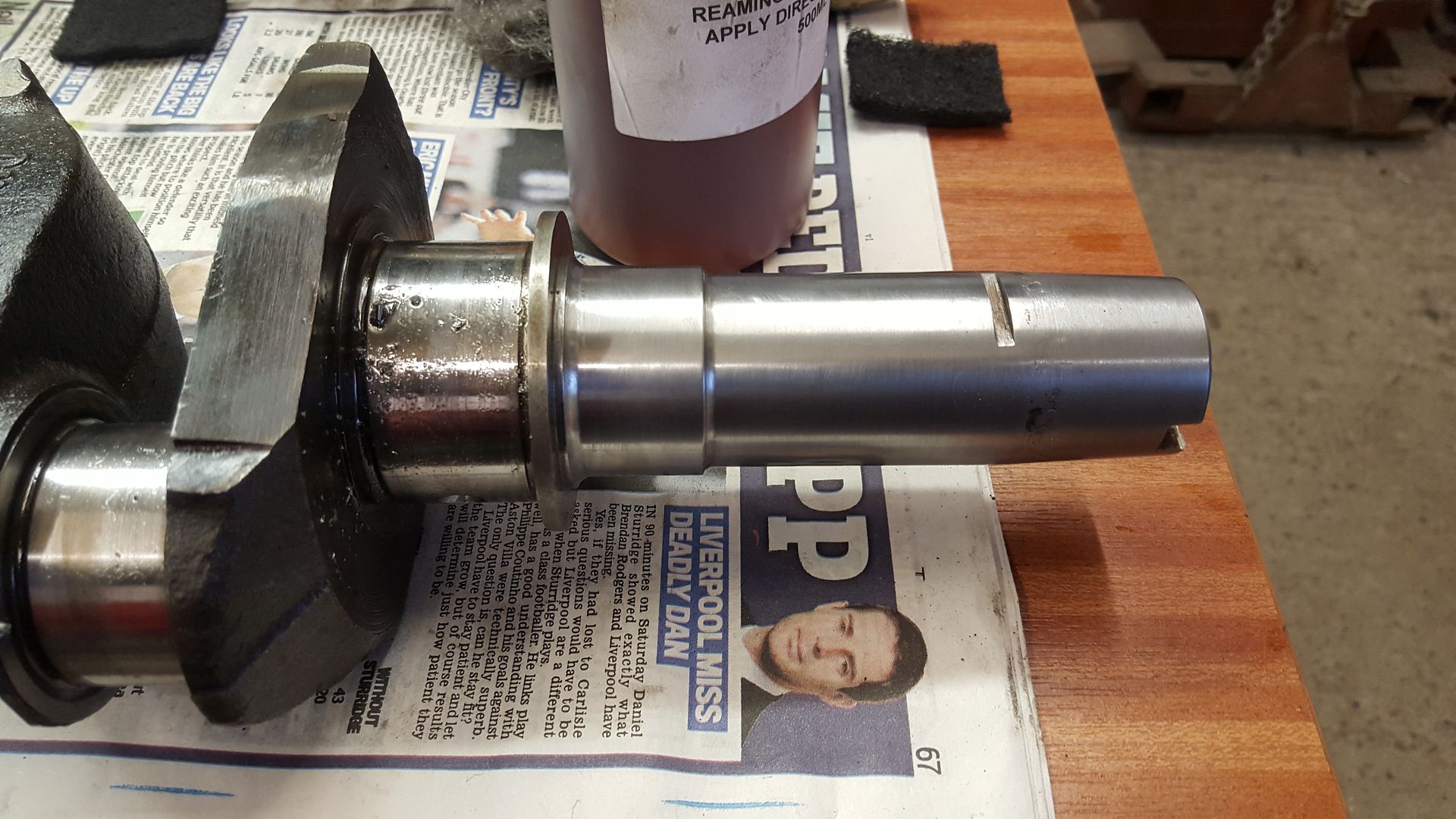
With all hole drilled the centre bearing one was slightly to one side so a small file was used to blend the drilling together leaving no sharp edges then after that a countersunk bit in a hand drill is used to finish off each one. The last job for this crank was to dress a few high spots on the tail with a stone and them with some emery cloth to clean up the crank tail to leave it like this:


20160103_113712.jpg


With the crank ready to be sent off to the grinders it was cleaned and oiled then wrapped up with the centre main cap to they could also check the clearances for the thrust washers and make any adjustments if needed. For this build the crank will not be hardened or balanced but the rods, pistons and flywheel will all be balanced.


So with the crank done it was time to use the rest of the day to finish off the carbs.


As both carbs were built up and jet heights set the first thing was to set the fast idle screws. These were screwed down until they just touch the cam and then half a turn more. With this done it was time to check how the carb dampers felt with oil in the dash pots and to see if they both worked the same. Both dash pots were filled with 20W50 engine oil to start:


20160103_134657.jpg


The pistons were then pushed up by hand to see how they felt. With engine oil the pistons were far too stiff to move so it was emptied and cleaned out and changed for ATF. With this in they both moved much freer but were slightly unbalanced. Before we started modifying the new parts we swapped the dampers round from carb to carb and hey presto they felt the same showing that you cant over look one small detail if you want your twins to act as a pair. Now the carbs were all set up it was time to get them on the manifold:


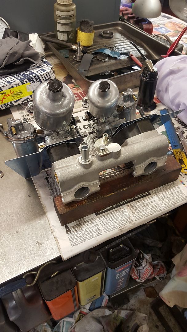
20160103_144518.jpg

20160103_144524.jpg

20160103_150102.jpg


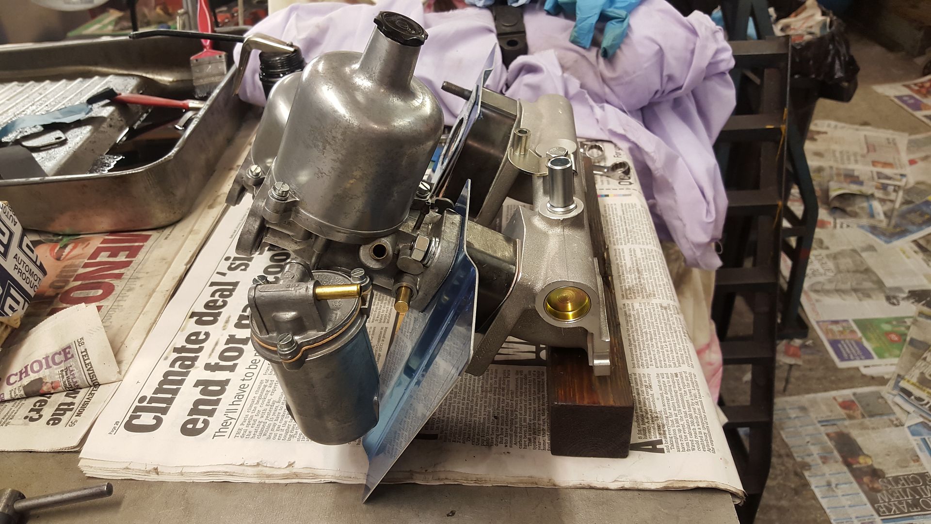
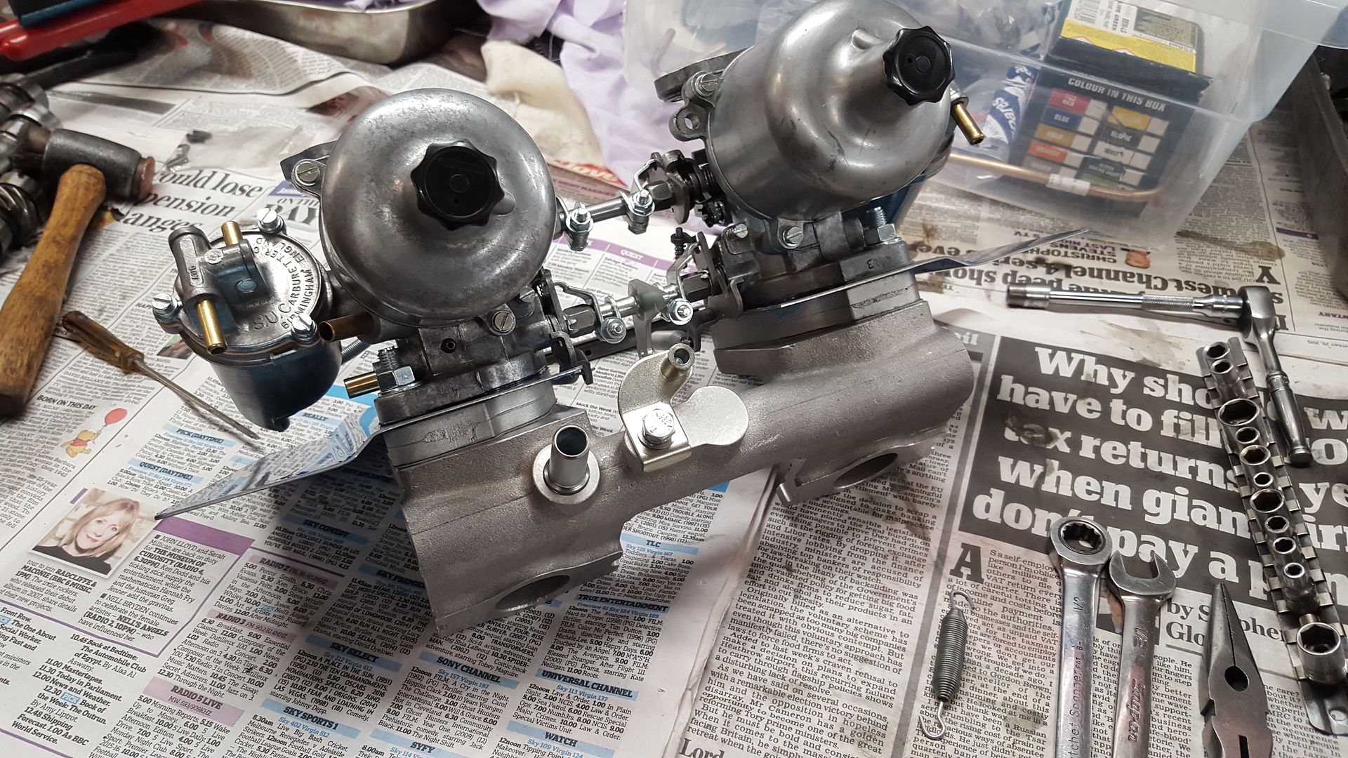
As the black spacers were quite deep in-between engine clubs I got some alloy versions which are shorter. I may use the black ones in time but we will have to see how space in the engine bay is. So with the new spacers the carbs could be finished off an all linkages fitted:
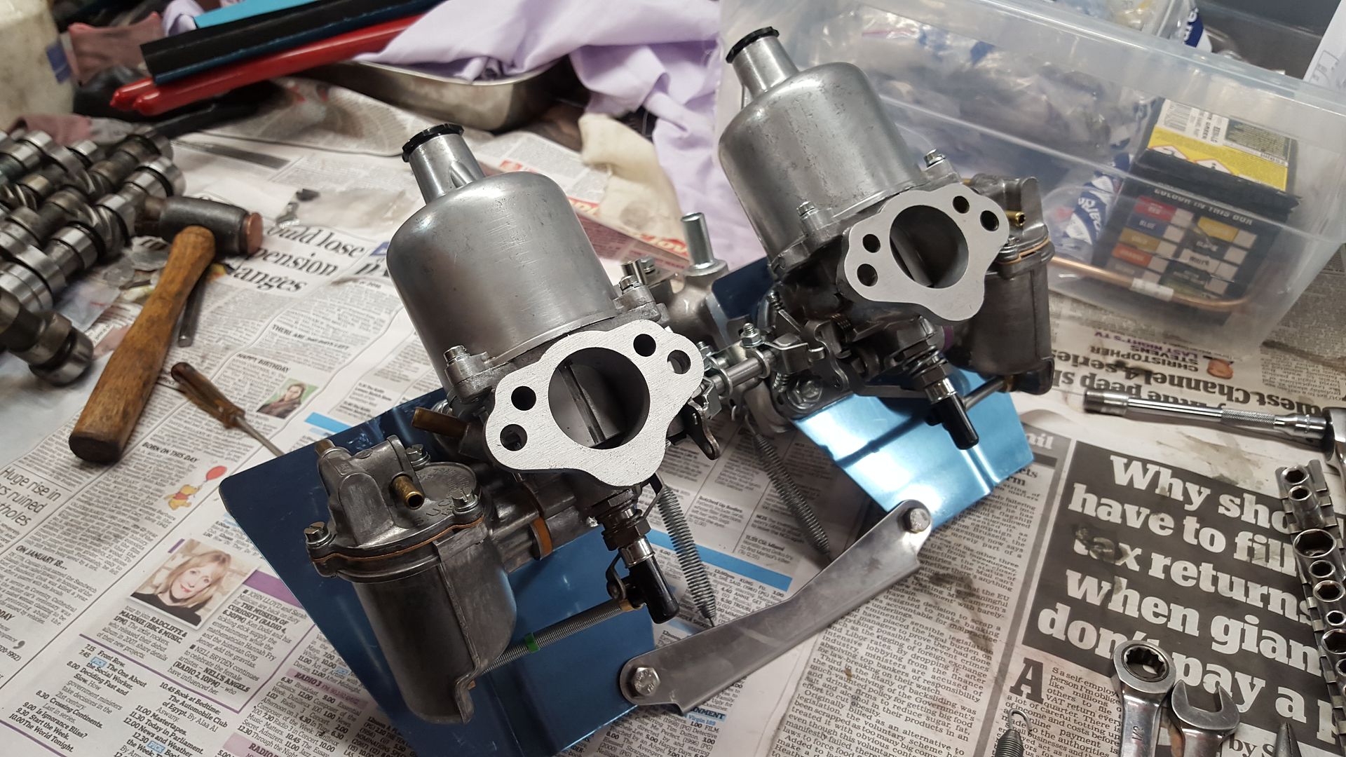
 

20160206_114040.jpg


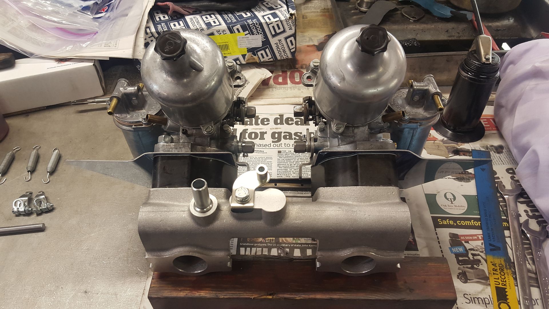
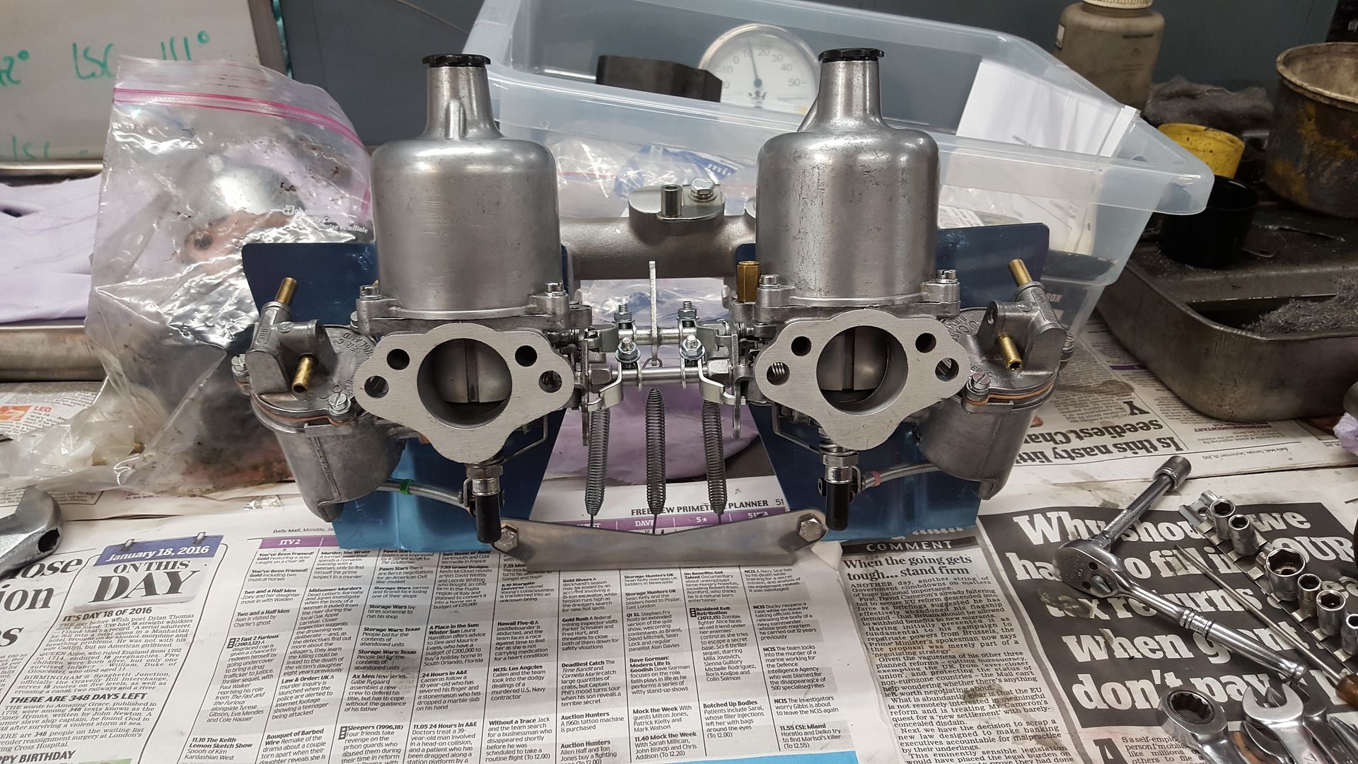
Once the linkages were fitted and the length of each one checked to ensure the correct fit resulting to the carbs coming back off the manifold a few times. All moving parts were well oiled to ensure nothing seizes up over time and then the fun bit of tightening the linkages could be finished. It is important to ensure that both sides of the linkage engage and move each carb at the same time this requires lots of small adjustments and one that was a pain enough on the bench so am not looking forward to the day when im doing it on the car. So with them they were set up and the springs could be fitted meaning I now have a nice pain of rebuild HS4s ready to roll (the blue plastic will come off the heat shield before fitting just don't want it getting scratched for now):
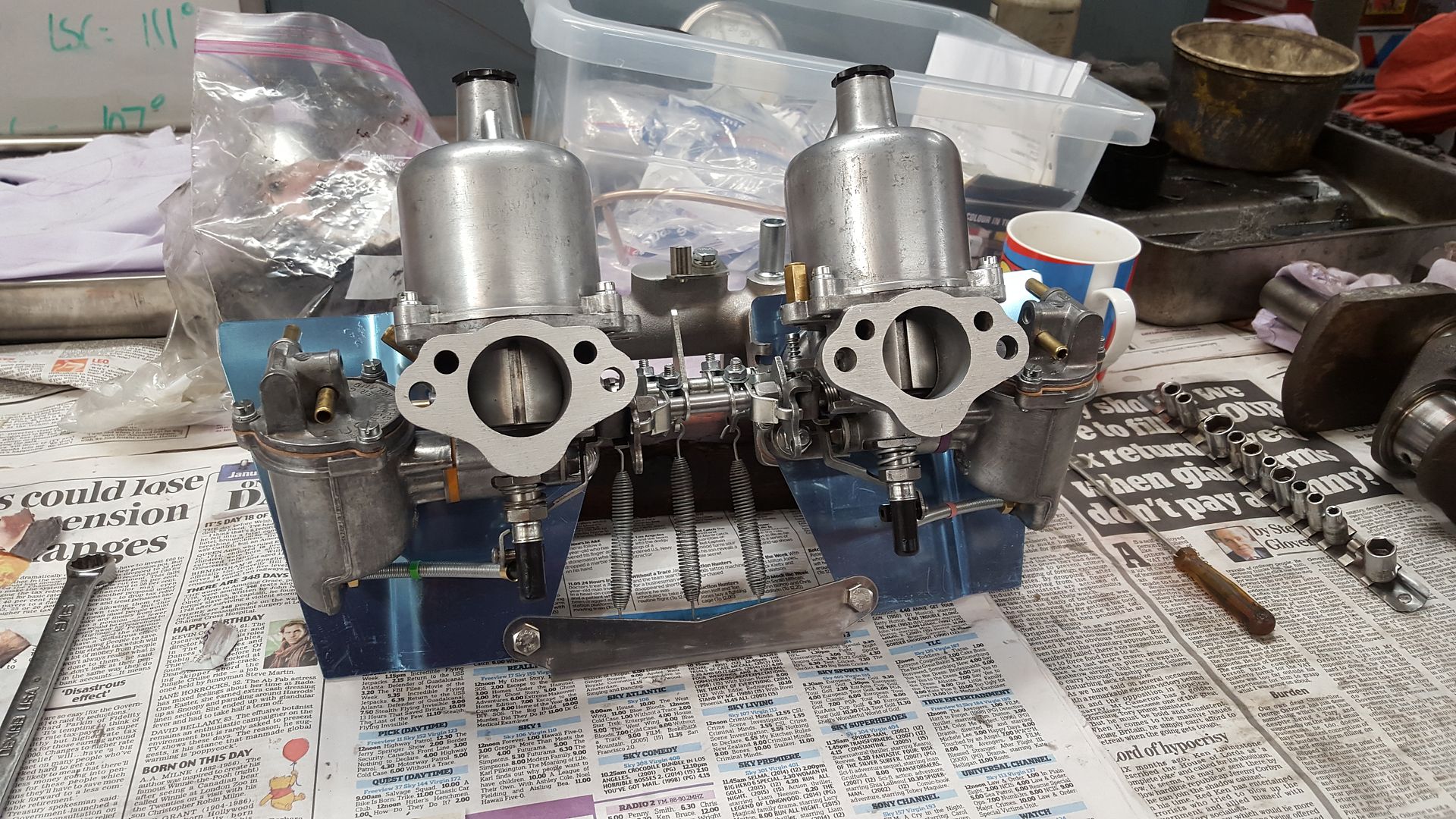
 

20160206_114048.jpg

20160206_145922.jpg

20160206_152109.jpg


The only other job I want to do to them is polish the dashpots when I get a spare couple of hours at home. And before being fitted they will be treated to a ITG filter with MED stub stacks.



#24 ryomini

ryomini

    Super Mini Mad

  • Members
  • PipPipPipPipPipPip
  • 583 posts
  • Location: Hiroshima

Posted 26 September 2016 - 03:07 PM

Lots of very nice pix thanks for sharing all the details


#25 djdanmk

djdanmk

    Stage One Kit Fitted

  • Noobies
  • PipPipPip
  • 81 posts
  • Location: milton keynes

Posted 26 September 2016 - 03:35 PM

No problem there are more updates to come tonight once all the photo uploads from my phone are finished and iv got some work done instead of looking at mini stuff. Planning on putting a spread sheet up at some point to show all of the costs involved as well.


#26 djdanmk

djdanmk

    Stage One Kit Fitted

  • Noobies
  • PipPipPip
  • 81 posts
  • Location: milton keynes

Posted 26 September 2016 - 10:02 PM

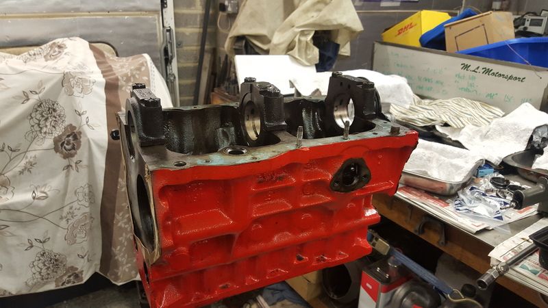
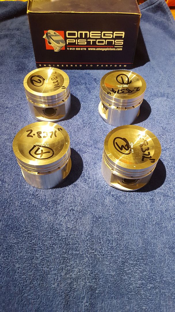
So with the carbs done and the crank ready to be sent off to be ground the block was left with AC to be bored out. As I hadn't brought the pistons at this stage AC bored the block to ensure there were no problems with the block encase we had to go for a bigger bore. Luckily there were no problems so a set of omegas were ordered and sent to him so the final boring could be done. The block was offset bored to maintain the thickness between the bores.


The omega pistons really are nice to look at:


20160926_234641.jpg


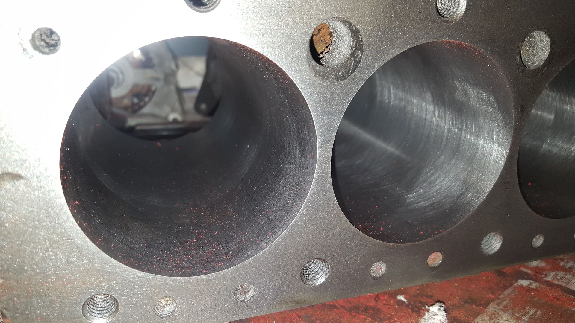
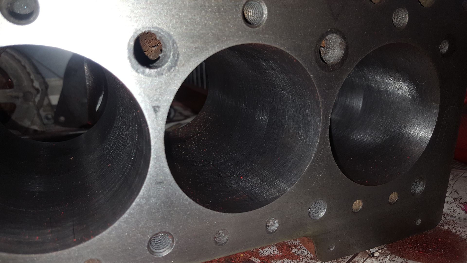
So here's a couple of pics of the freshly bored and honed block (the small amounts of dirt are from where I took these pics after cleaning the paint off)


20160409_140513.jpg

20160409_140520.jpg


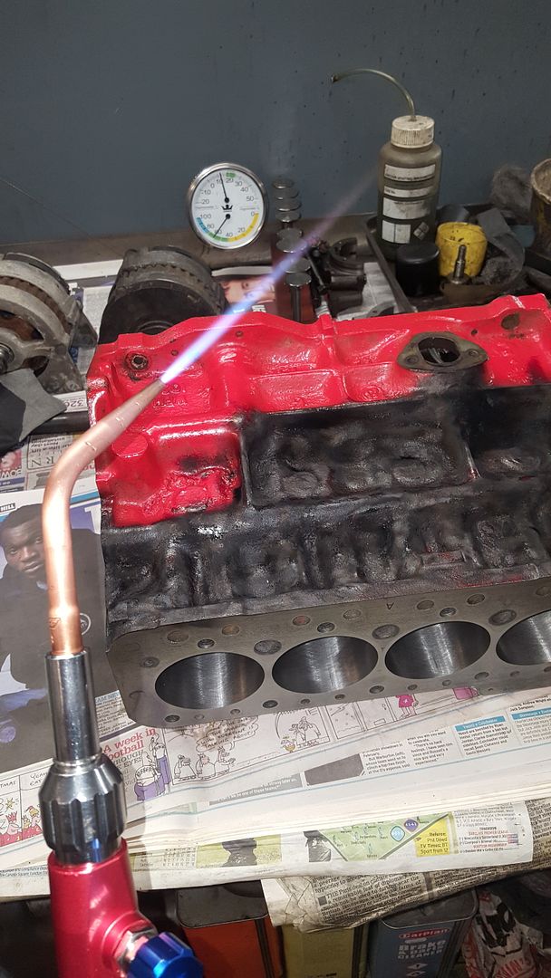
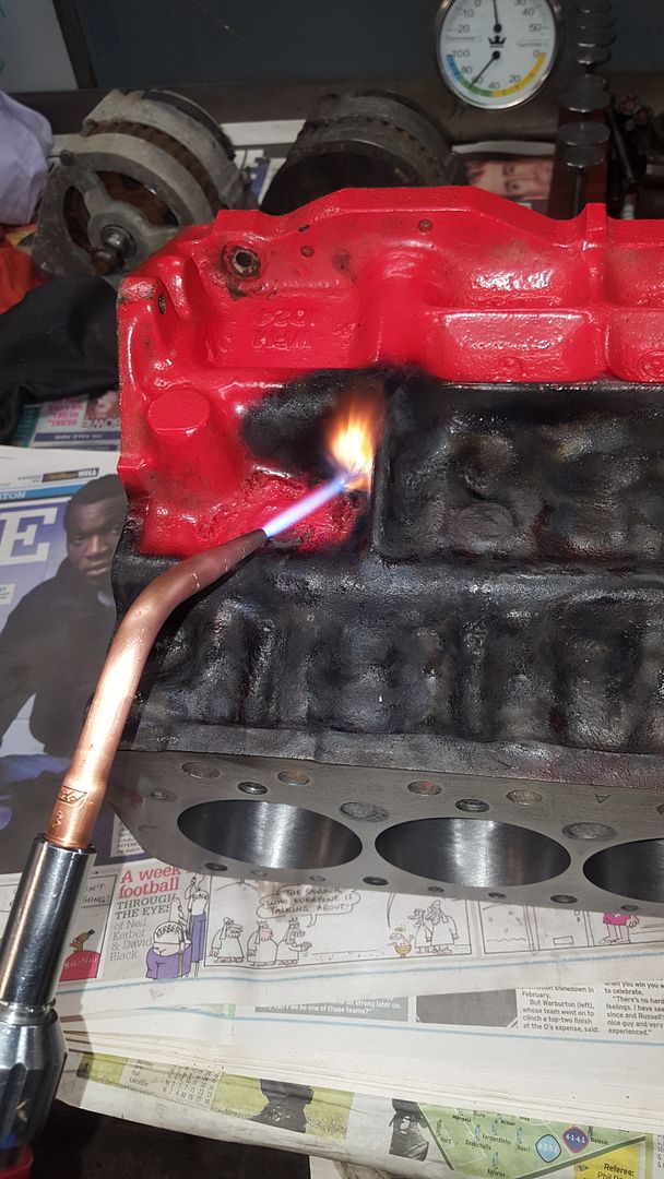
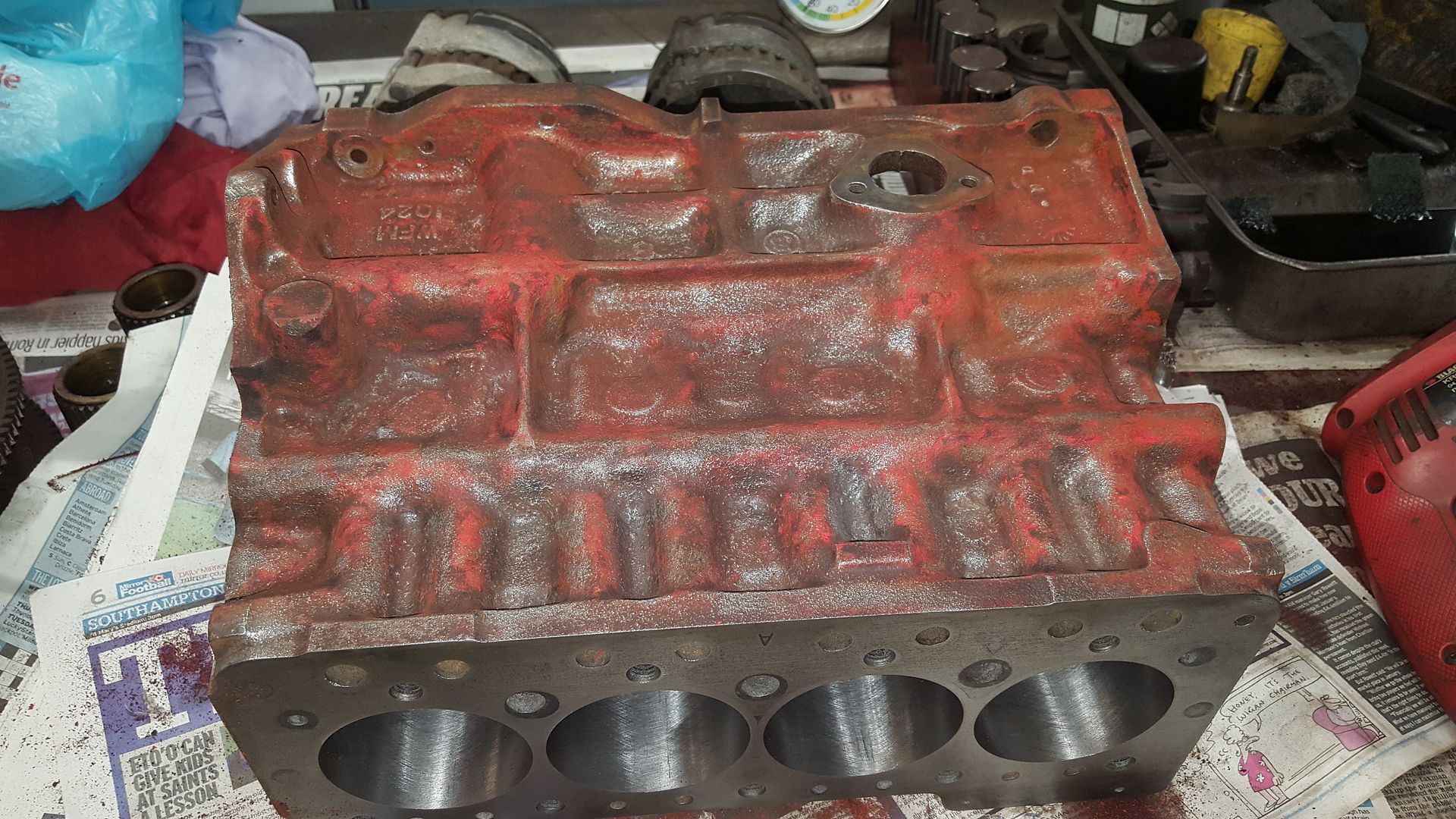
So the block was now ready for all of the old paint to come off. To make this easier a oxy propane torch was used to oxidise the paint and start to loosen it up before a wire brush in a drill was used to clean it all off. The paint was quite thick so this took a couple of goes to get it cleaned up. The oxy propane torch is a great bit of kit and im looking forward to getting my own set up.


20160409_111233.jpg

20160409_111240.jpg

20160409_140506.jpg


The flame is hot enough to burn the paint but as it is very localised not a lot of heat goes into the block avoiding any potential problems.

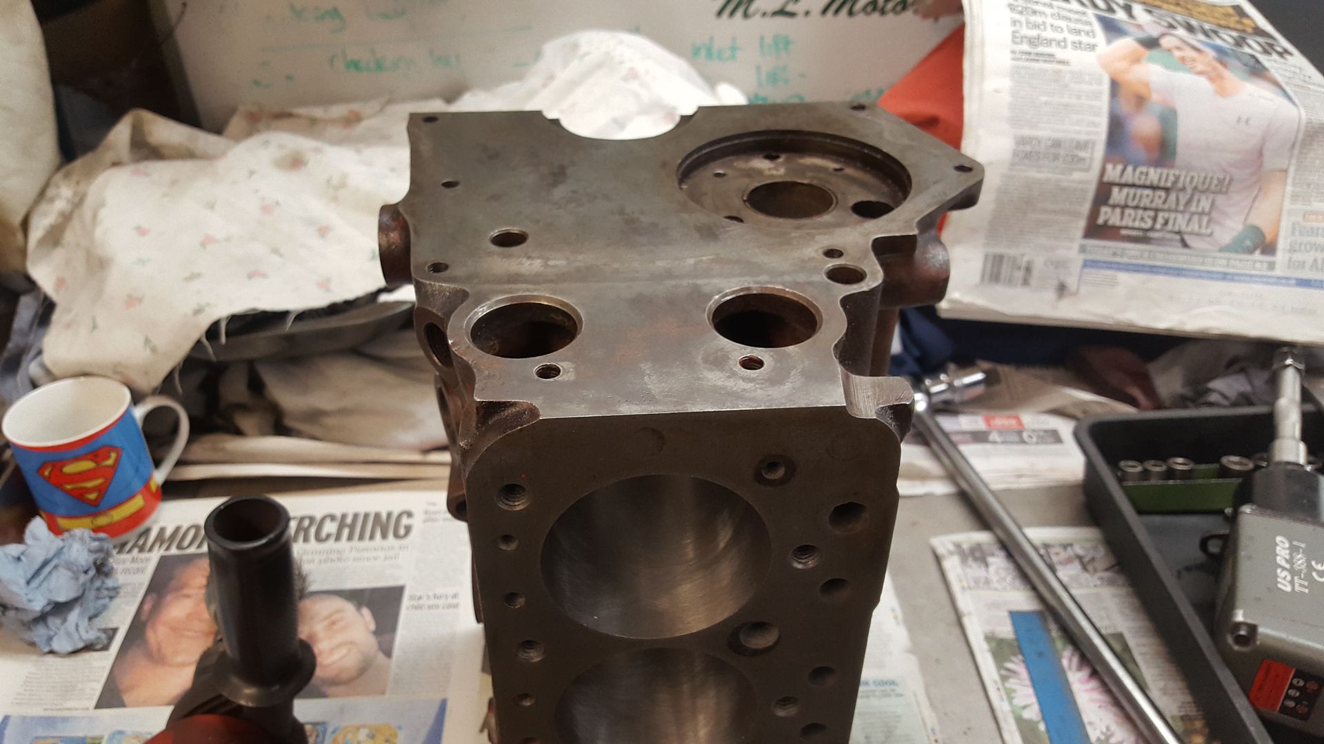
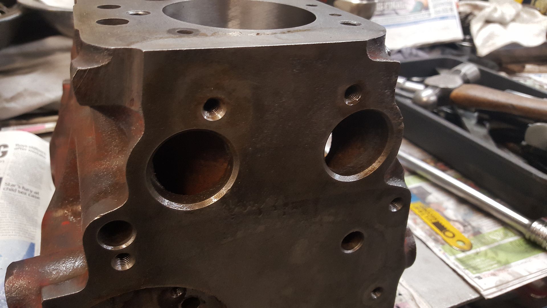
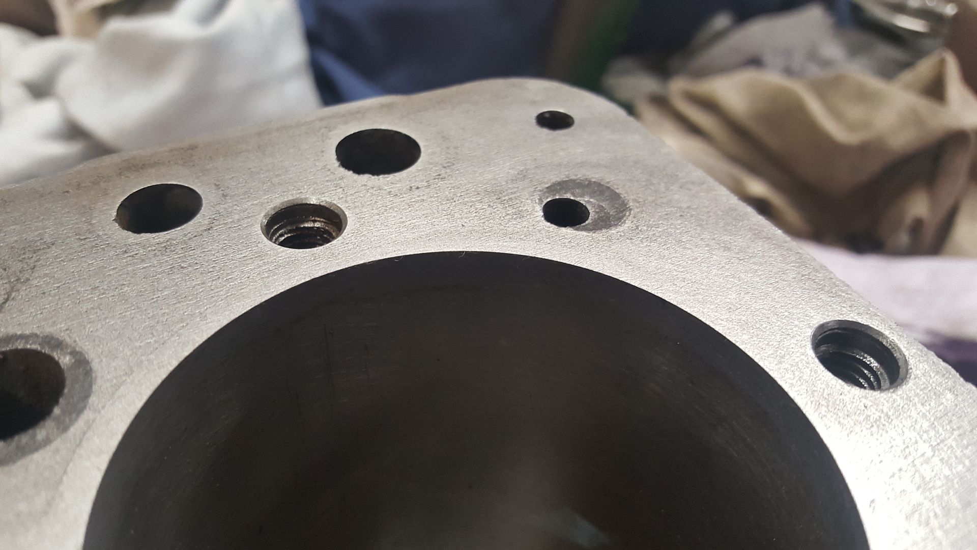
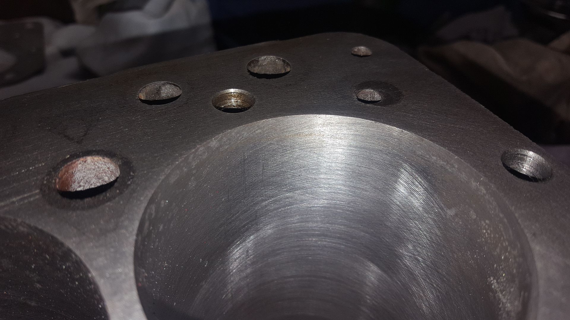
The next steps for the block was to clean out all of the threads with a tap and lightly countersink the holes:


20160618_110233.jpg

20160618_112836.jpg

20160618_115105.jpg


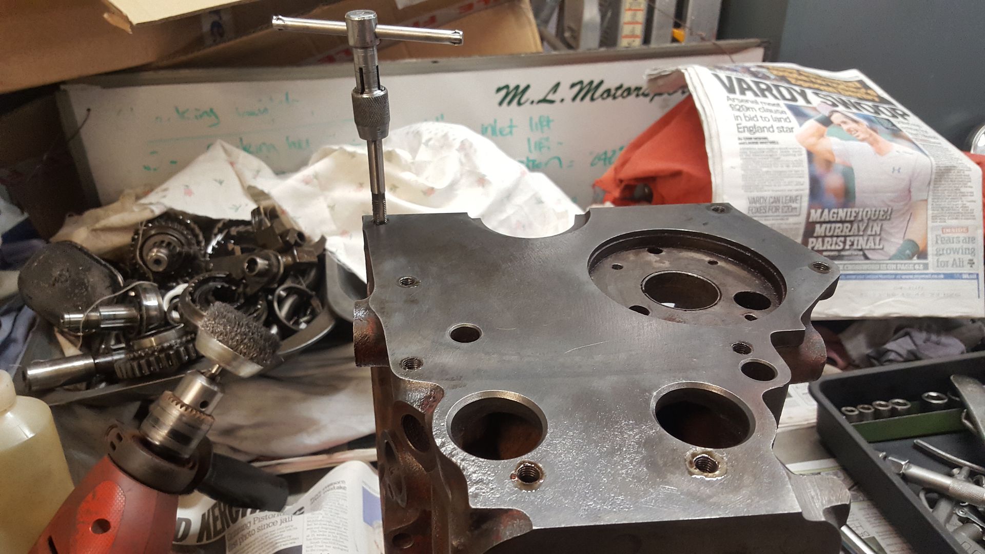
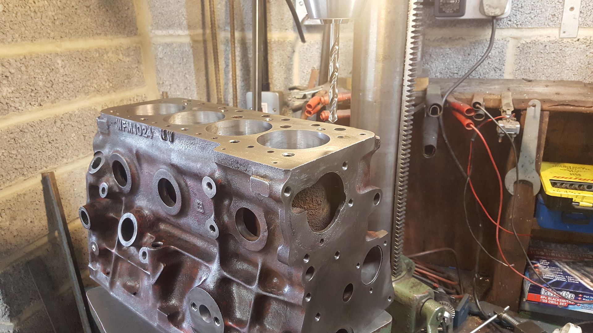
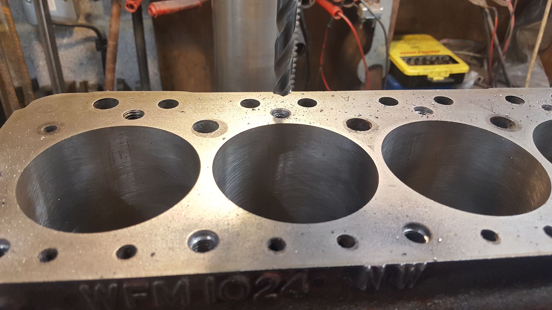
The last job for the block at this stage was to drill out for the 10th and 11th studs as this will be a higher performance engine. A 1275 head gasket was placed on the block to act as a guide to mark the position of the 2 studs. With both marked they were centre punched in the middle of both and then it was off to the pillar drill. When drilling above water pump end you have to be carful not to drill to deep or you will enter the water way below.


20160618_154227.jpg


Once they were drilled they could be taped first using the tap in the pillar drill chuck turned by hand to start the thread off square. The final part for the block this day involved removing the top 1 or 2 threads from each stud hole and lightly chamfering them. This prevents the threads pulling up when the head is tightened down ensuring a good fit and seal of the head gasket.


20160618_163352.jpg

20160618_164412.jpg

20160618_164424.jpg


With that done it was the end of the day so the block was cleaned off and then oiled up to prevent rusting.


Edited by djdanmk, 26 September 2016 - 10:53 PM.


#27 djdanmk

djdanmk

    Stage One Kit Fitted

  • Noobies
  • PipPipPip
  • 81 posts
  • Location: milton keynes

Posted 26 September 2016 - 10:39 PM

So now with all the past updates out the way I can get onto the latest and current ones.


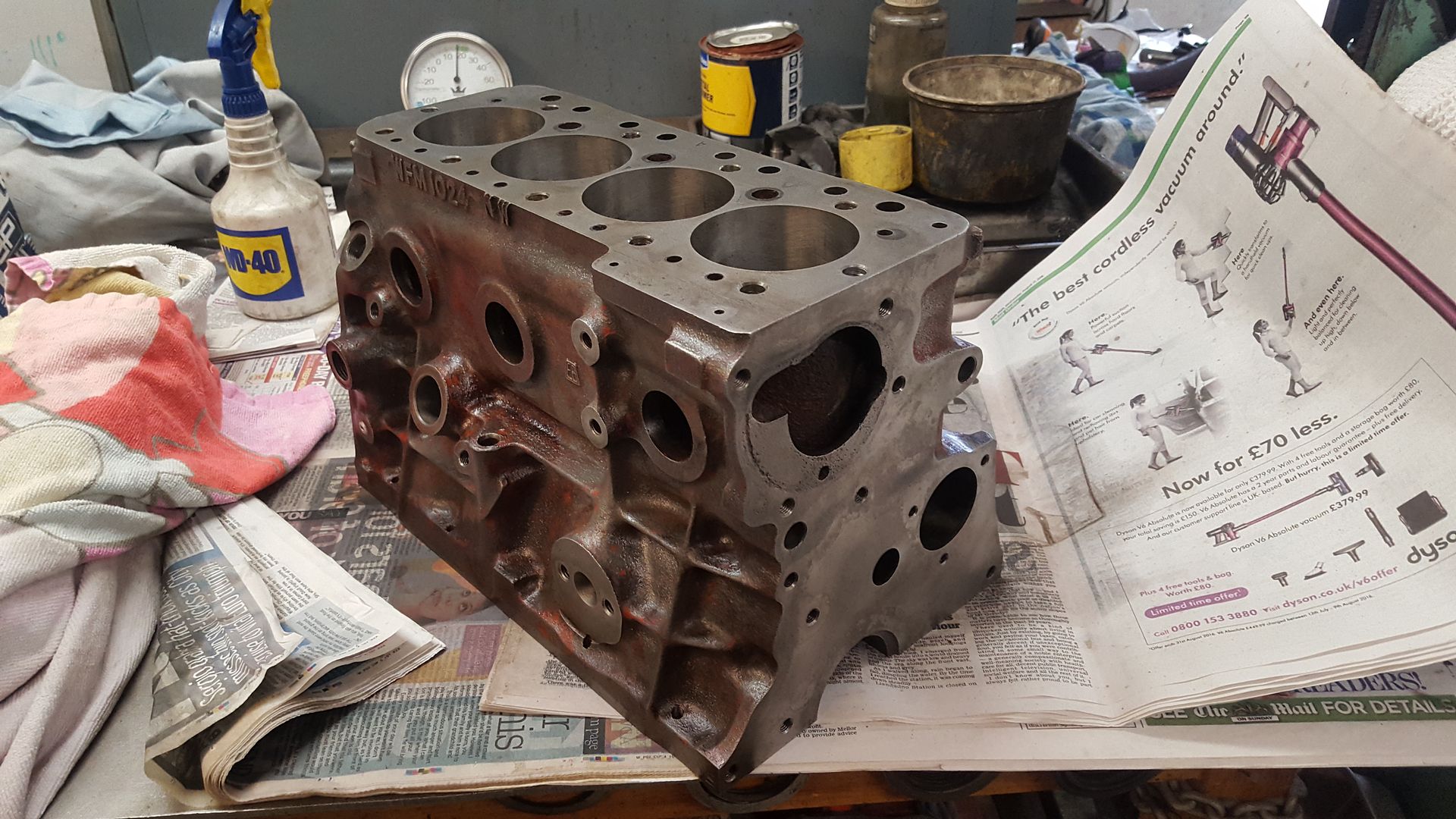
As the block at this stage was looking rather manky from drilling, tapping, paint removal ect it was time to get the paraffin and brush to give all the surfaces a good clean. Once every surface had been covered and scrubbed the whole block was given a good going over with a ton of break cleaner dried with the air gun and came out looking like this:


20160924_140603.jpg


Much better but this is only the first rough clean which means the block is now ready for the dry build stage meaning the piston to deck height can be checked and then the block sent off to get machined to clean up the face/make any adjustment needed to get the correct compression ratio. But before any dry build more parts will be needed.


One thing I have learnt from engine club that any engine build is mostly cleaning and measuring. Without this attention to detail you cant get the end result you want, even new items need to be checked as you cant assume that they will fit out the box.


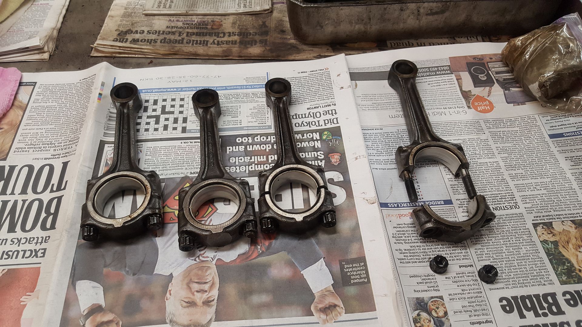
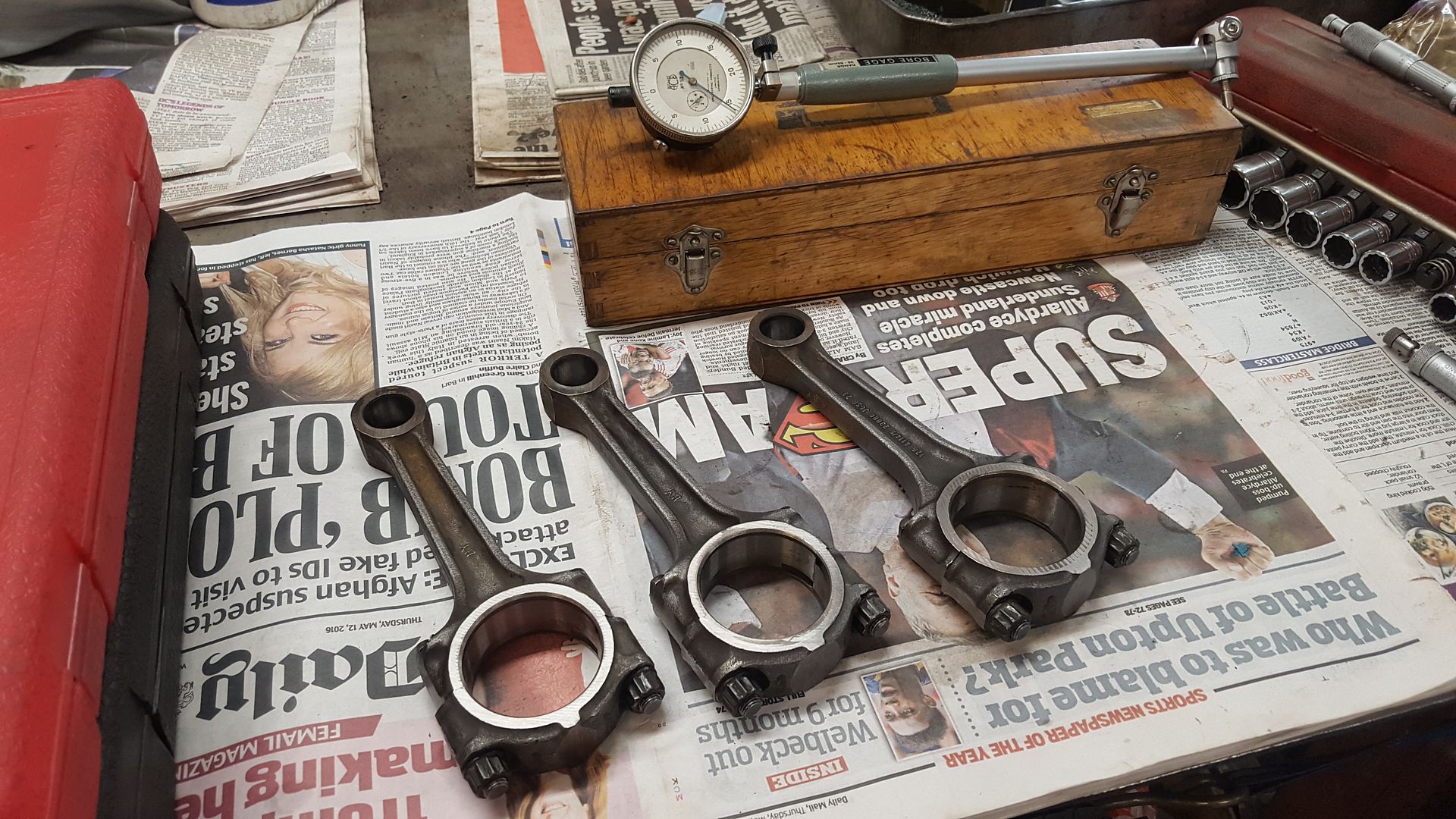
As I didn't have the parts to preform a dry build yet and the rods hadn't been looked at yet it was time to move onto them.


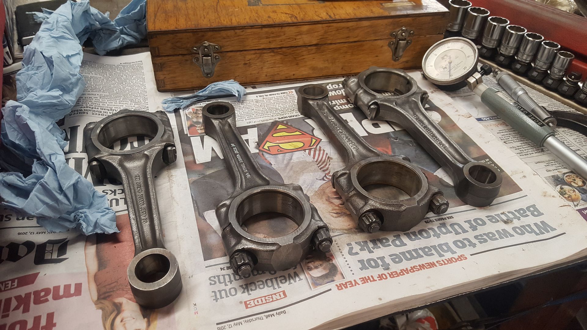
As the rods hadn't been touched since they were removed from the block they were looking rather manky:


20160924_141255.jpg


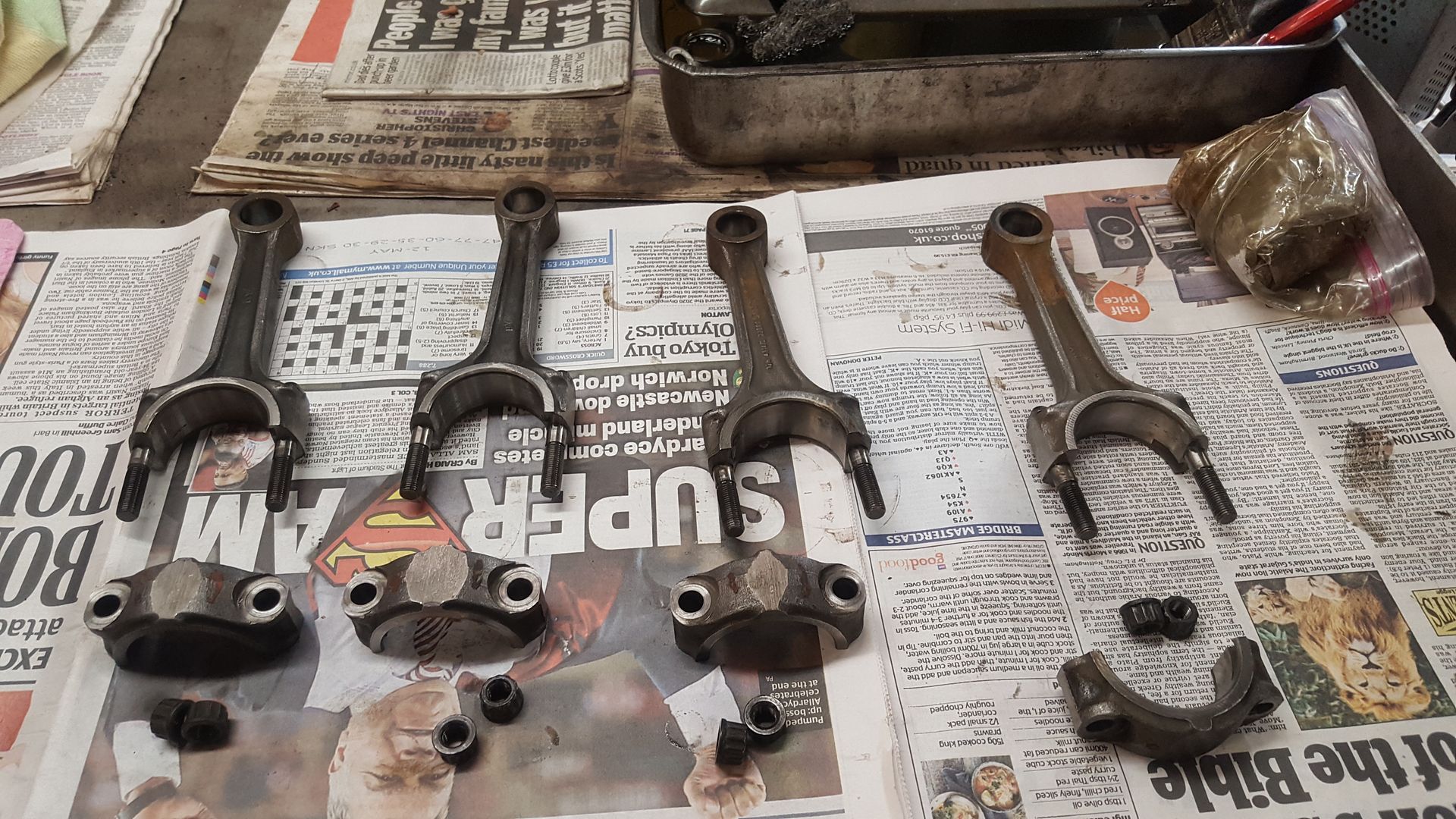
So the caps were removed keeping them with their correct rod old bearings removed and sent to the scrap bin and all given a quick degrease:


20160924_142034.jpg


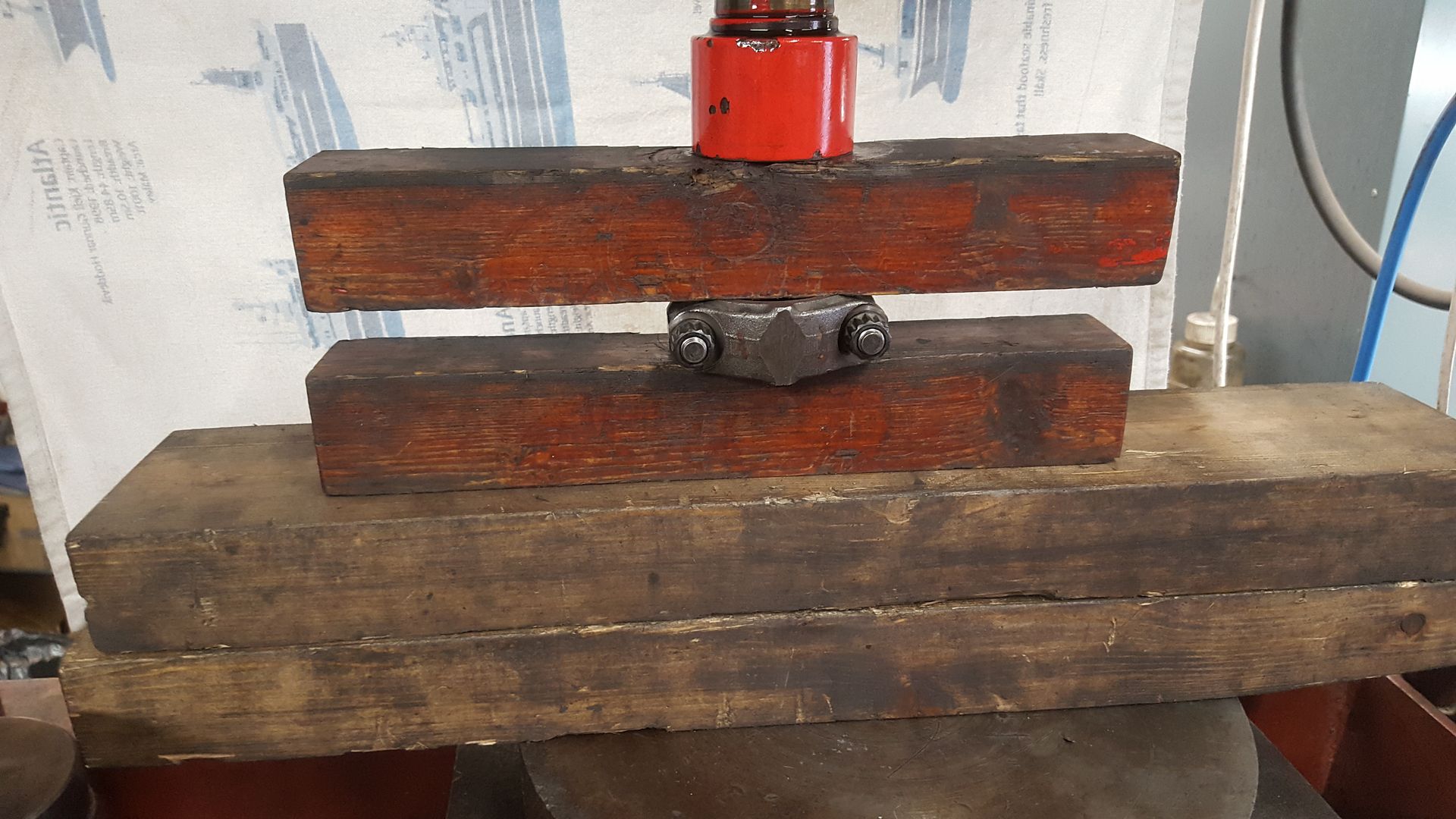
The caps were then put back on their rod and put in the press so they could be tightened to 34flb ready for measuring:


20160924_143138.jpg


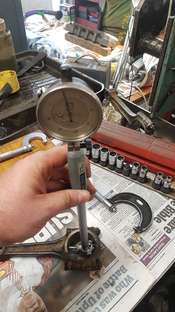
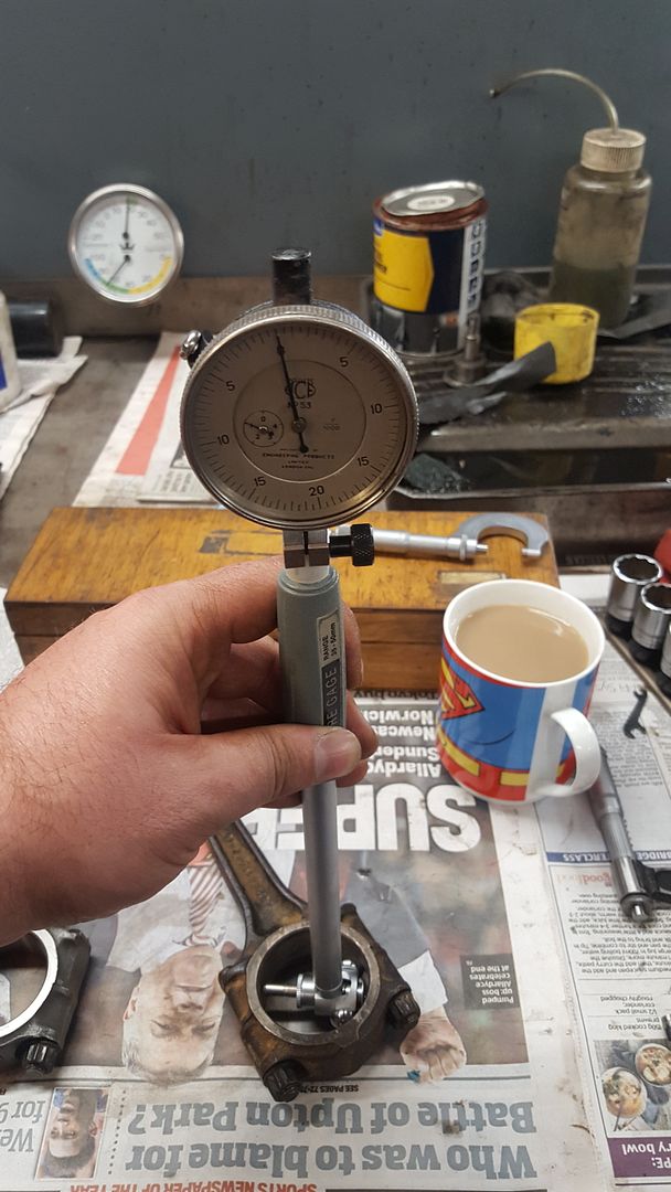
First all the small ends were checked with a bore dial gauge to ensure the correct interference fit of the gudgeon pins could be achieved and none will make a bid for freedom in the future a minimum of 1000th of interference is needed here. 3 out of the 4 rods passed this test but as 1 didn't cut the grade it was rejected.


20160924_152133.jpg


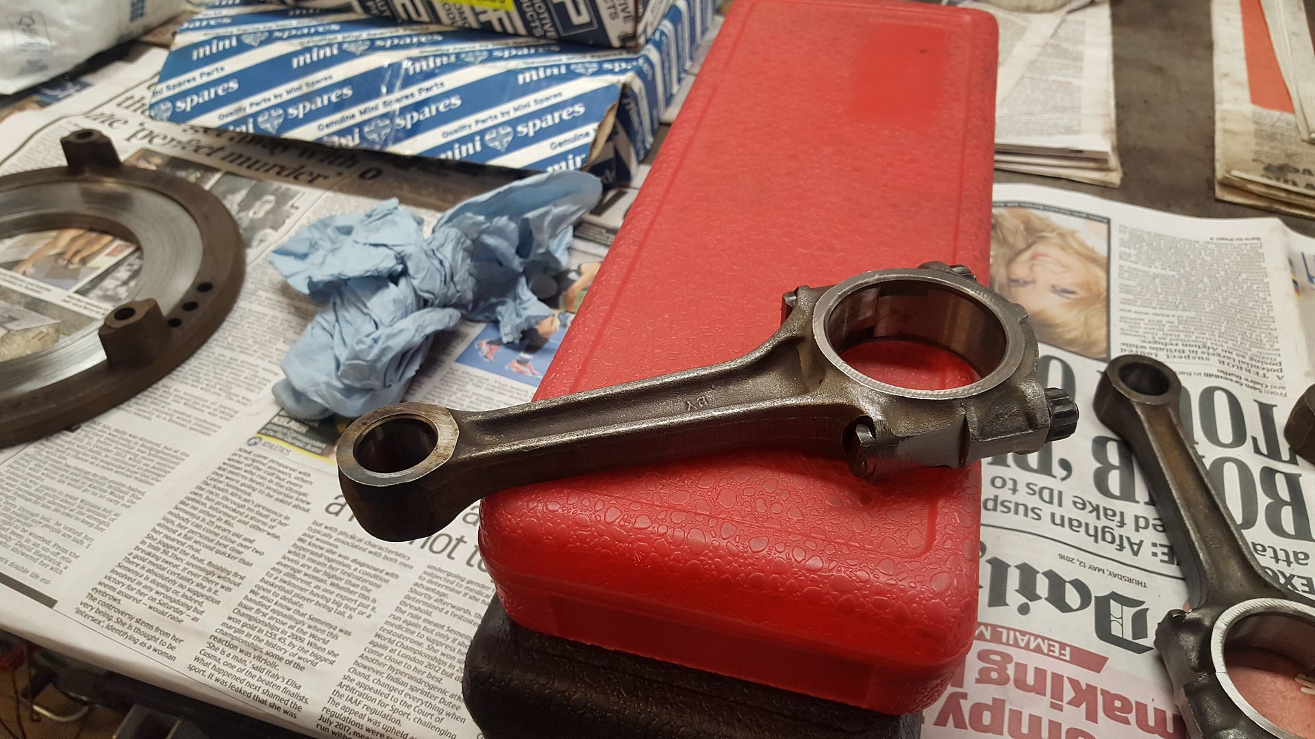
If you just gave them a quick visual then you would never spot these small issues and end up with a much worse problem later on. Next the big ends were all checked to ensure they were the correct size and still round. Luckily all of the 3 remaining rods were in good shape. So this meant I was now needing 1 more rod to complete the set. After going through all of AC's spare rod stash I luckily found one that was close enough in weight to the others. This rod was then checked in the same way. First the small end then the big end all after cleaning. 


20160924_152100.jpg

20160924_155103.jpg

20160924_155121.jpg


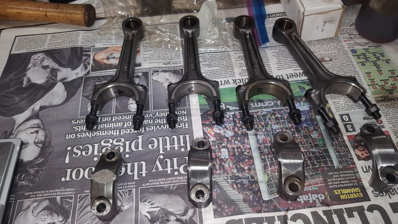
Another check when the caps are put on the rods is to check the machining marks all line up. This ensures all the caps are on their correct rod and have never been moved around. All of the rods will be refaced before fitting as a couple show sings of rubbing during the past.


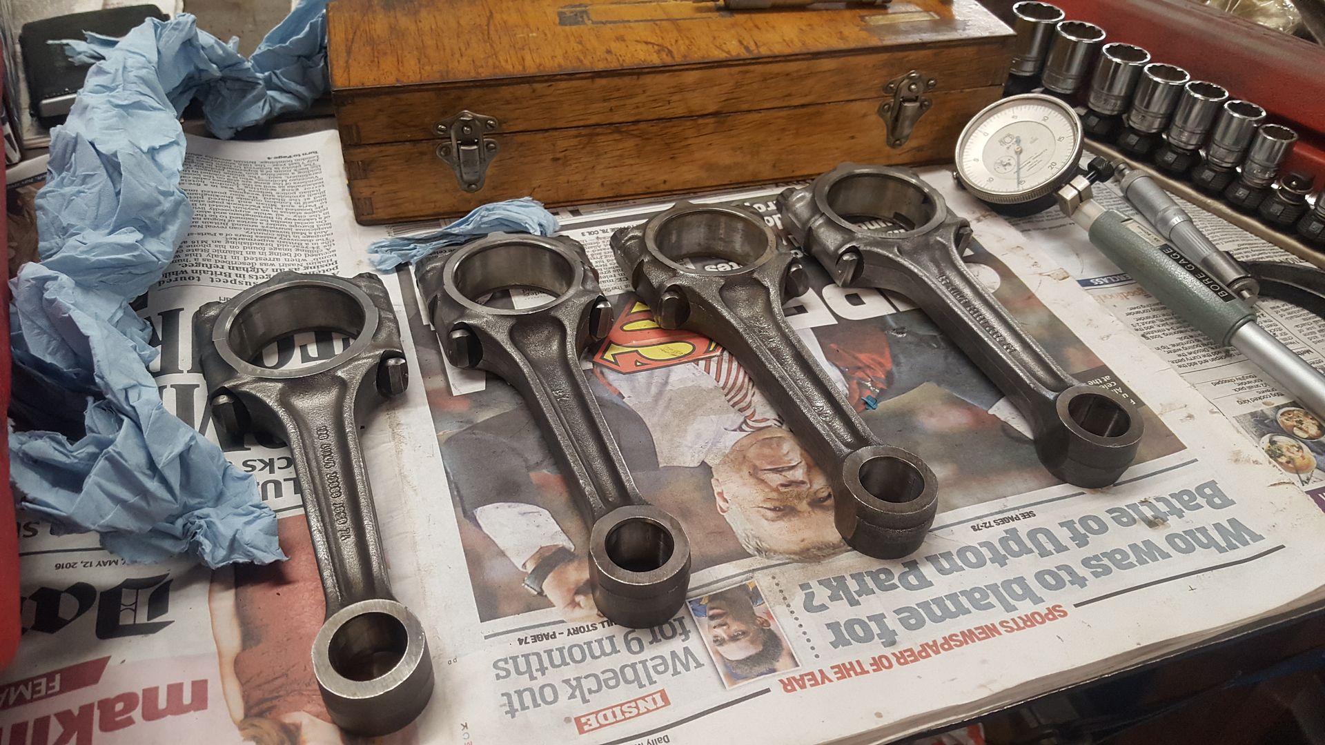
The rods were then given a good clean up with a wire cup brush to bring them up like this:


20160924_162607.jpg

20160924_162617.jpg


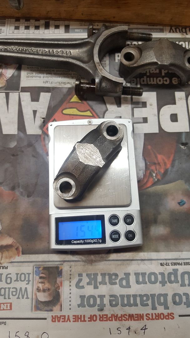
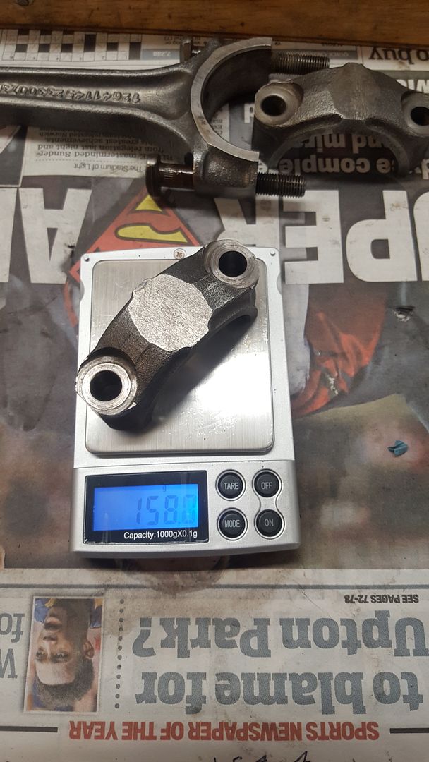
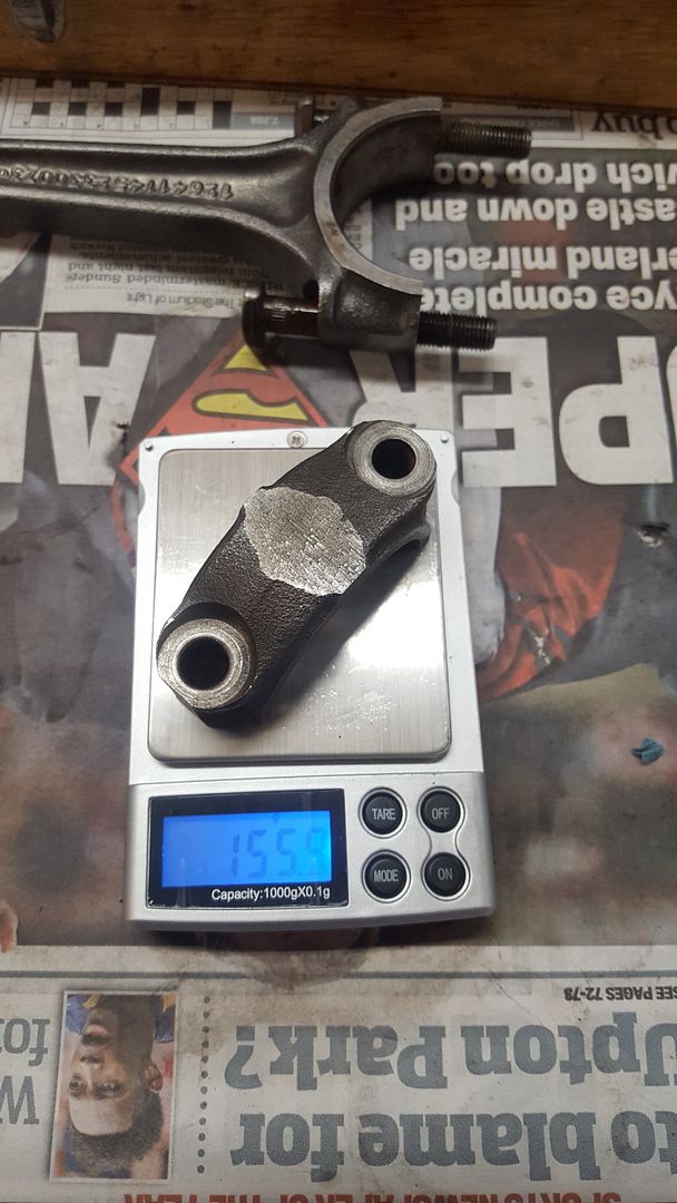
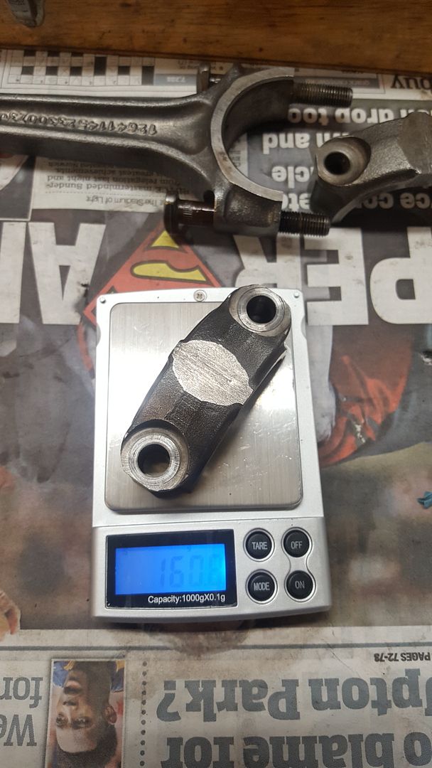
As time was getting on by this point the last job was to weigh each cap to see how they varied in weight. Next time they will all be balanced. Turns out I have a 6g difference between the lightest and heaviest to correct:


20160924_164827.jpg

20160924_164834.jpg

20160924_164841.jpg

20160924_164848.jpg


#28 ACDodd

ACDodd

    Up Into Fourth

  • Mini Docs
  • PipPipPipPipPipPipPipPipPip
  • 2,654 posts

Posted 28 September 2016 - 06:33 PM

Loving you work Dan!

Ac

#29 Carlos W

Carlos W

    Mine is purple, but I have been told that's normal

  • TMF+ Member
  • PipPipPipPipPipPipPipPipPipPipPip
  • 10,110 posts
  • Location: Sittingbourne, Kent

Posted 30 September 2016 - 07:38 PM

Mine was 6g as well.


#30 djdanmk

djdanmk

    Stage One Kit Fitted

  • Noobies
  • PipPipPip
  • 81 posts
  • Location: milton keynes

Posted 12 October 2016 - 10:34 AM

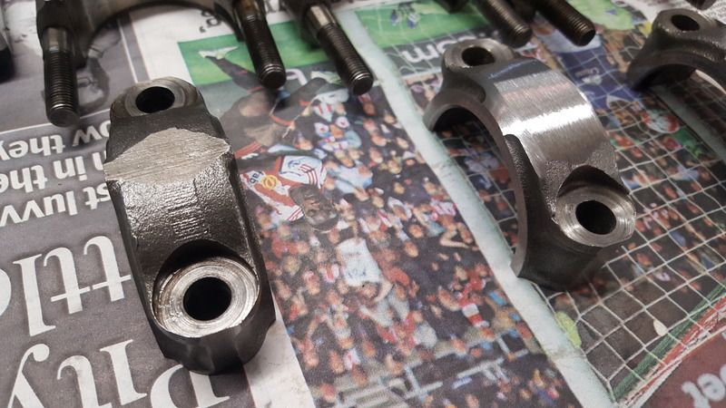
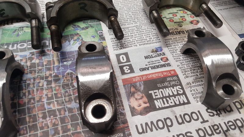
So it was time to start to balance the rods. The heaviest cap was first up for some metal to be removed. Using a linisher metal was slowly removed from the cap starting with the ears on each side then across the middle being extra careful not to damage the seating faces for the rod bolts/nuts. When doing this it is important to think about fatigue as in use the rods will be under load and as this engine will see some heavy right foot action we don't want to carry out any prossesses that will introduce weak/failure points.

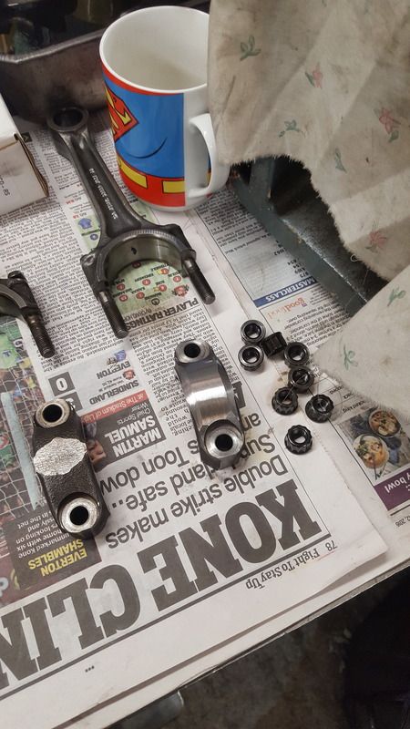
To this end when removing the metal it is important to hold the cap length ways with the belt so metal is removed in the same direction going from hole to hole unlike from the factory where metal was removed at 90 degrees to this. This can be seen in the pictures below, the one on the left being a factory cap as it came off and the one on the right being lightened.


20161008_144743.jpg


So with 6G of metal removed from the first cap it looked like this:


20161008_124459.jpg


With one down it was time to get the next two done:


20161008_144737.jpg

20161008_144740.jpg 

20161008_144743.jpg


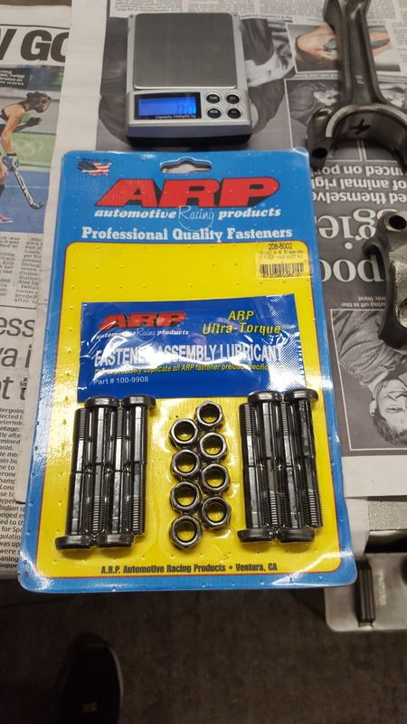
As the engine will see a hard time ARP rod bolts will be used to hopefully reduce the chance of any rod failures:


20161008_145036.jpg


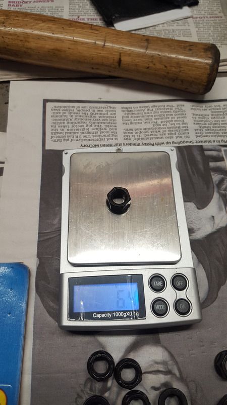
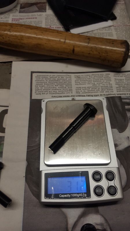
Next all the bolts and nuts were weighed but as these are made to very high tolerances they all weighed the same:


20161008_145241.jpg

20161008_145418.jpg


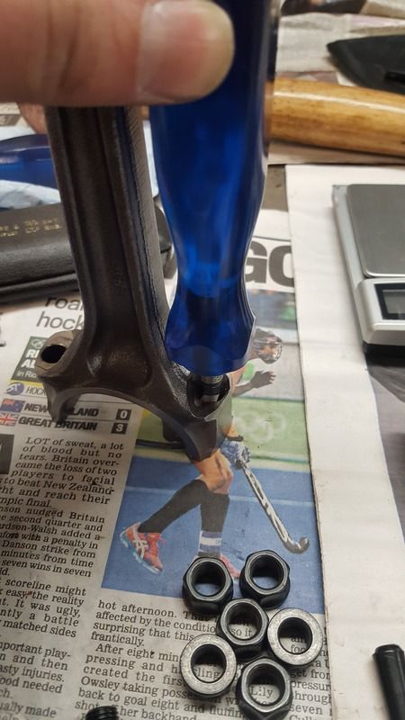
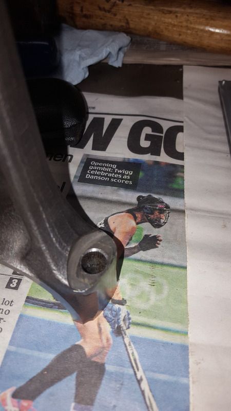
Before the rods could be weighed and balanced the bolts and nuts need to be fitted so first all of the holes were inspected to check the chamfer was ok to prevent stress points causing the bolts to snap at a later date. A couple of the rods needed a little attention to increase their chamfer and this was done by hand and any small burs removed with a needle file.


20161008_152820.jpg

20161008_152837.jpg


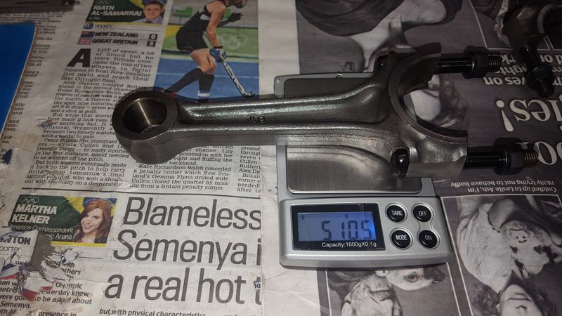
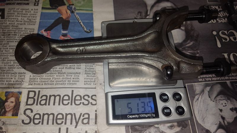
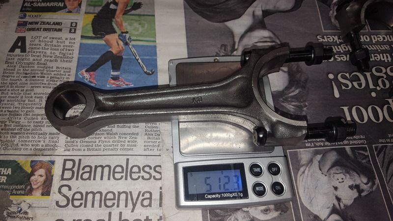
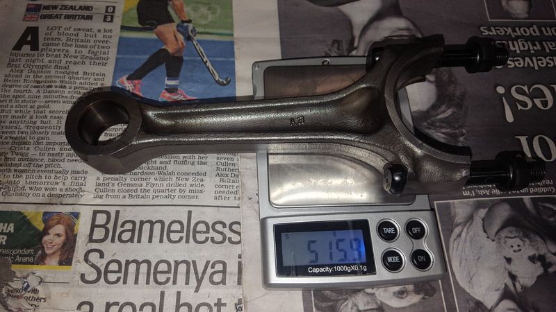
So next up it was time to fit the bolts and weigh the rods. When weighing them it is important to always put the rods on the scales in the same way each time.


20161008_154131.jpg

20161008_153324.jpg

20161008_153341.jpg

20161008_153405.jpg

20161008_153429.jpg


So next up  metal was removed from the small ends to bring all of the rods to the same weight once again ensuring that it is removed in the right direction to prevent fatigue.


20161008_161252.jpg


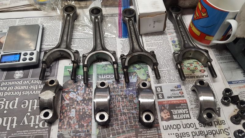
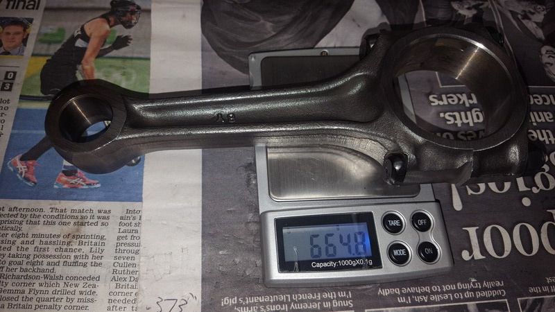
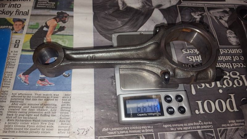
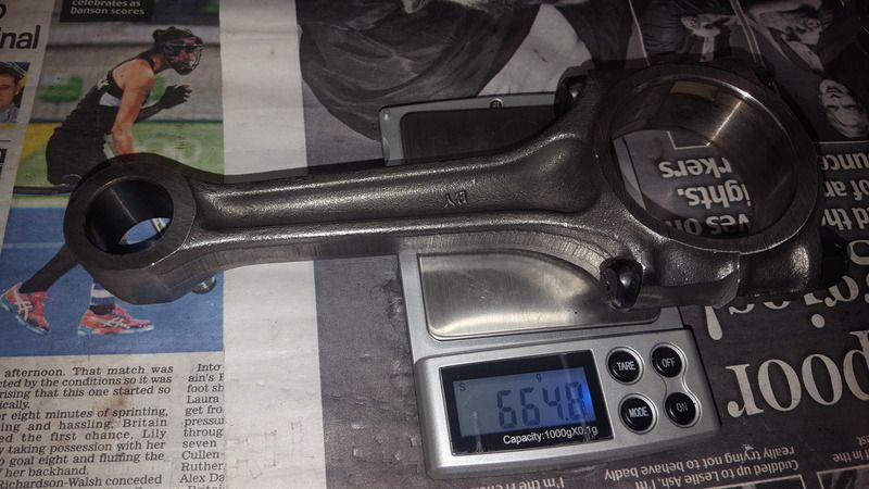
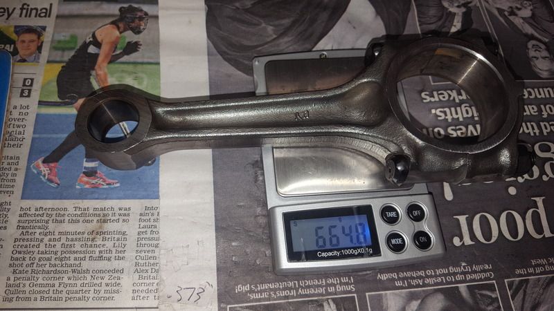
With all the rods done they were all given a good clean up and the small ends cleaned to ensure that when the pistons are fitted the colour of the metal can be seen clearly as they are heated. They were then all bolted together and the faces given a quick clean on the linisher to ensure all the faces were flat. With this done they were all weighed and now came in at 664.8g.


20161008_162931.jpg

20161008_162943.jpg

20161008_162958.jpg

20161008_163009.jpg


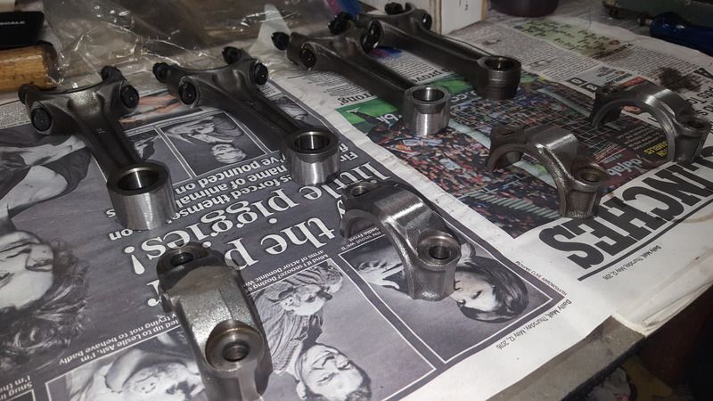
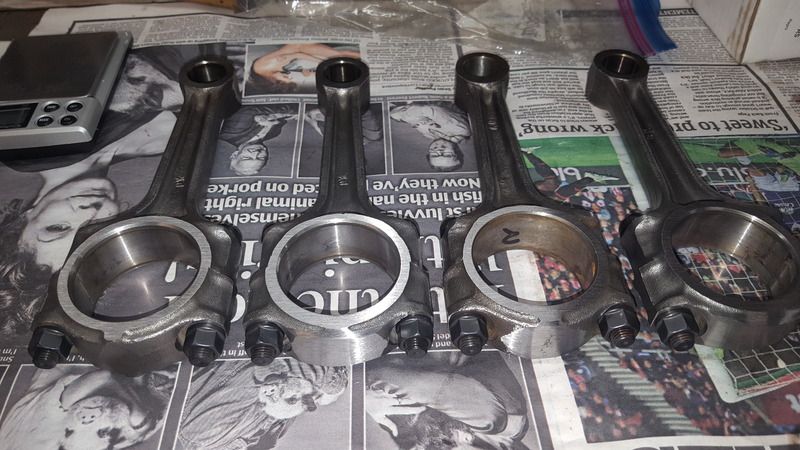
And with that I now have for balanced and slightly lightened rods.


20161008_163353.jpg


0 user(s) are reading this topic

0 members, 0 guests, 0 anonymous users