Jump to content


Photo
- - - - -

Bump Steer, And Identifying Mini Vs Metro Hubs Please ?


  • Please log in to reply
66 replies to this topic

#16 Spider

Spider

    Moved Into The Garage

  • Admin
  • PipPipPipPipPipPipPipPipPipPipPip
  • 13,934 posts
  • Location: NSW
  • Local Club: South Australian Moke Club

Posted 08 October 2015 - 05:55 PM


Spider. Which why did the wheel get effected in bump and drop on a standard set up?

Got some bottom balljoint spacers on the way for mine. Could be interesting.


I'll try to make some time this afternoon to dig that out of the Office PC and get it to you. It's only some loose 'sketches' I did on CAD after plotting where all the pick up point and joint centres are.


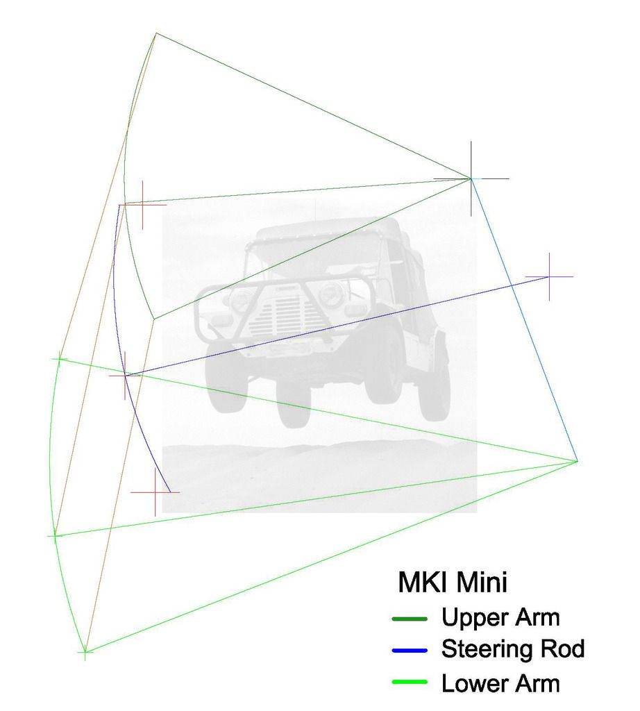
Please excuse the amateur nature of this 'sketch up' but it does serve to show the problem.


MKI%20Mini%20Bump%20Steer%20WM_zpsjjc98u


The Orange near vertical line to the left shows the KPI through the full movement.


More importantly, the Blue Line and Arc shows the sweep of the Steering Rod to the Pivot Point where the Steering Arm Connection is made. The Red Crosses show where this needs to be for zero Bump Steer.


I've now checked and the MKII Inner Rack is 1/2" longer between the Rod End Ball Joint Centres than the MKI



#17 Spider

Spider

    Moved Into The Garage

  • Admin
  • PipPipPipPipPipPipPipPipPipPipPip
  • 13,934 posts
  • Location: NSW
  • Local Club: South Australian Moke Club

Posted 08 October 2015 - 06:09 PM

MontpellierVanMan, I don't disagree that - on paper - the Car has Bump Steer, you have found similar to what I have found, though I've not drive a Mini with a full MKII Steering set up.


However, in driving the car, I don't notice it. The car doesn't seem to steer itself over the road as suspension angles change, even having different angles from one side to the other.


However, the effect is real and if set up wrong, becomes very noticeable and it doesn't take much at all to upset things.


Case in Point, I have driven a Car with a MKI Rack that was fitted with MKII arms and the effect is VERY noticeable and not pleasant. I also have similar plots to those above ^ with the MKII Steering Gear and also I did one with a MKI Rack and the MKII Arms.


To correct what I found, it was necessary to Move the complete Steering Rack Down 26.7 mm and shorten each side by 4.8 mm (for a MKI set up) to get the Rack Rod End Joint Centres in to the correct position. That was as far as I got, and one of the next things I was going to look at was to move the pick up point of the Arms as this would be easier to do that move the rack down, but it would still be necessary to shorten it.


#18 MontpellierVanMan

MontpellierVanMan

    Mini Mad

  • Noobies
  • PipPipPipPip
  • 102 posts
  • Location: Montpellier

Posted 08 October 2015 - 06:11 PM

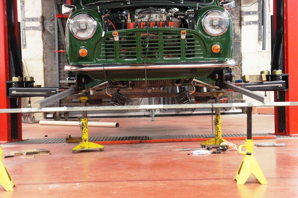
GEOMETRY%204_zpsdrsrknz3.jpg


The arms are off a bog-standard 1979 Van that I have owned since 1981. This makes them MkII n'est-ce-pas ?


They have a 33mm off-set as per the drawings helpfully provided by our Moke friend, and the references cast into them are BTA897S and BTA 896S, which appears to be MkII.


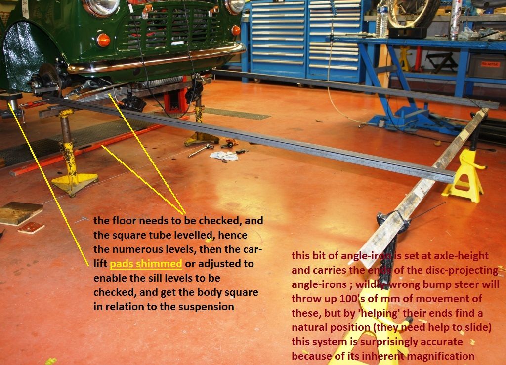
GEOMETRY%205_zpsjhvqsrns.jpg


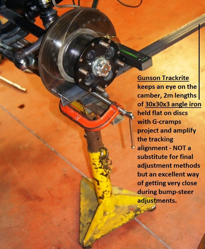
1. Why did I do all of the above ? Because the bump-steer was awful.


GEOMETRY%206_zps7eyvnarz.jpg


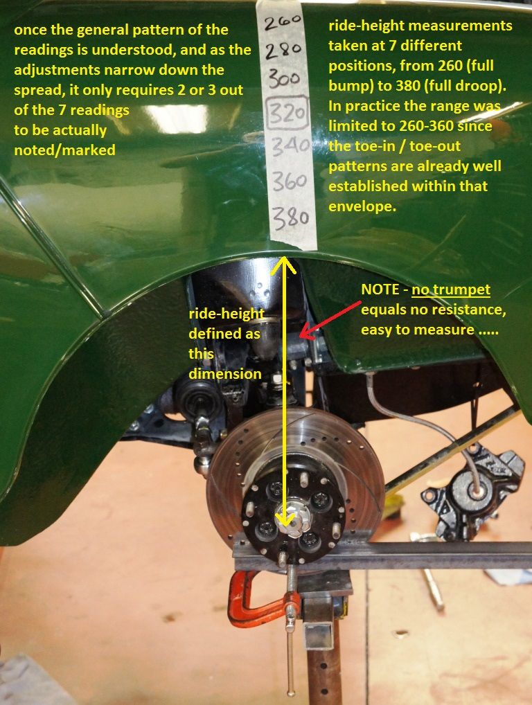
2. When did I do this work ? Recently, because the bump-steer was awful.


GEOMETRY%207_zpszvj61yka.jpg


3. And what's it like now ? Camber, Caster, Bump-Steer, all spot-on, and good Camber Curve to boot.


GEOMETRY%208_zpspqzngol2.jpg


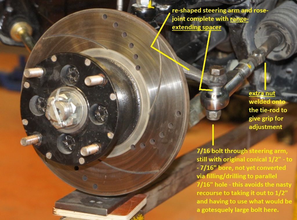
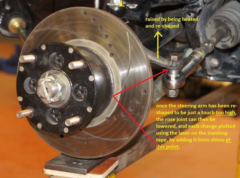
The modifications to the steering arms have not "made things worse", they have put the track-rods in a position where the bump-steer is perfect, the twist put on the end optimises the rose-joint range, and enables the use of McGill's boots.


GEOMETRY%209_zpsf6fd5jgk.jpg


The Ackermann offset is unchanged, it being interesting to note that - insofar as I am aware - BLMC didn't judge the longer Van/Estate as needing different arms to cope with what would be a modified Ackermann requirement.


GEOMETRY%2012_zpswih41cal.jpg


Input from someone who has plotted - accurately - the bump-steer through droop to bump on a standard Mini would be an invaluable contribution.


GEOMETRY%2013_zpsmiwnt9gz.jpg


GEOMETRY%2026_zpsiug6a30l.jpg


Edited by MontpellierVanMan, 11 October 2015 - 08:27 AM.


#19 Spider

Spider

    Moved Into The Garage

  • Admin
  • PipPipPipPipPipPipPipPipPipPipPip
  • 13,934 posts
  • Location: NSW
  • Local Club: South Australian Moke Club

Posted 08 October 2015 - 06:25 PM

MontpellierVanMan, I've just had a look through your post 4 up.


Very cleaver method of measuring (we did our wheel alignments in a similar way, but I now have made a lazer tool that is so much faster to set up).


Apologies on my comment 'may make things worse' it was not intended to offend and I hope you didn't take it that way.


I do like your new rod end set up and that the centre is now adjustable in the vertical too, that makes sence.


If I recall, the Van wheelbase was only 4" longer than the Saloon and being a Commercial Vehicle, I think they felt they could get away with the Ackermann error, the cars weren't that 'precision' in any case.


Thinking back now when I did my study (which was only a couple of months ago!) I did come to the realisation that the MKII set up was much worse for Bump Steer than the MKI. I'm in Australia and right to the end of production in 1978 (for the Mini), we retained MKI Steering Geometry. I've not yet had the 'privilege' of driving a Mini with MKII Steering Gear.


#20 Spider

Spider

    Moved Into The Garage

  • Admin
  • PipPipPipPipPipPipPipPipPipPipPip
  • 13,934 posts
  • Location: NSW
  • Local Club: South Australian Moke Club

Posted 08 October 2015 - 07:41 PM

OK, now I've thought about your mods and considered it on my plots.


Yes, moving the Steering Arm Pivot Point up as you have done on a MKII will remove the Bump Steer, I see what you've done and how it works.


But,


Why does a MKI set up drive OK, when it should not?


#21 mini13

mini13

    Up Into Fourth

  • Members
  • PipPipPipPipPipPipPipPipPip
  • 3,805 posts

Posted 08 October 2015 - 08:36 PM

Well, this is VERY interesting stuff!


well done for doing all the measurments, ive had a read through, and havent actually seen any bum steer measurments that I'd be that concerned about, can you point out the worst measurment as maybe i glossed over it,


But thinking in terms  of tow out, what do we notmally run? 1/16" across the diameter of the tyre?  if we extrapolate that out to the end of your measurment arms, thats somthing in the order of 1-2" from parralel??


I seem to remember mention of the lotus sunbeam having atroucios bump steer, somthing like 5/8" variation in toe across the diameter of the tyre from full bump to full droop.


Also, bump steer can almost help in certain instances, for example, if you get a bit of toe in under bump, this can negotiate to toe out that happens due to flex under braking.... might get a bit squirrelly under throttle though,


Also its worth considering it  in terms of " roll steer" a bit of bum toe in can add posotive steer in roll.


#22 nicklouse

nicklouse

    Moved Into The Garage

  • TMF+ Member
  • PipPipPipPipPipPipPipPipPipPipPip
  • 17,945 posts
  • Location: Not Yorkshire
  • Local Club: Anonyme Miniholiker

Posted 08 October 2015 - 08:59 PM

Al I can say is hats of to you for the work done.

And has given me food for thought.

And we have gone slightly off topic.

As to looking at a standard set up Mr Moke has most likely done the most. I have looked at the top bit of the travel and not much of it at all. And had come to similar conclusions to how the bump steer changed. I stopped with 1 degree of wheel angle change over the suspension travel.

Moke if I read your info right bump gives more toe in and drop turns it to toe out.

When driving in a straight like this change does not really make any difference to the handling and still happens to modern cars.

Now let's look at a corner. What happened when you turn the steering wheel car not moving. The caster adds neg camber. Which is good. Now let's look at what actually happens when in motion. The car rolls. What does this do to the camber? It takes some off. Which is not so good. But as the car rolls the suspension also get compressed which adds neg camber. And in the corner it also adds a little more steering angle on the outer wheel and takes some off on the inner wheel.

You also must consider the tyres. They can hide a multitude of errors or show them up.

And I have it all to do again when I drop the lower outer ball joint. Better get that laser bought.

#23 MontpellierVanMan

MontpellierVanMan

    Mini Mad

  • Noobies
  • PipPipPipPip
  • 102 posts
  • Location: Montpellier

Posted 08 October 2015 - 09:22 PM

None that you'd be concerned about ? Run through this with me please.


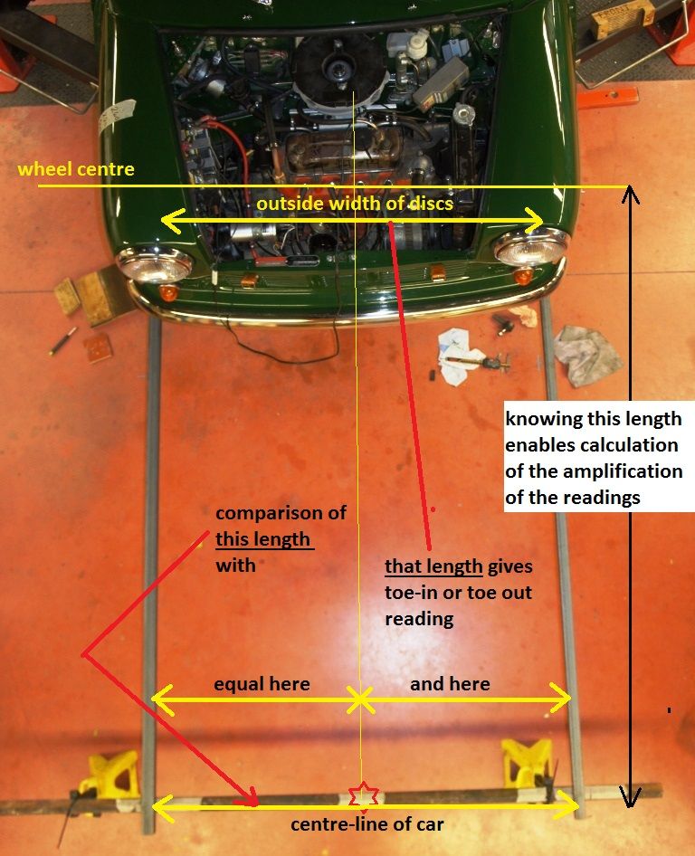
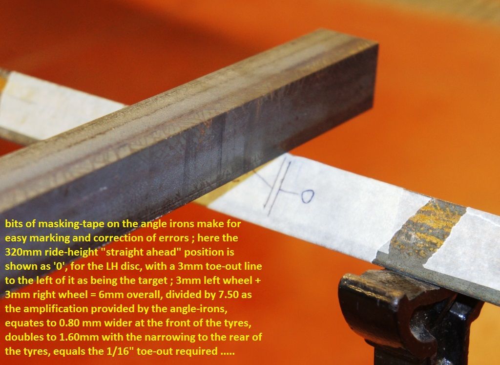
The 1/16" quoted for toe-out is measured on the tread of the tyre, and it translates to 1/64 "out" at the front of each tyre, relative to the centre-line of the car, and 1/64 "in" at the rear of each tyre.


Those 4 x 1/64" shifts add up to a 1/16" difference between the front and rear of the front tyres, which is the quoted figure.


The front wheel on my car is about 48cm diameter, so the 1/64" I'm looking for is the smallest side of a triangle that measures 240mm by 240mm by 0.4mm.


My angle irons actually measure 1m93 from wheel centre to end, so the magnification is 193/24 or almost exactly 8-fold.


Thus I'm looking for 8 x 0.4mm toe out on each front of the tyre, which is 3.20mm, or about 6mm overall measured on the other angle iron that lies at right angles to the main pair.


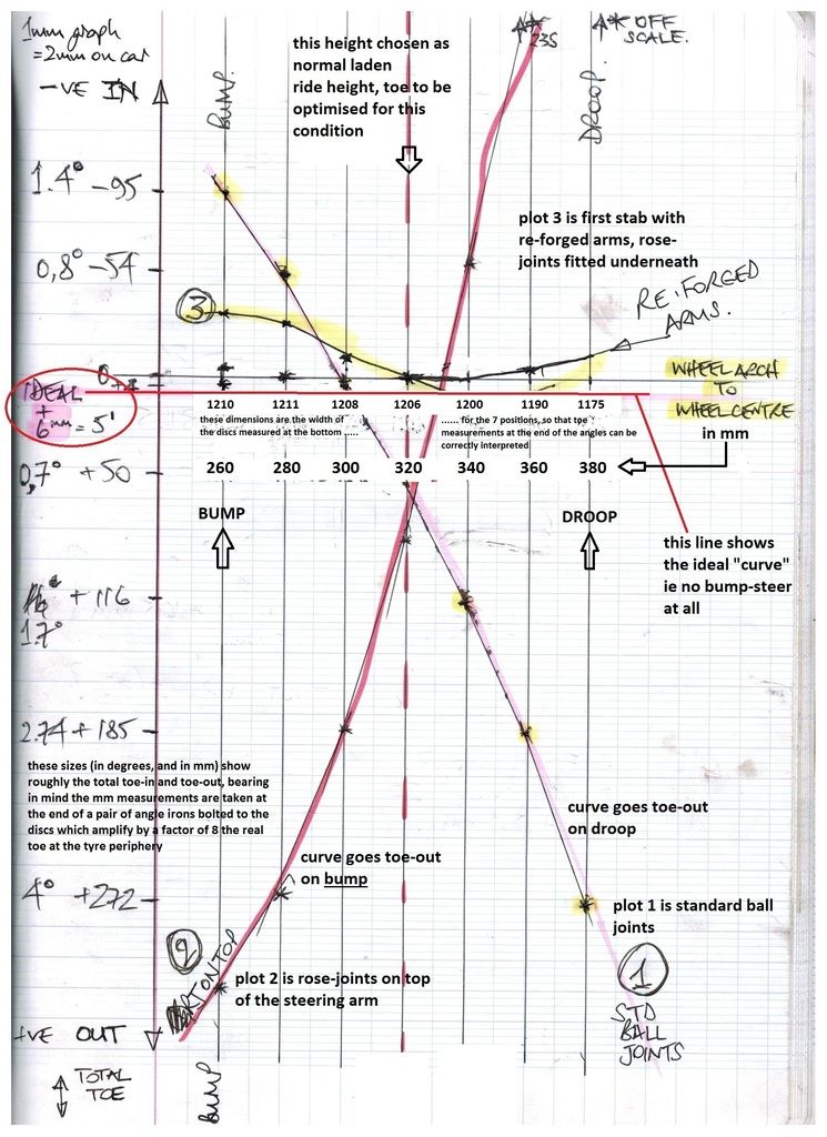
The initial readings I got with the original ball-joints and original Van arms gave me 272mm of toe-out at full droop, and 95mm toe-in at full bump ! That's a 367mm difference. Or 6° change, which is sixty (60 !) times the required setting.


When I fitted rose joints initially, I tried them on the top of the steering arm to try "going the other way". Boy did it go the other way ...............


I got 300mm of toe-out at full bump, and 235mm of toe-in at full droop. The curve had flipped. 535mm of difference ! That's about eighty (80 !) times the required setting.


So I think these mods were necessary and worth doing. But I still don't know WHY they needed doing !


PS : In an extreme case like this, tan-1 equals sin-1 (can't do powers on here sorry), same result, of 0.4mm/240mm or 0.00166667 gives just under 6' (minutes) of arc - each wheel needs to be cocked 6/60° out of true to get the right toe-in.


So " accuracy to within 1° " (which is 60' of arc) is still the equivalent of 10x our required toe-out measurement, which rather makes setting the latter at all pretty irrelevant ?


Edited by MontpellierVanMan, 08 October 2015 - 09:28 PM.


#24 mini13

mini13

    Up Into Fourth

  • Members
  • PipPipPipPipPipPipPipPipPip
  • 3,805 posts

Posted 08 October 2015 - 10:27 PM

Ohhhhh!


Sorry, totally misread this, I was looking at the tape measurments  trying to see somthing that was out of the ordinary thinking thats a fewmm on the end of a 2m bar....


are the bottom arms rosejointed too? also are the rubber cones disconnected?  loading of the suspension could distort the measurments a bit,


Ive wondered before if the rack location could be slightly different on Mk1 shells, and when the later comonents get put in it all gets squiffy....


Also we need to consider tracking and toe as an "average" its never going to be exact, and certainly not over the full suspension travel. on  mini what suspension travel are we really looking at? 1 1/2"? probably less on a track car,


I really need to re read this when I'm properly awake.


in terms of Akerman angle, is it getting better or worse due to the longer  wheel base (worse I think??), I know some lotuses and race cars run redused ackerman angles for better handling at speed, IIRC ackerman is all very good driving tround a carpark slowly for tyre wear, but once you start moving and getting into slip angles it starts to go out of the window.


in terms of reducing stiction between your arms and the parralell bar, how about suspending the arms slightly (a few mm), if the spending string is long enough it shouldnt affect accuracy.


#25 Spider

Spider

    Moved Into The Garage

  • Admin
  • PipPipPipPipPipPipPipPipPipPipPip
  • 13,934 posts
  • Location: NSW
  • Local Club: South Australian Moke Club

Posted 09 October 2015 - 02:53 AM

In general with most cars, usually, by having Ackermann in the set up, it is this which introduces Bump Steer in to most factory set ups, but mearly removing that, is all but goes away, however then lower speed, sharper turns become a real chore,, scrub, scrub scrub,,,,


Moke if I read your info right bump gives more toe in and drop turns it to toe out.

When driving in a straight like this change does not really make any difference to the handling and still happens to modern cars.


Yes, it goes Toe Out on Droop and it really goes Toe IN big time on Compression.


I'll disagree in part with your second line here. With the MKI Steering set up, yes, Bump Steer - on paper - does occur, and on compression, in a pretty big way, yet, in driving, straight line, corners, where ever, it's not noticable.


However, there is some considerable sensitivity with the set up, as on the same car, I've had MKII Arms with the MKI Rack, re-set the Toe and the difference in driving is chalk and cheese, it really is noticeable and damn awful.


I found this an CAD too and while there is similar changes (Bump Steer) with this set up that can be seen there, it's not miles different to the full MKI set up, which isn't noticeable.


It does seem Mr. MontpellierVanMan has found by measuring on-car pretty much what I found working with CAD.


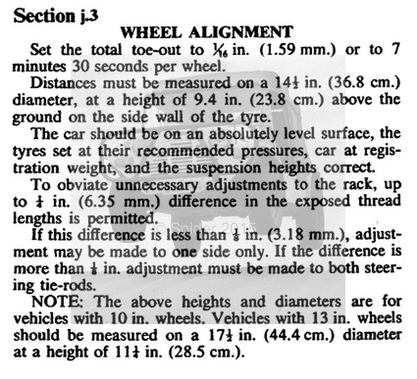
<EDIT: As mentioned elsewhere in this thread, the stock alignment settings include a 1/16" Toe OUT Figure for the Front Wheels, this is the factory Description as to where it's measured;-


ToeAdjustInfo_zpsoqc6du8r.jpg


>


Edited by Moke Spider, 09 October 2015 - 05:25 AM.


#26 nicklouse

nicklouse

    Moved Into The Garage

  • TMF+ Member
  • PipPipPipPipPipPipPipPipPipPipPip
  • 17,945 posts
  • Location: Not Yorkshire
  • Local Club: Anonyme Miniholiker

Posted 09 October 2015 - 06:49 AM

Something that has not been mentioned, or asked, is how the car drives now?

#27 MontpellierVanMan

MontpellierVanMan

    Mini Mad

  • Noobies
  • PipPipPipPip
  • 102 posts
  • Location: Montpellier

Posted 09 October 2015 - 02:07 PM

How does it drive ? I'll tell you when I've got my licence back ............. small issue of Grand Excès de Vitesse - that's SPEEDING to you - on a scooter, ahem.


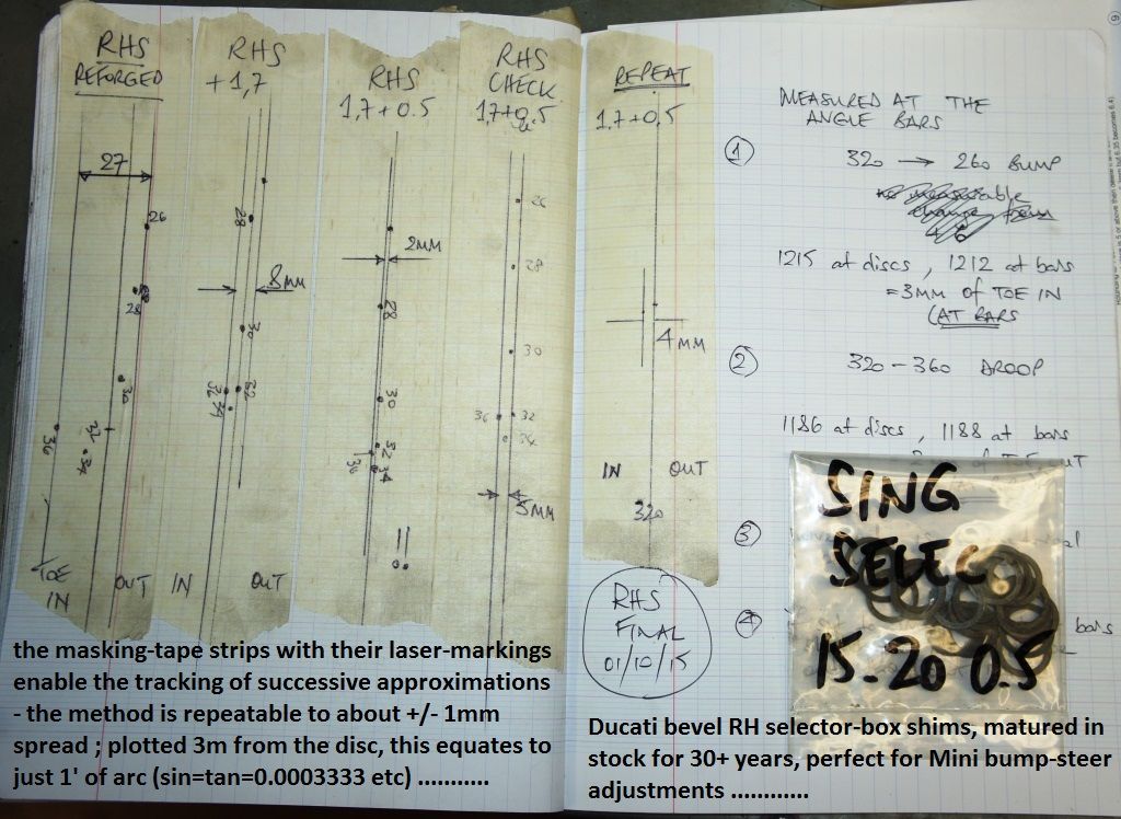
Here are the first curves which might help others with the method ; not pretending ANY deep understanding of Minis in any of this, but have owned the car almost from new and spent 40 years in maths, engineering, and racing, so do have some clue.


"Noobie" does not necessarily imply f-wit !


Attached File  Bump Steer Plots 001.jpg   54.56K   42 downloads


I've ended up with something that is very close to the ideal red-line shown on the plots.


Edited by MontpellierVanMan, 11 October 2015 - 09:02 AM.


#28 nicklouse

nicklouse

    Moved Into The Garage

  • TMF+ Member
  • PipPipPipPipPipPipPipPipPipPipPip
  • 17,945 posts
  • Location: Not Yorkshire
  • Local Club: Anonyme Miniholiker

Posted 09 October 2015 - 10:29 PM

The resolution is a bit low on that so having fun trying to guess some of the words,

But something that I don't seem to have picked up on is the measurement between the hub mounting face and the, let's say as you have twisted it, centre of the lower circle of the new bolt hole in the hub.

As I will gave a play as I still have this.
Attached File  image.jpeg   46.13K   11 downloads

#29 Spider

Spider

    Moved Into The Garage

  • Admin
  • PipPipPipPipPipPipPipPipPipPipPip
  • 13,934 posts
  • Location: NSW
  • Local Club: South Australian Moke Club

Posted 10 October 2015 - 07:35 PM

Have you also checked the Bump Steer since altering it, through a few steering angles?


Edited by Moke Spider, 10 October 2015 - 07:35 PM.


#30 MontpellierVanMan

MontpellierVanMan

    Mini Mad

  • Noobies
  • PipPipPipPip
  • 102 posts
  • Location: Montpellier

Posted 11 October 2015 - 08:07 AM

Maybe that's a better copy ? I've added PhotoBucket links to all the other shots from the previous posts whilst I'm at it ............


Bump%20Steer%20Plots%20001_zpsqei8xhel.j


No, Moke, I haven't "checked" bump-steer at any other steering angles since I have no idea whatsoever how to interpret the results.


I haven't even found any credible measurements of what the BS looks like on a standard car in the straight-ahead position .............


Rory


Edited by MontpellierVanMan, 11 October 2015 - 09:01 AM.


0 user(s) are reading this topic

0 members, 0 guests, 0 anonymous users