Jump to content


Photo
- - - - -

Mcmini Micra Conversion


  • Please log in to reply
308 replies to this topic

#286 micraminiman

micraminiman

    Mini Mad

  • Members
  • PipPipPipPip
  • 151 posts
  • Location: Scottish Highlands

Posted 03 August 2017 - 08:41 AM

Your clearances are just fine, no problems there. The engine doesn't move much at all.

 I did add a head steady shock absorber from a Honda to the offside at the top. Its totally cut down on any movement at all when going on and off the throttle.

Done nearly 2000 miles in mine now since finishing the conversion and its amazing, your gonna love it!

Attached Files


#287 Northernpower

Northernpower

    Mr. 7-Port

  • Members
  • PipPipPipPipPipPipPipPipPip
  • 2,409 posts
  • Name: Graham
  • Location: North Yorkshire (God's County)
  • Local Club: Its out there somewhere

Posted 03 August 2017 - 08:47 AM

Your clearances are just fine, no problems there. The engine doesn't move much at all.

 I did add a head steady shock absorber from a Honda to the offside at the top. Its totally cut down on any movement at all when going on and off the throttle.

Done nearly 2000 miles in mine now since finishing the conversion and its amazing, your gonna love it!

Liking the look of the little shock absorber, what's it off?


#288 micraminiman

micraminiman

    Mini Mad

  • Members
  • PipPipPipPip
  • 151 posts
  • Location: Scottish Highlands

Posted 03 August 2017 - 10:50 AM

This is what I bought. Had to make a new mount for the bulkhead, and modified a mount that came with it for the engine.

http://www.ebay.co.u...872.m2749.l2649


#289 McMini 22

McMini 22

    Mini Mad

  • Members
  • PipPipPipPip
  • 289 posts
  • Location: East lothian

Posted 03 August 2017 - 05:53 PM

I have something similar. I'll get a photo up tomorrow. Thanks to photobucket I can't post photos from my phone!
I am now worrying about my inlet manifold cracking under the weight of the throttle body. I'll either strengthen it or fit the jenvey 52mm throttle body.
Haven't been doing too much on the mini for a bit. Too many other things on!

#290 micraminiman

micraminiman

    Mini Mad

  • Members
  • PipPipPipPip
  • 151 posts
  • Location: Scottish Highlands

Posted 04 August 2017 - 08:25 AM

Been thinking about bracing the inlet on mine too. Know a lad whose Fusion inlet cracked. He braced his one up and had no issues since.


#291 McMini 22

McMini 22

    Mini Mad

  • Members
  • PipPipPipPip
  • 289 posts
  • Location: East lothian

Posted 04 August 2017 - 01:08 PM

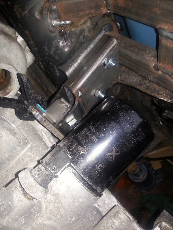
This is what I did for a rear engine mount on the drivers side (prior to painting).


35518679724_ee44c40afe_b.jpgRear right engine mount by Ewan McLean, on Flickr


It has a homemade polyurethane (cast) bush in it to absorb a bit of the shock.  It is adjustable in every direction and bolts to the engine with three conveniently placed M10 holes (thanks Nissan!).


Re Plenum cracking -

I'm sure it was someone on here who's FF one cracked.  There is some weight in the Nissan throttle body which will not help.  My plenum is a bit longer than the FF one so after seeing the photos of the cracked one it got me thinking.  I need to ask a few questions about my 52mm throttle body over on the Micra forum before I make a decision.  I am worried that this setup will suck more air than the Micra ECU can cope with.

In the meantime I plan to just get it running on the Micra throttle body.


Should get a bit done soon as I have the entire weekend to myself.  I do however still have bit of tidying up to do.  No idea who made all this mess!!! :rolleyes:


#292 fuzzy-hair-man

fuzzy-hair-man

    Mini Mad

  • Members
  • PipPipPipPip
  • 181 posts
  • Location: Armidale NSW
  • Local Club: Minis in the Gong

Posted 05 August 2017 - 02:01 AM

I have a ga15 throttle body on mine at 50mm (45mm for cg13de) we worked out the maf sensor is the same so there wasn't even anything to change via nistune. I can't fault it, I doubt there'd be any problems for yours. I think the Sr20 60mm? one can get too big though.

#293 McMini 22

McMini 22

    Mini Mad

  • Members
  • PipPipPipPip
  • 289 posts
  • Location: East lothian

Posted 07 August 2017 - 12:37 PM

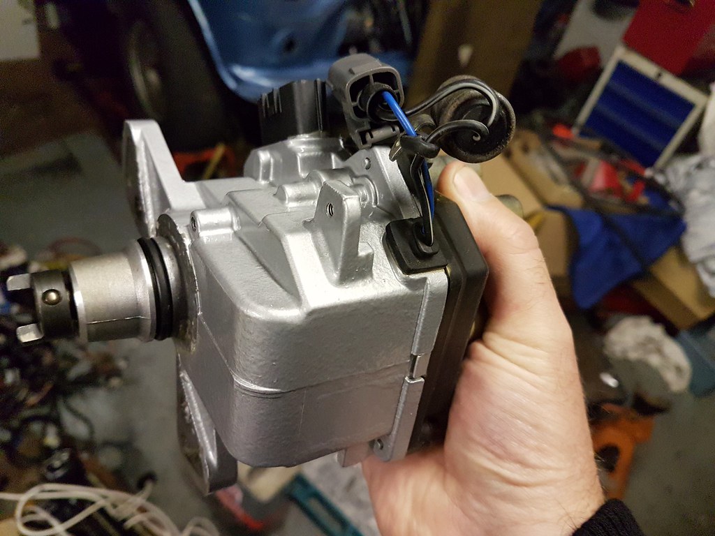
I cleaned up the distributor and fitted it on.  It looked terrible against the rest of the engine so it was time to get painting.


A quick primer then a coat of 2K gloss silver (saves on the lacquer!)  and it looks lovely.


36254054732_2f2e773789_b.jpgDistributor painted by Ewan McLean, on Flickr


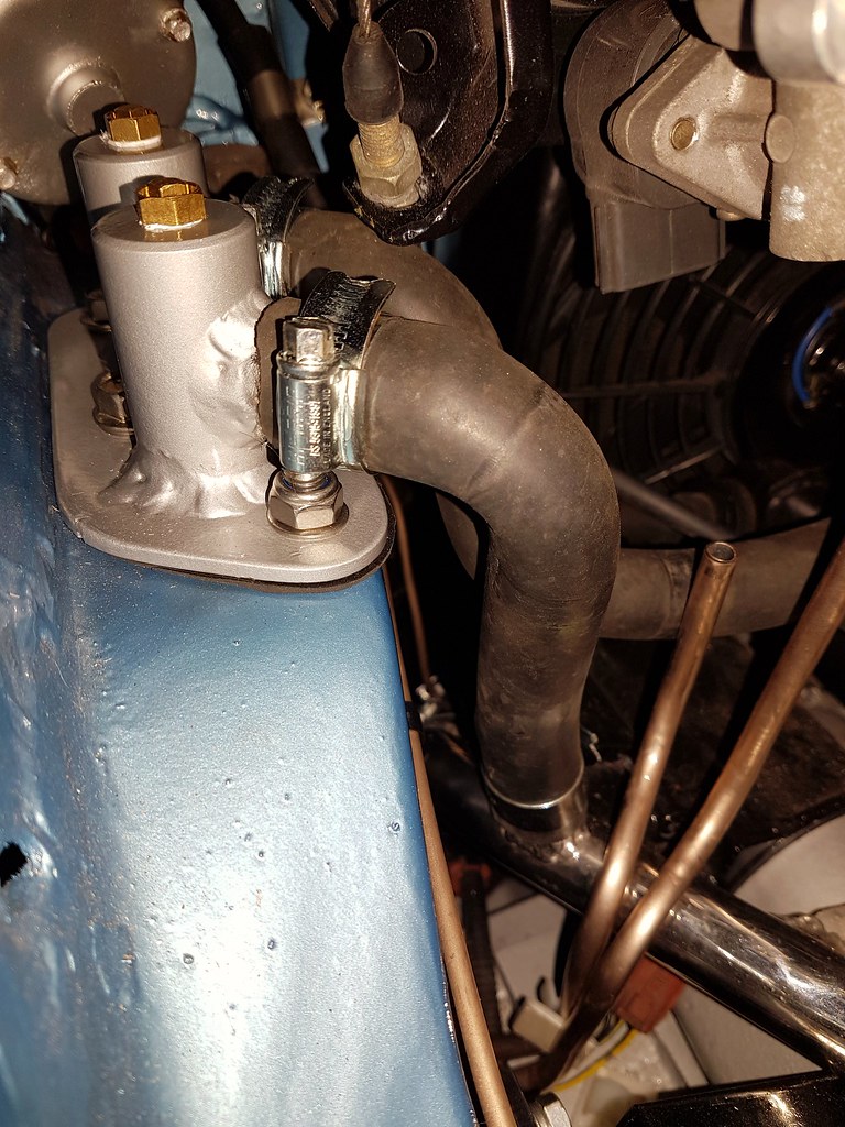
Also painted the master cylinder and the bulkhead fitting for the heater hoses.


Almost ready to start wiring!


#294 McMini 22

McMini 22

    Mini Mad

  • Members
  • PipPipPipPip
  • 289 posts
  • Location: East lothian

Posted 17 August 2017 - 12:32 PM

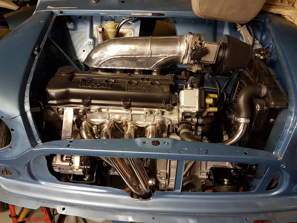
Well that's as much as I can do to the engine at the moment.  I can't put the wiring off any longer.

I'm happy with how this looks so far.


35808075213_3d875efefb_b.jpgReady for wiring by Ewan McLean, on Flickr


There is however a clash between the throttle cable and the heater bulkhead fitting.  No big deal, I'll modify the throttle cable bracket (later!)

35808090123_95df596e35_b.jpgAccelerator cable foul by Ewan McLean, on Flickr


Any tips on where to start with the wiring greatly appreciated!!  So far I placed the fuse board roughly where it wants to be (drivers side dash) and I have started placing the engine wiring where it should be.  Engine wiring needs modifed to fit as the throttle body is in a completely different position.


#295 thelegg

thelegg

    Super Mini Mad

  • Members
  • PipPipPipPipPipPip
  • 601 posts
  • Location: Forton

Posted 18 August 2017 - 05:37 AM

Just start plugging everything in and try to run wires where you want them shortening or lengthening them as you go :)

#296 micraminiman

micraminiman

    Mini Mad

  • Members
  • PipPipPipPip
  • 151 posts
  • Location: Scottish Highlands

Posted 18 August 2017 - 08:31 AM

Mount the fusebox and ECU in location first. Just do the loom in small stages. The throttlebody loom needs peeled back, but the wires will reach the new location before taping it back up. I didnt drill any new holes in the bulkhead. I also used the Micra bulkhead grommets. Got loads of pics of mine on the Facebook group, just do a group search for "wiring".


#297 McMini 22

McMini 22

    Mini Mad

  • Members
  • PipPipPipPip
  • 289 posts
  • Location: East lothian

Posted 18 August 2017 - 12:47 PM

Cheers. I bought some solder sleeves and a land rover fuse box. Get it running before cutting.

I hate wiring!

#298 Northernpower

Northernpower

    Mr. 7-Port

  • Members
  • PipPipPipPipPipPipPipPipPip
  • 2,409 posts
  • Name: Graham
  • Location: North Yorkshire (God's County)
  • Local Club: Its out there somewhere

Posted 18 August 2017 - 01:16 PM

Cheers. I bought some solder sleeves and a land rover fuse box. Get it running before cutting.

I hate wiring!

Keith Calver wrote this article, makes for interesting reading.


'To solder or not to solder, that is the question'


Despite having spent something in the order of 26 years delving into all things automotive and some 24 of those concentrating a great deal on the Mini, I have never assumed I know it all. In fact I'm very much one of those to support the 'you never stop learning' theory. My latest endeavours to get out racing again have caused me to look at all things connected (sorry - pun) with racecar preparation - the wiring loom being one such item.


I decided to canvas everybody I knew that was involved with electronics and electrics to any degree to see what the latest state of play was concerning fixing terminals to cables. 'To solder or not to solder, that is the question'. All my previous racecars (last one built about 14 years ago) had all the terminals carefully soldered on. It used to take me ages; taking a remarkably long time to become proficient at it - largely because of the 'not too hot' soldering iron I'd purchased to do the job. One of my electronics specialist friends pointed out I'd probably get just as good a result by farting on the joint as I would with the iron I'd bought. Very kind I'm sure. The investment of a small fortune in a proper soldering iron soon had me sticking terminals to cables in a seriously rapid fashion. The count was coming down about 60% in favour of simply crimping the terminals on. The other 40% interestingly was made up of mostly 'older' (more learned?) electrical/electronic types. Considering the arguments for and against proffered by all and sundry, the opinions that really swung it for me (and my enquiring mind) went down to mainly two folk - one who designs/manufacturers and trouble-shoots electronic control systems in the manufacturing and test equipment industry, the other works for a prominent formula one team. The main reason for my decision about this was the fact the fruits of both their labours are used in the same hostile environment that my racecar will see - prolific vibration.


The result is the terminals will simply be crimped on to their respective cables. Why? Apparently soldering any electrical joint will make a good watertight connection, BUT will make it somewhat brittle. In hostile environments that see a lot of vibration this brittleness will eventually result in the cable/joint fracturing. Not good since on a race-car this means no electrical connection varying in severity from a malfunctioning brake light to an engine that stops dead as the coil wire breaks off… Not funny when your at the sharp end of thirty or so racing Minis fighting furiously for the lead into the first corner at the start of a race! Yes, this happened to me at Snetterton in my Miglia many moons ago. Frightening. Fortunately everybody missed me as I rolled slowly off the circuit. Thanks guys. And I thought it was my crap soldering capability.


A crimped joint, on the other hand, retains sufficient flexibility to all but eliminate this occurrence. The trick is to use proper, quality crimping tools for the various terminal types available. Not a problem for me since I'm a firm believer in investing in quality tools and have accumulated all the relevant crimping equipment over the years. And the use of decent quality terminals of course. I buy all my stuff from a company called 'Vehicle Wiring Products' (0115 9305454) who are always helpful and prompt with supply. OK if you're in the UK I know - but I'm sure you foreign brethren are able to sort through a local or automotive directory to source some place suitable for you.


Where soldered joints are a must, this vibration fracture problem can be eased to some extent by the use of RTV silicone. A dab of this on the joint helps to absorb some of the vibration, consequently prolonging the life of the soldered joint. My formula one friend informs me this is how they treat the printed circuit boards in the myriad of ECUs used on an F1 car. Interesting isn't it?

Original article: 
http://www.calverst....minal-fixation/


Edited by Deathrow, 21 August 2017 - 08:36 AM.
Added link to original article.


#299 McMini 22

McMini 22

    Mini Mad

  • Members
  • PipPipPipPip
  • 289 posts
  • Location: East lothian

Posted 18 August 2017 - 07:04 PM

Interesting stuff! My solder joints when joining 2 wires always ends up wicking along the wire. It ends up with about 40mm of solid joint and by the time you add heatshrink then all flexibility is gone.
I used these solder sleeves at work many years ago and that was for military work. The fact that the solder ring is very short and the heatshrink supports the joint makes me happier.
I'll try them when they arrive and report back.

#300 lawrence

lawrence

    One Carb Or Two?

  • Members
  • PipPipPipPipPipPipPip
  • 1,330 posts

Posted 18 August 2017 - 07:19 PM

How come you get 40mm of solid joint? I normally strip 1.5 cm off the wire, twist it around each other and then add a dab of flux and enough solder to make it shiny. makes about 8mm of solder on the joint. Flux makes soldering much easier but needs wiping off with a wet cloth or it degrades the joint. 


0 user(s) are reading this topic

0 members, 0 guests, 0 anonymous users