Jump to content


Photo
- - - - -

Speedometer Not Working

electrical

  • Please log in to reply
7 replies to this topic

#1 barnestom

barnestom

    Passed Test

  • Noobies
  • PipPip
  • 32 posts
  • Location: West Yorkshire

Posted 28 May 2016 - 02:12 PM

Hi Guys,


Trying to diagnose a problem with my speedo not working.


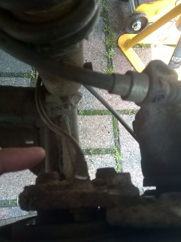
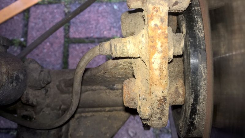
I have taken wheel off and had a look and think I have found the sensor


IMG-20160528-WA0001.jpg


WP_20160528_14_47_54_Pro.jpg


WP_20160528_14_48_14_Pro.jpg


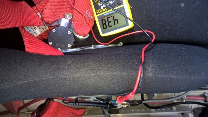
So I have stuck a multimeter on the two cables and am getting a constant read of 4.38/4.39.


Presuming I have got the multimeter set right and this is the correct cable. (it connects straight to a rally distance/speedo box thing) the cable reads 0 volts if the speedo is turned off and goes to the left back wheel.


When spinning the wheel by hand I see no difference in the voltage.


Am I correct in thinking this is enough to narrow it down to the sensor being bad? As the circuit wouldn't be showing anything if the cable was buggered?


#2 dklawson

dklawson

    Moved Into The Garage

  • TMF+ Member
  • PipPipPipPipPipPipPipPipPipPipPip
  • 10,923 posts
  • Name: Doug
  • Location: Durham, NC - USA
  • Local Club: none

Posted 29 May 2016 - 11:30 AM

I am not familiar with your sensor setup or speedometer so please consider the following information just general guidance.


There are two wire and three wire sensors.  Both will need to be focused on a metal surface that has "breaks" in it to allow the sensor to create on/off pulses.  Some of the sensors are the Hall Effect or reed switch types which require a magnet be in/on the rotating surface being monitored.


With three wire devices you will have two power wires (earth and 12V) supplying the sensor and an output wire.  Usually (but not always) the sensor wiring follows the common color code of blue for earth, brown for 12V in, black for the output signal.  An older color code scheme uses red, black, and white wires.  I haven't seen it used in years so it is unlikely that is what you have. 


Compounding the 3-wire sensors, there are NPN and PNP types that determine whether the sensor provides a path to earth or a 12V signal to the device it is connected to.  I only bring this point up because... the voltage measurements you are trying to make may be influenced by the type of sensor being measured.  It may also be that to test the sensor you need to disconnect its output wire from the speedometer so the gauge is not influencing your measurements.  A few pictures of the wire colors and a bit more information about which wires you are connecting to may help sort out what you are seeing in your measurements.  


Two wire sensors are speed sensitive.  They may not have an observable voltage pulse or wave until the rotational speed is above some threshold value.  You may need to spin the wheel faster to get a reading.


#3 Beatie

Beatie

    Passed Test

  • Noobies
  • PipPip
  • 34 posts
  • Location: Lingwood

Posted 29 May 2016 - 11:45 AM

The white or black output wire would normally dictate the sensor rest state either N/O or N/C .
Never knew minis had these on but never owned anything newer than a 78 😀

#4 barnestom

barnestom

    Passed Test

  • Noobies
  • PipPip
  • 32 posts
  • Location: West Yorkshire

Posted 02 June 2016 - 08:03 PM

The white or black output wire would normally dictate the sensor rest state either N/O or N/C .
Never knew minis had these on but never owned anything newer than a 78


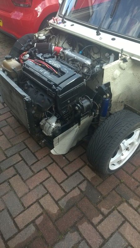
This is a 78 as well! Russet Brown 1000 Auto It's completely standard I swear  :lol:

WP_20150620_004.jpg


I am not familiar with your sensor setup or speedometer so please consider the following information just general guidance.


There are two wire and three wire sensors.  Both will need to be focused on a metal surface that has "breaks" in it to allow the sensor to create on/off pulses.  Some of the sensors are the Hall Effect or reed switch types which require a magnet be in/on the rotating surface being monitored.


With three wire devices you will have two power wires (earth and 12V) supplying the sensor and an output wire.  Usually (but not always) the sensor wiring follows the common color code of blue for earth, brown for 12V in, black for the output signal.  An older color code scheme uses red, black, and white wires.  I haven't seen it used in years so it is unlikely that is what you have. 


Compounding the 3-wire sensors, there are NPN and PNP types that determine whether the sensor provides a path to earth or a 12V signal to the device it is connected to.  I only bring this point up because... the voltage measurements you are trying to make may be influenced by the type of sensor being measured.  It may also be that to test the sensor you need to disconnect its output wire from the speedometer so the gauge is not influencing your measurements.  A few pictures of the wire colors and a bit more information about which wires you are connecting to may help sort out what you are seeing in your measurements.  


Two wire sensors are speed sensitive.  They may not have an observable voltage pulse or wave until the rotational speed is above some threshold value.  You may need to spin the wheel faster to get a reading.
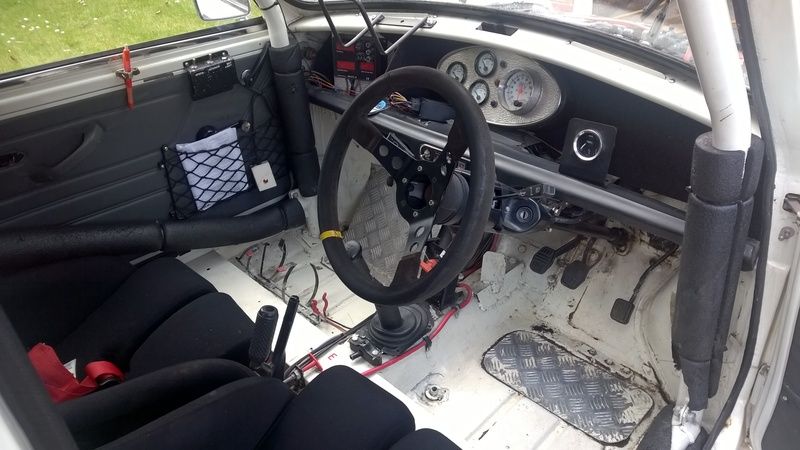
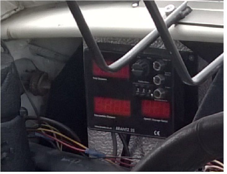
Well this has two wires brown and blue (its a rally car so any old wire could have been used haha)

It goes direct into the rally speedo thingamagig see below


WP_20150525_001.jpg

WP_20150525_001%20-%20Copy.jpg


#5 Beatie

Beatie

    Passed Test

  • Noobies
  • PipPip
  • 34 posts
  • Location: Lingwood

Posted 02 June 2016 - 10:35 PM

Do you know whether there are any joins in cable ?
You could well see resistance if you have a dodgy joint or damage to insulation somewhere along the line .
Maybe worth making a new joint nearer the sensor and testing with a new pair of cables ?

#6 Beatie

Beatie

    Passed Test

  • Noobies
  • PipPip
  • 34 posts
  • Location: Lingwood

Posted 02 June 2016 - 10:38 PM

And I take it that it's a wand change box 😂

#7 barnestom

barnestom

    Passed Test

  • Noobies
  • PipPip
  • 32 posts
  • Location: West Yorkshire

Posted 02 June 2016 - 11:16 PM

Do you know whether there are any joins in cable ?
You could well see resistance if you have a dodgy joint or damage to insulation somewhere along the line .
Maybe worth making a new joint nearer the sensor and testing with a new pair of cables ?

So there is a join in the cable I am attaching where it is (sensor side)

rest of cable looks undamaged to the sensor (you can see it 95% of the way to sensor.

When I power on the "speedo box" with the switch on the side the multimeter goes from 0 to the value shown in the picture above.


#8 Beatie

Beatie

    Passed Test

  • Noobies
  • PipPip
  • 34 posts
  • Location: Lingwood

Posted 04 June 2016 - 04:04 PM

Assuming that reading you see is vdc and does not change when you rotate wheel the try seeing if the resistance changes when rotating wheel ?
Set your meter to ohms and give it a spin
.
Failing all that have you searched the manufacturer out on the web ?
You might be able to gain some in depth knowledge from there ?
It might be that the output voltage is too low at 4.8 ?
Is it the sensor dragging it down or output in main box faulty ?
Sorry about the best I can think of


Also tagged with one or more of these keywords: electrical

0 user(s) are reading this topic

0 members, 0 guests, 0 anonymous users