Jump to content


Photo
- - - - -

1990 Brg - Miglia Mini Style Track Project


  • Please log in to reply
29 replies to this topic

#1 patto

patto

    Mini Mad

  • TMF+ Member
  • PipPipPipPip
  • 199 posts

Posted 08 January 2017 - 07:24 PM

Hi guys I thought I’d start a build thread for this even though I won’t actually be working on the car for some time yet. I’m currently looking to buy my first house and my mini is in storage so won’t able to start on it until that’s sorted. Once the house is sorted I’m hoping this will move along quite quickly, however at the moment I’ve got a few bits I’ve made I thought it was worth documenting hence the thread.


So the plan is to build a mild miglia style track car that's still road legal. Even though it will most likely be trailered to events I still want it road legal so I can do the odd Sunday drive and take it to meets and shows. I’m expecting to have to compromise in certain aspects to make it drivable on the roads however it will mainly be track based.


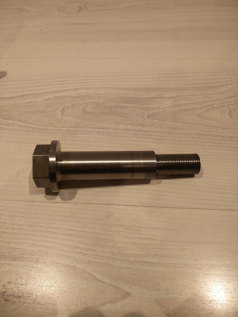
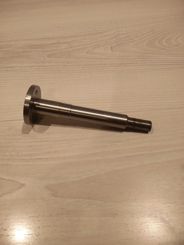
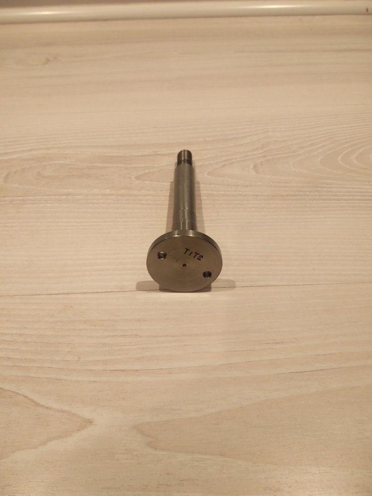
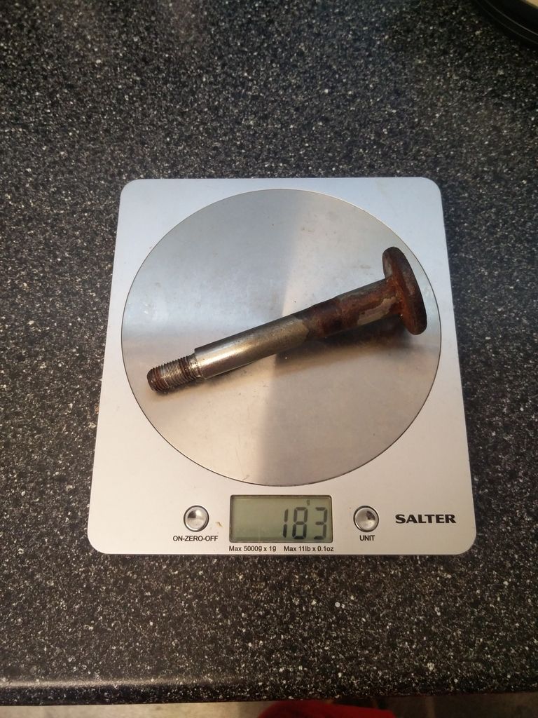
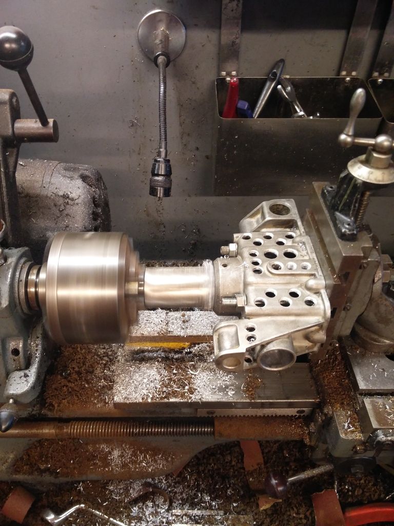
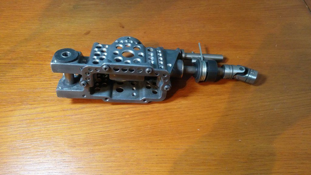
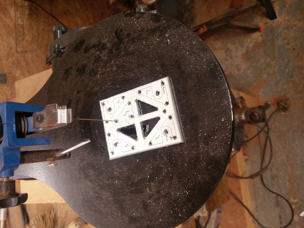
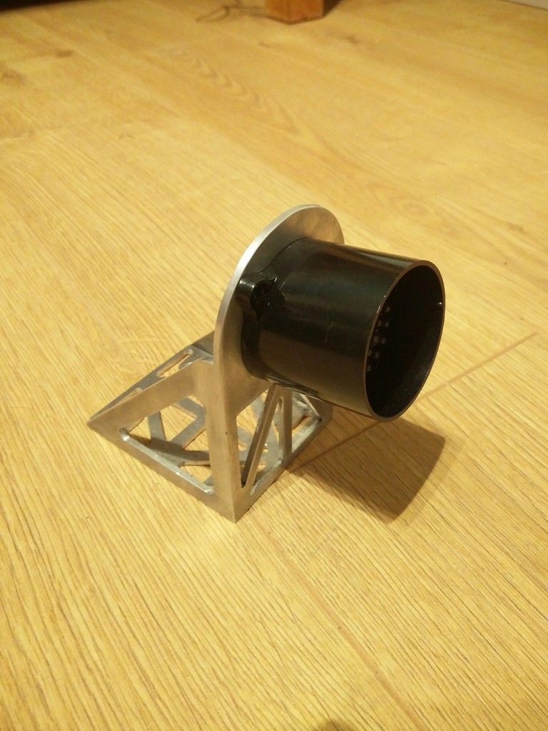
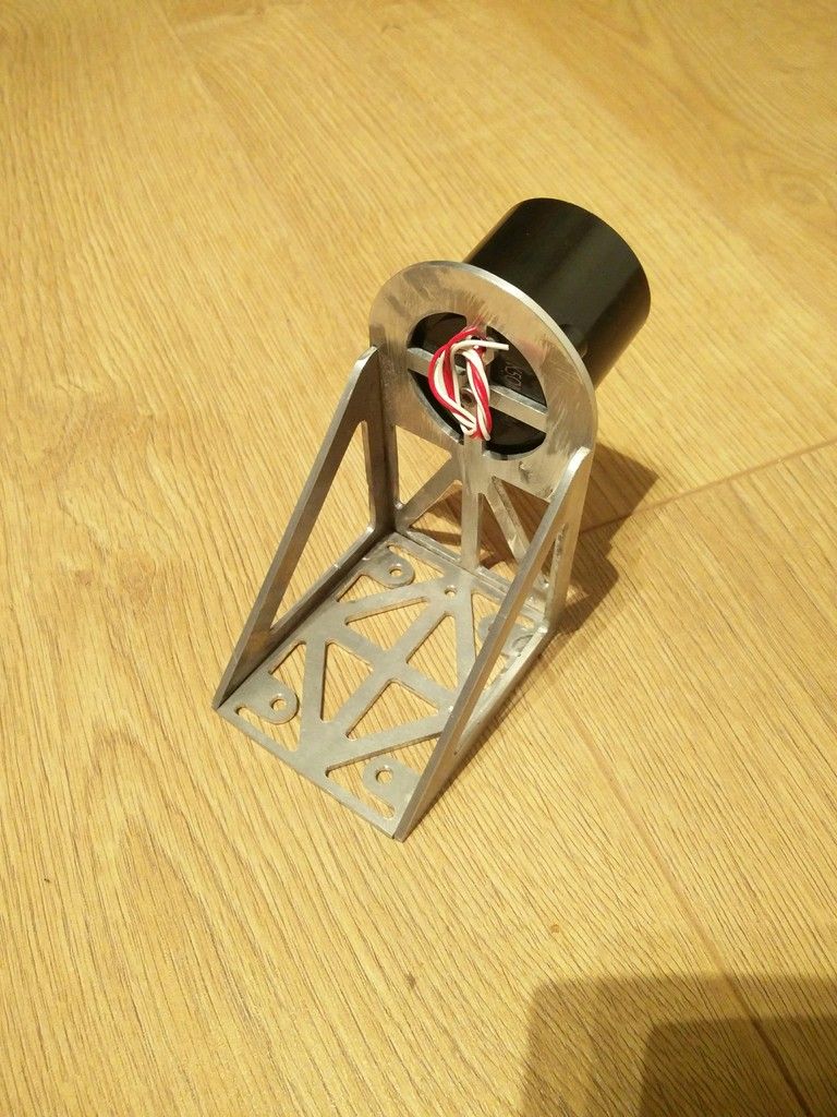
Styling wise I’ll be going for carbon miglia arches, roof, front end, and boot, 10” force racing split rims. Then totally stripped out with a full cage, bucket seats, harnesses and other than that everything very minimalist. I’m wanting to get it as light as possible but I’m going to try and not get carried away with it (this may have already happened). The whole plan with this project is to build something to the absolute best of my ability with no real restraints on cost or time (within reason), and if I can make a component as good or better than buying something I’m going to make it.


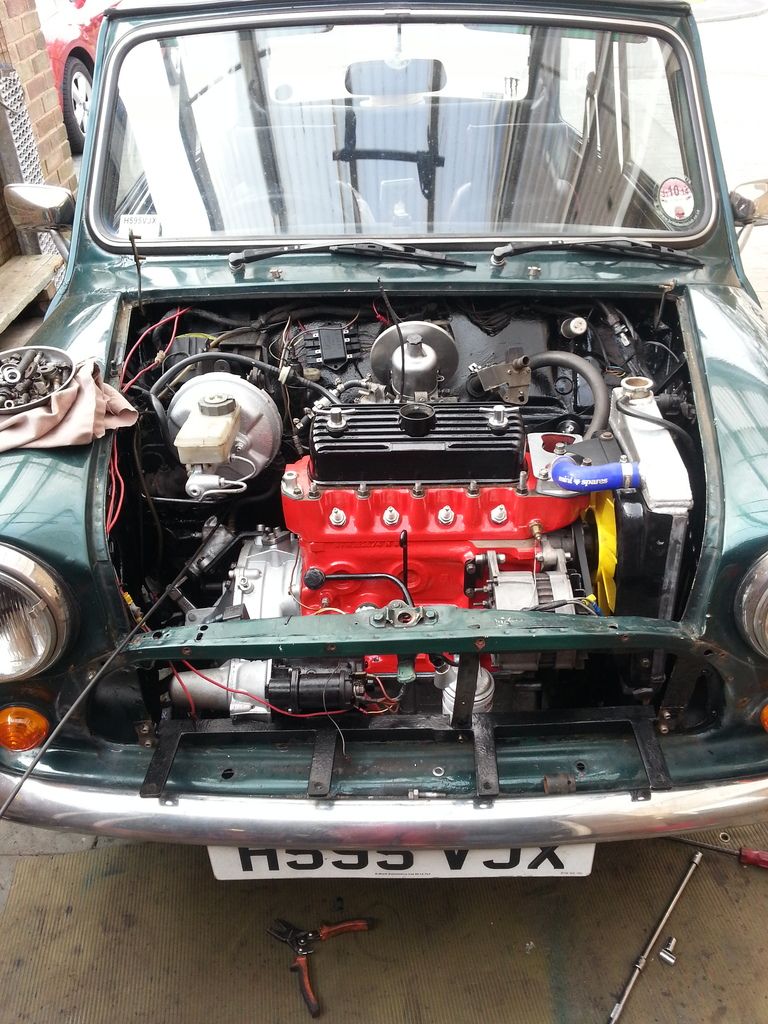
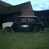
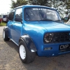
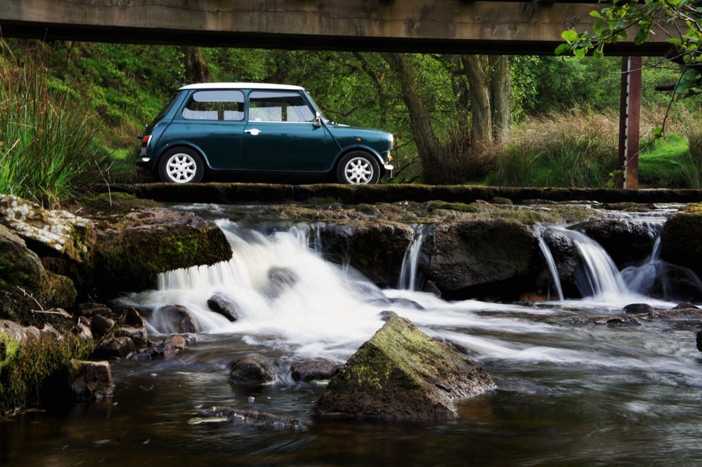
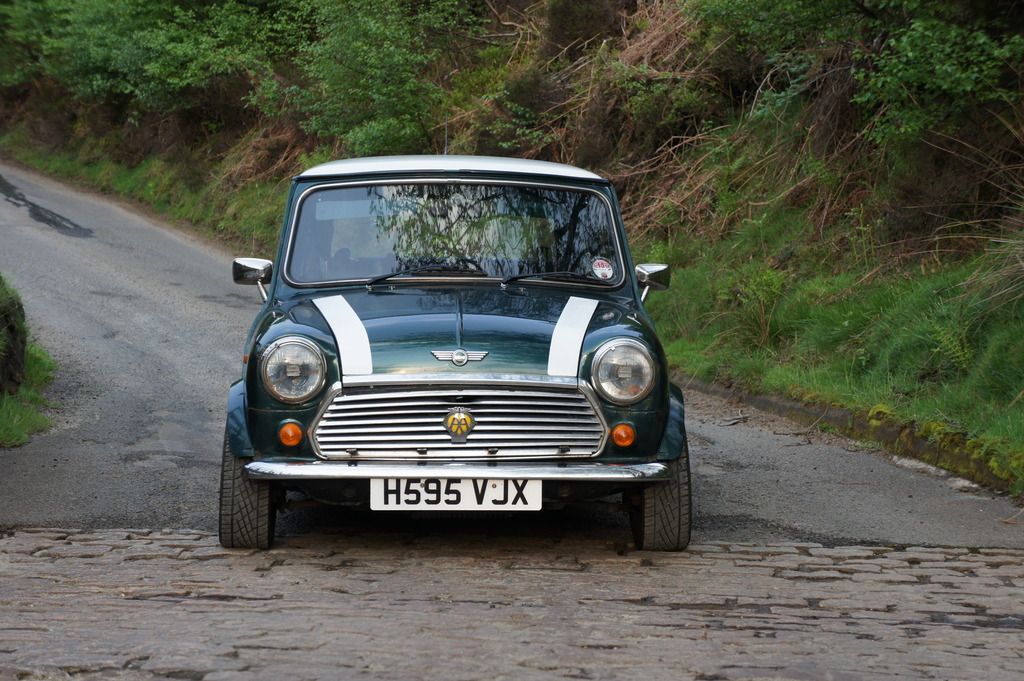
The car I’m starting with is my 1990 British racing green I’ve owned it about 8 years now and was my first car.


1%20shopped_zpscabvyfqj.jpg


DSC07901_zpshkvnpa5g.jpg


Edited by patto, 27 April 2020 - 09:28 PM.


#2 g111mds

g111mds

    Speeding Along Now

  • Members
  • PipPipPipPipPip
  • 432 posts
  • Location: Edinburgh

Posted 08 January 2017 - 07:27 PM

Sounds good. Sticking with the green and white combo?

#3 patto

patto

    Mini Mad

  • TMF+ Member
  • PipPipPipPip
  • 199 posts

Posted 08 January 2017 - 07:32 PM

The Engine and Gearbox

So I built the engine and box around 3 years ago and got it into the car about 3 month before I put it into storage (reluctantly).

The spec is as follows


Engine

998cc A+ bored +0.60 block pocketed

1275 12G940 head

Custom valves

Double valve springs

1:10.5 CR

Lightened flywheel

Lightened conrods

MED vernier duplex timing gear

Centre main strap

Kent 266 cam


Gearbox

Straight cut 4 speed

Central oil pickup

Fully rebuilt including diff

Kad quick shift


I can’t remember what final drive I put in it however I know it was too high so I’ll have to change that and I think I’ll swap to a cross pin diff while I’m at it. The only other thing I think I’ll do is get the head ported as I’d like to fit a small weber as I think it could still breathe a little better.


Anyway here are some photos


The block back from the machine shop

20131116_114633_zps3rhah3km.jpg


Something for anyone fitting a 1275 head to a small bore block is to check all the oil and water galleries line up, I had to blank two off and re-drill them.

20131116_114649_zpsc7kfyhcz.jpg


This is why the block needs pocketing.

20131006_140912_zpsbe5a1wji.jpg


A pile of most of the bits

20131209_171856_zpsgnegu8qz.jpg


This is quite typical of rovers machining, this had to be opened up to ensure a good oil flow

20131216_200557_zpstqo5eysx.jpg


The crank and main strap installed

20140120_215940_zpspqvdchif.jpg


The cam and timing gear fitted

20140208_120853_zpsifokeldj.jpg


A set of mildly lightened and smoothed rods

20140126_204805_zpsty2fde8t.jpg


Balancing the rods

20140126_195221_zpszgjxylem.jpg


Enlarging the gearbox to engine bolts

20140123_211730_zpsgb1ovoni.jpg


Measuring the combustion chambers 
20140129_174559_zpsbffcbu97.jpg


Cylinder head on and almost finished

20140221_191324_zpsqjeendlx.jpg


Straight cut box built unfortunately I didn’t get many photos of the box

20140317_201925_zpsvekvbsk2.jpg


Everything built up and ready for the car

20140310_194000_zpsejamw3j5.jpg


Dropped in and almost ready to go

20140420_163850_zpsvrpydzgl.jpg


So that was a very quick look at the engine build, I got it ran in and a few miles on it before it went into storage so it should be good to go once the rest of the car is done.


Edited by patto, 08 January 2017 - 07:36 PM.


#4 patto

patto

    Mini Mad

  • TMF+ Member
  • PipPipPipPip
  • 199 posts

Posted 08 January 2017 - 07:44 PM

This is a little project I did. I managed to get hold of some titanium from work so thought I’d make some subframe tower bolts and some rear subframe bolts.


IMG_20161025_171438_zpsmwktewd9.jpg


This is the bolt that’s too short so the first thing was to lop the head off it


IMG_20161025_171600_zps4pc4k8n8.jpg


And then bore out the centre to 25.5mm and stick some chamfers on it


IMG_20161025_183156_zpsxtqrqrxt.jpg


IMG_20161025_201552_zps7owblkve.jpg


Then i used this titanium valve stem which was quite handily 25.5mm to start with, i lopped a bit off and put a chamfer on it


IMG_20161025_194935_zps7rzz0zww.jpg


And then fitted them together, they are a very tight fit and the head gets put in the oven and the bar/shank put in the freezer to get them to fit. A quick blast round the head with a blow torch gets them to separate again. Chamfered on the back to.


IMG_20161025_201838_zpsermdi5mp.jpg


Next was to mill the head down to the correct size of 1 5/16 and put a flange on it


IMG_20161027_184512_zpsopz4vdgv.jpg


IMG_20161027_192330_zpsvkwrjrd6.jpg


Back together


IMG_20161027_212153_zpsvrbrlvnz.jpg


Then welded them up on both sides


IMG_20161028_160936_zpsrdcayixp.jpg


IMG_20161028_160949_zpsvlwrrbl8.jpg


And skimmed them off


IMG_20161029_125117_zpsl93xfbkt.jpg


IMG_20161029_125126_zpsm3ltfffy.jpg


I then turned the end down and threaded it


IMG_20161101_202153_zpsyezgadhe.jpg


And that’s about it, the new ones come out at 310 grams. I’m not sure what sort of saving that is, i had a look on the weights thread but could only find the double tower bolt version. So if anyone knows what the original ones weigh that would be great.


I also made the bolts for the front mount on the rear subframe.


IMG_20161101_202047_zpsx4m7aqyi.jpg


IMG_20161101_202101_zpsapj64r6o.jpg


IMG_20161101_182901_zpsbnmxjxzq.jpg


IMG_20161101_182914_zpstmwfszeb.jpg


#5 patto

patto

    Mini Mad

  • TMF+ Member
  • PipPipPipPip
  • 199 posts

Posted 08 January 2017 - 07:54 PM

I’m thinking of a very light blue similar to the French racing blue jaguar use, I think it will go very well with the carbon arches and roof.


#6 patto

patto

    Mini Mad

  • TMF+ Member
  • PipPipPipPip
  • 199 posts

Posted 08 January 2017 - 08:42 PM

I’m going to be going for an internal gear linkage so I thought I’d get a spare linkage housing sorted


I maybe got a little carried away with the drill however there is quite a lot of work gone into this.

IMG_20170108_163912_zpss4csls3v.jpg


Firstly I machined out the ends and pressed in some brass bushes to take all the play out the shafts, from what I’ve read if the housing is worn to start with then when you move it inside it just won’t work very well.

IMG_20170108_163954_zpsk1mlchuz.jpg


I also wanted the nifty little spring thing mini spares sells that centres the gear stick between 3rd and 4th as when I moved on to 5 speed cars I really struggled and kept going from 2nd to 5th so hopefully this should help with that. I’m not sure if this will actually work with this arrangement but I thought it’s worth a go. Obviously when the housing is moved inside the car you lose the top bar so I made a short one out of titanium for the spring to react against.

IMG_20170108_164036_zpsuyzljvga.jpg


I also plan on using my KAD quick shift, I’m not quite sure why no one uses them with an internal linkage but I plan on giving it a go. I found when it was fitted to the my other housing that it just touched the inside edge and would sometimes interfere with selecting gears, so I’ve milled out the ball joint area to give it a bit more clearance.

IMG_20161122_133757_zpsf5oqfckl.jpg


Other bits I’ve done is make new bushes out of nylon and to trim all the excess material from the bottom plate. I also got a couple of universal joints from china which are surprisingly good quality.

IMG_20170108_163928_zps6lfrqyyv.jpg


#7 cityspeed

cityspeed

    Mini Mad

  • Noobies
  • PipPipPipPip
  • 193 posts
  • Location: Essex

Posted 09 January 2017 - 09:30 AM

Amazing work, those tower bolts look like a work of art,
Keep up the drillium, there are some great threads on turbomini's where they have taken it to extremes

#8 pinkmini99

pinkmini99

    Super Mini Mad

  • Members
  • PipPipPipPipPipPip
  • 563 posts

Posted 09 January 2017 - 01:53 PM

Wow loving the internal gear linkage.

#9 mattmiglia

mattmiglia

    Super Mini Mad

  • Members
  • PipPipPipPipPipPip
  • 515 posts
  • Location: West Midlands

Posted 09 January 2017 - 09:35 PM

Very nice project, similar ideas and aim to mine. Those tower bolts are beautiful also!!! Will be following this with interest

#10 patto

patto

    Mini Mad

  • TMF+ Member
  • PipPipPipPip
  • 199 posts

Posted 11 January 2017 - 05:15 PM

My latest little project is a bracket to mount a rain light. This will go on the parcel shelf in the middle and will function as a fog light and high level brake light. The ideal is I’ll have it wired into the brakes normally and then a switch to put it on constantly. This means I should be able to get rid of that stupid great rectangular one off the valance.


I’ve been playing with a program called Google sketchup now for a few years and decided to put it to some use. I drew up a 3D drawing and played about with a few different designs for it. Ideally at this point I’d simply plumb it into a CNC milling machine and go for a cup of tea, unfortunately I don’t have a spare 10 grand so I’ll do it the old fashioned way.

Untitled_zpskqli6gmt.jpg


I converted the model into 3 flat images one of the top, front and bottom. I then printed it off on sticky back vinyl and stuck it on to some 3mm alloy.

IMG_20170110_201533_zpslykkjga4.jpg


After punching the holes and drilling them I used a fret saw to slowly cut out each section.

IMG_20161228_153319_zpsogvryk78.jpg


IMG_20161228_154142_zpsomw3miz7.jpg


Then I used needle files to finish them off. Once I had all 4 sections I welded them together and hey presto a rain light bracket.

IMG_20161229_1820022_zpspbbcurhm.jpg


IMG_20161229_1820232_zpswxbewfqk.jpg


#11 Rocket.

Rocket.

    One Carb Or Two?

  • Members
  • PipPipPipPipPipPipPip
  • 1,441 posts
  • Location: UK

Posted 11 January 2017 - 05:28 PM

Very nice!


Always like to see things being made from scratch


Keep up the good work


#12 GraemeC

GraemeC

    Crazy About Mini's

  • TMF+ Member
  • PipPipPipPipPipPipPipPipPipPip
  • 7,300 posts
  • Location: Carnforth

Posted 11 January 2017 - 06:05 PM

Impressive!


Although if I was following you in fog with that switched on I'd be using other words!  Is there not a maximum mounting height for a rear fog lamp?


#13 patto

patto

    Mini Mad

  • TMF+ Member
  • PipPipPipPip
  • 199 posts

Posted 11 January 2017 - 10:53 PM

Thanks for all the nice words guys. I’ve looked through the MOT rules and can’t find anything but also the light mounts to the bracket at a 10 degree angle which is meant to stop it dazzling people. I’ll see how it goes though if it’s too bright I'll change the resistor in it to dim it down a bit.


#14 patto

patto

    Mini Mad

  • TMF+ Member
  • PipPipPipPip
  • 199 posts

Posted 11 January 2017 - 11:58 PM

Oh sorry scratch that it can have a maximum height of 1m, probably cutting it fine but should be ok.


#15 pinkmini99

pinkmini99

    Super Mini Mad

  • Members
  • PipPipPipPipPipPip
  • 563 posts

Posted 12 January 2017 - 03:40 AM

I'm sure you have thought of this. If you switch the fog light on wouldn't it feed the brake lights too? I'm no wiring expert just in my head that's how it would work.


0 user(s) are reading this topic

0 members, 0 guests, 0 anonymous users