Jump to content


Photo
- - - - -

Rear Strut Ball Joint


  • Please log in to reply
38 replies to this topic

#16 MRA

MRA

    Previously known as 'mra-minis.co.uk'.

  • Banned
  • PipPipPipPipPipPipPipPipPipPip
  • 7,607 posts
  • Location: Due to move again....

Posted 28 May 2017 - 06:48 PM

......


Oh,, and apologies for not mentioning it earlier, the slightly easier way of fitting the cups to the arms, which I had almost forgotten, is to take a hot soldering iron and basically melt a shallow groove down the side of the cup, then with a sharp blade trim off any raised material. You now have a path to allow air to escape from under the cup, which helps. Don't overdo it, a groove that you can feel with your fingernail is all that you need. 10 thou deep, or so. They are still usually rather tight, which does no harm at all.


Very early arms reputedly had a very small vent hole drilled in the back to allow air out. The fact that it was definitely not there on any Mini post 1970 that I have owned suggests that it was dropped early in production. I wonder if it was a stress raiser, and initiated fractures? A rough, badly drilled hole can do that, and there is an amazingly high peak load on the area, but there are simple techniques to prevent it. Or maybe BMC were just too mean to drill the holes any more?

What ?  so you are advocating a bodge that could ultimately create a failure ?  I hope your insurance is valid, no not your car insurance !  your third party liability and public liability insurances !!! 


I have been rebuilding and also manufacturing Mini parts for more years than the majority on this planet have been alive and I have never seen a radius or top arm that doesn't have the tiny hole, but then all my arms get beadblasted then painted...  and as for "failure due to the surface finish of the hole"  oh come on you can do better than that....   the small drilled hole is always a better surface finish than the bearing bored  hole which is often quite a nasty finish.


Rear radius arms.....  I have worked on both types of fabricated arms from the very first to the last of the production arms including hydrolastic types as well, never seen one without a hole.


#17 tiger99

tiger99

    Crazy About Mini's

  • Members
  • PipPipPipPipPipPipPipPipPipPip
  • 8,584 posts
  • Location: Hemel Hempstead

Posted 28 May 2017 - 07:52 PM

What I advocated, making a tiny groove in the SIDE of the nylon cup to let air out is NOT a bodge. It is structurally on far safer grounds than drilling through the arm without knowing the facts. There is not much radial load on the cup. And if you want to go on about liability insurance, there are plenty of people on this forum who have advocated dangerous practices, and others who sell, whether deliberately or in sheer ignorance, dangerous products, not forgetting the monthly comic which gave particularly bad advice about setting up ball joints, which also has killed people, contrary to the Rover manual, and to any competent engineer's understanding of good practice. These people do represent a very real danger. I know that you are not one of them and you do understand what you are doing, by the way. By profession I am part safety analyst and a former colleague who advises me occasionally is a leading fatigue expert and safety analyst. I always err on the side of safety, which is why a few people on this forum hate me.


I am well aware that knuckle joint failure has killed people, and I am amazed that it has not happened recently, as it is evident that some on this forum have acquired cars that have been severely neglected in that area. The fatalities were due to the ball wearing through the cup (which I ALWAYS suggest that people check, although from the responses, I fear that few do, and are running around with the conical end of the cup gradually deforming against the spherical recess previously worn into the arm) and then into the arm, at which point it either wears right through or jams and breaks off, either of which results in an immediate suspension collapse. The fatal crashes most likely happened during hard cornering, when the failure was on an outside wheel, and knowledge of this was very common in the late 1960s.


If I did know for sure that it was ok to drill a very small hole, I would have done so, specifically to fit an electrical warning system for detecting cup wearthrough, as on my second Mini, neglect by the previous owner had ruined at least one arm. But as I said, I went looking for the holes and they could not be seen. I accept that you have seen many more arms than me, and they had holes, but facts are facts, both ways, and I don't think that either of us is blind. I don't know what to make of it. I daresay that a very occasional arm may have missed the drilling process, and QA was at times non-existent, but why did I end up with so many?


#18 MRA

MRA

    Previously known as 'mra-minis.co.uk'.

  • Banned
  • PipPipPipPipPipPipPipPipPipPip
  • 7,607 posts
  • Location: Due to move again....

Posted 28 May 2017 - 09:41 PM

What I advocated, making a tiny groove in the SIDE of the nylon cup to let air out is NOT a bodge. It is structurally on far safer grounds than drilling through the arm without knowing the facts. There is not much radial load on the cup. And if you want to go on about liability insurance, there are plenty of people on this forum who have advocated dangerous practices, and others who sell, whether deliberately or in sheer ignorance, dangerous products, not forgetting the monthly comic which gave particularly bad advice about setting up ball joints, which also has killed people, contrary to the Rover manual, and to any competent engineer's understanding of good practice. These people do represent a very real danger. I know that you are not one of them and you do understand what you are doing, by the way. By profession I am part safety analyst and a former colleague who advises me occasionally is a leading fatigue expert and safety analyst. I always err on the side of safety, which is why a few people on this forum hate me.


I am well aware that knuckle joint failure has killed people, and I am amazed that it has not happened recently, as it is evident that some on this forum have acquired cars that have been severely neglected in that area. The fatalities were due to the ball wearing through the cup (which I ALWAYS suggest that people check, although from the responses, I fear that few do, and are running around with the conical end of the cup gradually deforming against the spherical recess previously worn into the arm) and then into the arm, at which point it either wears right through or jams and breaks off, either of which results in an immediate suspension collapse. The fatal crashes most likely happened during hard cornering, when the failure was on an outside wheel, and knowledge of this was very common in the late 1960s.


If I did know for sure that it was ok to drill a very small hole, I would have done so, specifically to fit an electrical warning system for detecting cup wearthrough, as on my second Mini, neglect by the previous owner had ruined at least one arm. But as I said, I went looking for the holes and they could not be seen. I accept that you have seen many more arms than me, and they had holes, but facts are facts, both ways, and I don't think that either of us is blind. I don't know what to make of it. I daresay that a very occasional arm may have missed the drilling process, and QA was at times non-existent, but why did I end up with so many?

What cutting a groove down one side will or maybe more accurately can do is split as the loading in the base increases it distorts the plastic this split could allow the knuckle to move sideways, then impart a bending stress on the base of the knuckle, this would eventually lead to fatigue failure and a sudden drop like this would allow the wheel to contact the wheel arch then you will be forced by what the body work dictates and that is not normally where you want to go !


well you may have been unlucky and got some from a specific manufacturer that I haven't seen, rover used all manner of companies over the years...  but the hole would not be a stress issue. the arm would bend elsewhere first....


Electrical wear sensor ?  its got a manual one, just look for the slug of plastic poking through the hole, if no hole drill one in the centre drilled from inside would also align the drill with the centre, then chamfer both sides, if the hole is ragged, then ream it do not use a file as this leaves the cut lines in the wrong plane...


Edited by MRA, 28 May 2017 - 09:42 PM.


#19 Spider

Spider

    Moved Into The Garage

  • Admin
  • PipPipPipPipPipPipPipPipPipPipPip
  • 13,920 posts
  • Location: NSW
  • Local Club: South Australian Moke Club

Posted 29 May 2017 - 07:01 AM


Can't remember where I bought them. The old ones did need a steel rod down the strut and whacking with a hammer. The nylon cups where a right ******* to replace! They took some putting in! Maybe it is just down to cheap knuckle joint.


I've found some of the after market ones to be a few thousands over-size. I like to have the stem on the ball an easy slip fit in to the trumpet (or hilo). I always grease the stem too, to reduce corrosion (or rust in the case of hilos).


The nylon cups go in very easy if you clean the socket in the arm first. I just use a small wire wheel on the drill for this, then once again, I grease the nylon cup (on the outside) to aid it's fitting and also to stop rust. I then find if replacing again later, the cup slips out easy with the fingers.


Also, before fitting them, check how much grease is in the cup, they often have little more than a smear.


A few thousandths oversize ?  how do you know ?  I know you haven't got the drawing for this part as you would know that the tolerance is greater than a few thou !


I've measured them and corrected them.


Is that really all you could take from my post?


#20 MRA

MRA

    Previously known as 'mra-minis.co.uk'.

  • Banned
  • PipPipPipPipPipPipPipPipPipPip
  • 7,607 posts
  • Location: Due to move again....

Posted 29 May 2017 - 06:56 PM


Can't remember where I bought them. The old ones did need a steel rod down the strut and whacking with a hammer. The nylon cups where a right ******* to replace! They took some putting in! Maybe it is just down to cheap knuckle joint.


I've found some of the after market ones to be a few thousands over-size. I like to have the stem on the ball an easy slip fit in to the trumpet (or hilo). I always grease the stem too, to reduce corrosion (or rust in the case of hilos).


The nylon cups go in very easy if you clean the socket in the arm first. I just use a small wire wheel on the drill for this, then once again, I grease the nylon cup (on the outside) to aid it's fitting and also to stop rust. I then find if replacing again later, the cup slips out easy with the fingers.


Also, before fitting them, check how much grease is in the cup, they often have little more than a smear.


A few thousandths oversize ?  how do you know ?  I know you haven't got the drawing for this part as you would know that the tolerance is greater than a few thou !


I've measured them and corrected them.


Is that really all you could take from my post?


How can you correct something that you don't the size for ?


The point is you say they are oversize but its just a guess on your part, next thing we'll have people using angle grinders to "make them fit" when in reality there is no proof that they are the issue, it creates an issue where one wasn't previously present !  what method did you use ?  what root radius did you leave it with ? how about surface finish ?  what I took form your post was a potentially lethal modification that had been written about in a blase manner, nothing else on that post was an issue :)


Getting to the root cause and then taking the real issue back to the supplier / manufacturer has got to be the way to go, otherwise without feedback they will never know anything is wrong !


#21 Spider

Spider

    Moved Into The Garage

  • Admin
  • PipPipPipPipPipPipPipPipPipPipPip
  • 13,920 posts
  • Location: NSW
  • Local Club: South Australian Moke Club

Posted 29 May 2017 - 07:41 PM


What I advocated, making a tiny groove in the SIDE of the nylon cup to let air out is NOT a bodge. It is structurally on far safer grounds than drilling through the arm without knowing the facts. There is not much radial load on the cup. And if you want to go on about liability insurance, there are plenty of people on this forum who have advocated dangerous practices, and others who sell, whether deliberately or in sheer ignorance, dangerous products, not forgetting the monthly comic which gave particularly bad advice about setting up ball joints, which also has killed people, contrary to the Rover manual, and to any competent engineer's understanding of good practice. These people do represent a very real danger. I know that you are not one of them and you do understand what you are doing, by the way. By profession I am part safety analyst and a former colleague who advises me occasionally is a leading fatigue expert and safety analyst. I always err on the side of safety, which is why a few people on this forum hate me.


I am well aware that knuckle joint failure has killed people, and I am amazed that it has not happened recently, as it is evident that some on this forum have acquired cars that have been severely neglected in that area. The fatalities were due to the ball wearing through the cup (which I ALWAYS suggest that people check, although from the responses, I fear that few do, and are running around with the conical end of the cup gradually deforming against the spherical recess previously worn into the arm) and then into the arm, at which point it either wears right through or jams and breaks off, either of which results in an immediate suspension collapse. The fatal crashes most likely happened during hard cornering, when the failure was on an outside wheel, and knowledge of this was very common in the late 1960s.


If I did know for sure that it was ok to drill a very small hole, I would have done so, specifically to fit an electrical warning system for detecting cup wearthrough, as on my second Mini, neglect by the previous owner had ruined at least one arm. But as I said, I went looking for the holes and they could not be seen. I accept that you have seen many more arms than me, and they had holes, but facts are facts, both ways, and I don't think that either of us is blind. I don't know what to make of it. I daresay that a very occasional arm may have missed the drilling process, and QA was at times non-existent, but why did I end up with so many?

What cutting a groove down one side will or maybe more accurately can do is split as the loading in the base increases it distorts the plastic this split could allow the knuckle to move sideways, then impart a bending stress on the base of the knuckle, this would eventually lead to fatigue failure and a sudden drop like this would allow the wheel to contact the wheel arch then you will be forced by what the body work dictates and that is not normally where you want to go !


well you may have been unlucky and got some from a specific manufacturer that I haven't seen, rover used all manner of companies over the years...  but the hole would not be a stress issue. the arm would bend elsewhere first....


Electrical wear sensor ?  its got a manual one, just look for the slug of plastic poking through the hole, if no hole drill one in the centre drilled from inside would also align the drill with the centre, then chamfer both sides, if the hole is ragged, then ream it do not use a file as this leaves the cut lines in the wrong plane...


The Knuckle was modified here, post # 298


https://www.mokeforu...?topic=8423.285


and then a few weeks later, it was tested here;-


https://www.mokeforu...hp?topic=9337.0


over 10 000 km over some of Australia's worst 'roads', in a vehicle that weighed in approx 1200 kg. This Moke left his workshop with 1 km on the clock following a total rebuild, no time to test, it was run in on the way.


It's gone on to do a further trouble free 18 000 km over similar roads and tracks since this 'test' carrying similar weight.


I'll take a stab here and say 'it's OK'.


How do you know if I have the drawing or not?  Seems to me that you are making assumptions about things that you have no knowledge of.


Edited by Moke Spider, 29 May 2017 - 07:44 PM.


#22 tiger99

tiger99

    Crazy About Mini's

  • Members
  • PipPipPipPipPipPipPipPipPipPip
  • 8,584 posts
  • Location: Hemel Hempstead

Posted 29 May 2017 - 08:20 PM

And, the cup will not split and allow sideways movement of the ball. It is heavily constrained by the steel arm. The only dangerous failure modes in that area are the ball going through the bottom of the cup, jamming and breaking off, going right through the arm, which has happened, and the end of the trumpet succumbing to fatigue and/Or corrosion and breaking.

#23 MRA

MRA

    Previously known as 'mra-minis.co.uk'.

  • Banned
  • PipPipPipPipPipPipPipPipPipPip
  • 7,607 posts
  • Location: Due to move again....

Posted 29 May 2017 - 08:57 PM


What I advocated, making a tiny groove in the SIDE of the nylon cup to let air out is NOT a bodge. It is structurally on far safer grounds than drilling through the arm without knowing the facts. There is not much radial load on the cup. And if you want to go on about liability insurance, there are plenty of people on this forum who have advocated dangerous practices, and others who sell, whether deliberately or in sheer ignorance, dangerous products, not forgetting the monthly comic which gave particularly bad advice about setting up ball joints, which also has killed people, contrary to the Rover manual, and to any competent engineer's understanding of good practice. These people do represent a very real danger. I know that you are not one of them and you do understand what you are doing, by the way. By profession I am part safety analyst and a former colleague who advises me occasionally is a leading fatigue expert and safety analyst. I always err on the side of safety, which is why a few people on this forum hate me.


I am well aware that knuckle joint failure has killed people, and I am amazed that it has not happened recently, as it is evident that some on this forum have acquired cars that have been severely neglected in that area. The fatalities were due to the ball wearing through the cup (which I ALWAYS suggest that people check, although from the responses, I fear that few do, and are running around with the conical end of the cup gradually deforming against the spherical recess previously worn into the arm) and then into the arm, at which point it either wears right through or jams and breaks off, either of which results in an immediate suspension collapse. The fatal crashes most likely happened during hard cornering, when the failure was on an outside wheel, and knowledge of this was very common in the late 1960s.


If I did know for sure that it was ok to drill a very small hole, I would have done so, specifically to fit an electrical warning system for detecting cup wearthrough, as on my second Mini, neglect by the previous owner had ruined at least one arm. But as I said, I went looking for the holes and they could not be seen. I accept that you have seen many more arms than me, and they had holes, but facts are facts, both ways, and I don't think that either of us is blind. I don't know what to make of it. I daresay that a very occasional arm may have missed the drilling process, and QA was at times non-existent, but why did I end up with so many?

What cutting a groove down one side will or maybe more accurately can do is split as the loading in the base increases it distorts the plastic this split could allow the knuckle to move sideways, then impart a bending stress on the base of the knuckle, this would eventually lead to fatigue failure and a sudden drop like this would allow the wheel to contact the wheel arch then you will be forced by what the body work dictates and that is not normally where you want to go !


well you may have been unlucky and got some from a specific manufacturer that I haven't seen, rover used all manner of companies over the years...  but the hole would not be a stress issue. the arm would bend elsewhere first....


Electrical wear sensor ?  its got a manual one, just look for the slug of plastic poking through the hole, if no hole drill one in the centre drilled from inside would also align the drill with the centre, then chamfer both sides, if the hole is ragged, then ream it do not use a file as this leaves the cut lines in the wrong plane...


The Knuckle was modified here, post # 298


https://www.mokeforu...?topic=8423.285


and then a few weeks later, it was tested here;-


https://www.mokeforu...hp?topic=9337.0


over 10 000 km over some of Australia's worst 'roads', in a vehicle that weighed in approx 1200 kg. This Moke left his workshop with 1 km on the clock following a total rebuild, no time to test, it was run in on the way.


It's gone on to do a further trouble free 18 000 km over similar roads and tracks since this 'test' carrying similar weight.


I'll take a stab here and say 'it's OK'.


How do you know if I have the drawing or not?  Seems to me that you are making assumptions about things that you have no knowledge of.


There is nothing on that link showing a modification to the knuckle joint !  half the pictures have lost links so what good is that ?


I know as I said before that you don't have the drawings for the knuckle joint because you would of known that your (theoretical tolerance) was incorrect


I rest my case


#24 Spider

Spider

    Moved Into The Garage

  • Admin
  • PipPipPipPipPipPipPipPipPipPipPip
  • 13,920 posts
  • Location: NSW
  • Local Club: South Australian Moke Club

Posted 29 May 2017 - 09:44 PM


What I advocated, making a tiny groove in the SIDE of the nylon cup to let air out is NOT a bodge. It is structurally on far safer grounds than drilling through the arm without knowing the facts. There is not much radial load on the cup. And if you want to go on about liability insurance, there are plenty of people on this forum who have advocated dangerous practices, and others who sell, whether deliberately or in sheer ignorance, dangerous products, not forgetting the monthly comic which gave particularly bad advice about setting up ball joints, which also has killed people, contrary to the Rover manual, and to any competent engineer's understanding of good practice. These people do represent a very real danger. I know that you are not one of them and you do understand what you are doing, by the way. By profession I am part safety analyst and a former colleague who advises me occasionally is a leading fatigue expert and safety analyst. I always err on the side of safety, which is why a few people on this forum hate me.


I am well aware that knuckle joint failure has killed people, and I am amazed that it has not happened recently, as it is evident that some on this forum have acquired cars that have been severely neglected in that area. The fatalities were due to the ball wearing through the cup (which I ALWAYS suggest that people check, although from the responses, I fear that few do, and are running around with the conical end of the cup gradually deforming against the spherical recess previously worn into the arm) and then into the arm, at which point it either wears right through or jams and breaks off, either of which results in an immediate suspension collapse. The fatal crashes most likely happened during hard cornering, when the failure was on an outside wheel, and knowledge of this was very common in the late 1960s.


If I did know for sure that it was ok to drill a very small hole, I would have done so, specifically to fit an electrical warning system for detecting cup wearthrough, as on my second Mini, neglect by the previous owner had ruined at least one arm. But as I said, I went looking for the holes and they could not be seen. I accept that you have seen many more arms than me, and they had holes, but facts are facts, both ways, and I don't think that either of us is blind. I don't know what to make of it. I daresay that a very occasional arm may have missed the drilling process, and QA was at times non-existent, but why did I end up with so many?

What cutting a groove down one side will or maybe more accurately can do is split as the loading in the base increases it distorts the plastic this split could allow the knuckle to move sideways, then impart a bending stress on the base of the knuckle, this would eventually lead to fatigue failure and a sudden drop like this would allow the wheel to contact the wheel arch then you will be forced by what the body work dictates and that is not normally where you want to go !


well you may have been unlucky and got some from a specific manufacturer that I haven't seen, rover used all manner of companies over the years...  but the hole would not be a stress issue. the arm would bend elsewhere first....


Electrical wear sensor ?  its got a manual one, just look for the slug of plastic poking through the hole, if no hole drill one in the centre drilled from inside would also align the drill with the centre, then chamfer both sides, if the hole is ragged, then ream it do not use a file as this leaves the cut lines in the wrong plane...


The Knuckle was modified here, post # 298


https://www.mokeforu...?topic=8423.285


and then a few weeks later, it was tested here;-


https://www.mokeforu...hp?topic=9337.0


over 10 000 km over some of Australia's worst 'roads', in a vehicle that weighed in approx 1200 kg. This Moke left his workshop with 1 km on the clock following a total rebuild, no time to test, it was run in on the way.


It's gone on to do a further trouble free 18 000 km over similar roads and tracks since this 'test' carrying similar weight.


I'll take a stab here and say 'it's OK'.


How do you know if I have the drawing or not?  Seems to me that you are making assumptions about things that you have no knowledge of.


There is nothing on that link showing a modification to the knuckle joint !  half the pictures have lost links so what good is that ?


I know as I said before that you don't have the drawings for the knuckle joint because you would of known that your (theoretical tolerance) was incorrect


I rest my case


Locally, (and possibly in the UK?, though noted that Engineering Products also supplied some of the suspension parts too), the knuckle joints, ball joints and steering racks were made under license by TRW who also happened to be a client to me. While I was not able to obtain copies of these drawings (and it would be wrong of me to do so), I had access to them from which I have made sketches and taken appropriate notes.


The Ball was specified as EN8D Steel and hardened to 52 Rc. The shank dia was 0.497 to 0.500".


Martin, I've read a few of your posts on this forum. You appear to contribute little while wanting to argue considerably.


I rest my case.


#25 MRA

MRA

    Previously known as 'mra-minis.co.uk'.

  • Banned
  • PipPipPipPipPipPipPipPipPipPip
  • 7,607 posts
  • Location: Due to move again....

Posted 29 May 2017 - 10:36 PM

And, the cup will not split and allow sideways movement of the ball. It is heavily constrained by the steel arm. The only dangerous failure modes in that area are the ball going through the bottom of the cup, jamming and breaking off, going right through the arm, which has happened, and the end of the trumpet succumbing to fatigue and/Or corrosion and breaking.

If you had bothered to read my post I actually didn't say it definitely would crack but did say it could crack, and it can, because plastic modal failure is dramatically increased when a scratch to the parts skin goes through said skin, you are advocating a depth that will do that, will it crack ?  the answer is not on my Mini, because I wouldn't do it, neither would I allow it to be done to my customers cars or their parts, what ever you may think and say it is a ris, once it cracks it will start to move out of the top of the arm and the bottom section that the ball sits on will have little or no support, what are the chances of this happening ? 1 in 1,000 ? 1 in 10,000 ?  1 in 100,000 ???  who knows but I for one am not going to risk those odds because somebody somewhere could be seriously hurt or worse.


#26 MRA

MRA

    Previously known as 'mra-minis.co.uk'.

  • Banned
  • PipPipPipPipPipPipPipPipPipPip
  • 7,607 posts
  • Location: Due to move again....

Posted 29 May 2017 - 10:51 PM


What I advocated, making a tiny groove in the SIDE of the nylon cup to let air out is NOT a bodge. It is structurally on far safer grounds than drilling through the arm without knowing the facts. There is not much radial load on the cup. And if you want to go on about liability insurance, there are plenty of people on this forum who have advocated dangerous practices, and others who sell, whether deliberately or in sheer ignorance, dangerous products, not forgetting the monthly comic which gave particularly bad advice about setting up ball joints, which also has killed people, contrary to the Rover manual, and to any competent engineer's understanding of good practice. These people do represent a very real danger. I know that you are not one of them and you do understand what you are doing, by the way. By profession I am part safety analyst and a former colleague who advises me occasionally is a leading fatigue expert and safety analyst. I always err on the side of safety, which is why a few people on this forum hate me.


I am well aware that knuckle joint failure has killed people, and I am amazed that it has not happened recently, as it is evident that some on this forum have acquired cars that have been severely neglected in that area. The fatalities were due to the ball wearing through the cup (which I ALWAYS suggest that people check, although from the responses, I fear that few do, and are running around with the conical end of the cup gradually deforming against the spherical recess previously worn into the arm) and then into the arm, at which point it either wears right through or jams and breaks off, either of which results in an immediate suspension collapse. The fatal crashes most likely happened during hard cornering, when the failure was on an outside wheel, and knowledge of this was very common in the late 1960s.


If I did know for sure that it was ok to drill a very small hole, I would have done so, specifically to fit an electrical warning system for detecting cup wearthrough, as on my second Mini, neglect by the previous owner had ruined at least one arm. But as I said, I went looking for the holes and they could not be seen. I accept that you have seen many more arms than me, and they had holes, but facts are facts, both ways, and I don't think that either of us is blind. I don't know what to make of it. I daresay that a very occasional arm may have missed the drilling process, and QA was at times non-existent, but why did I end up with so many?

What cutting a groove down one side will or maybe more accurately can do is split as the loading in the base increases it distorts the plastic this split could allow the knuckle to move sideways, then impart a bending stress on the base of the knuckle, this would eventually lead to fatigue failure and a sudden drop like this would allow the wheel to contact the wheel arch then you will be forced by what the body work dictates and that is not normally where you want to go !


well you may have been unlucky and got some from a specific manufacturer that I haven't seen, rover used all manner of companies over the years...  but the hole would not be a stress issue. the arm would bend elsewhere first....


Electrical wear sensor ?  its got a manual one, just look for the slug of plastic poking through the hole, if no hole drill one in the centre drilled from inside would also align the drill with the centre, then chamfer both sides, if the hole is ragged, then ream it do not use a file as this leaves the cut lines in the wrong plane...


The Knuckle was modified here, post # 298


https://www.mokeforu...?topic=8423.285


and then a few weeks later, it was tested here;-


https://www.mokeforu...hp?topic=9337.0


over 10 000 km over some of Australia's worst 'roads', in a vehicle that weighed in approx 1200 kg. This Moke left his workshop with 1 km on the clock following a total rebuild, no time to test, it was run in on the way.


It's gone on to do a further trouble free 18 000 km over similar roads and tracks since this 'test' carrying similar weight.


I'll take a stab here and say 'it's OK'.


How do you know if I have the drawing or not?  Seems to me that you are making assumptions about things that you have no knowledge of.


There is nothing on that link showing a modification to the knuckle joint !  half the pictures have lost links so what good is that ?


I know as I said before that you don't have the drawings for the knuckle joint because you would of known that your (theoretical tolerance) was incorrect


I rest my case


Locally, (and possibly in the UK?, though noted that Engineering Products also supplied some of the suspension parts too), the knuckle joints, ball joints and steering racks were made under license by TRW who also happened to be a client to me. While I was not able to obtain copies of these drawings (and it would be wrong of me to do so), I had access to them from which I have made sketches and taken appropriate notes.


The Ball was specified as EN8D Steel and hardened to 52 Rc. The shank dia was 0.497 to 0.500".


Martin, I've read a few of your posts on this forum. You appear to contribute little while wanting to argue considerably.


I rest my case.


I contribute little ?  well if that is the case it is still preferable to your rampant meandering rubbish the drawing for this part is not 0.497" to 0.500" what are you talking about !!!  you are spouting bs in the hope that some of your followers believe you. EN8D you are deranged !  EN8D is an induction hardening steel and would NEVER be used for safety critical parts such as these !    Mate you need to stop before you dig yourself in any deeper.  You know it and I definitely know it ! 


These are an interference fit not a sloppy as a P**** in bucket fit ! 


Its nice that you resort to insults in an attempt to shut me up, I've seen too many fools like you that get way ahead of themselves you really let yourself down.


#27 midridge2

midridge2

    Camshaft & Stage Two Head

  • Members
  • PipPipPipPipPipPipPipPip
  • 1,794 posts
  • Location: north east england

Posted 30 May 2017 - 10:36 AM

Its a Forum about Minis not a forum about how well I know about engineering.
I recommend you answer the ops question and then stop fighting about your knowledge.


#28 MRA

MRA

    Previously known as 'mra-minis.co.uk'.

  • Banned
  • PipPipPipPipPipPipPipPipPipPip
  • 7,607 posts
  • Location: Due to move again....

Posted 01 June 2017 - 12:43 PM

Hi guys. Just sorting out rear suspension finally. Bought new ball joints for the rear struts(trumpets) the old ones took a little but not very much persuading to come out. How tight should the new ones be? I put them in and they slipped in no problem and I can easily pull them in and out. Is this normal?

Thanks

The design calls for an interference fit to a sliding fit, in other words you should be able to slide by hand to would need to gently press them in, preferably using a manual hand press as the force shouldn't need hydraulics.


#29 tiger99

tiger99

    Crazy About Mini's

  • Members
  • PipPipPipPipPipPipPipPipPipPip
  • 8,584 posts
  • Location: Hemel Hempstead

Posted 02 June 2017 - 02:46 PM

If the cup does split down the side, nothing bad happens. It is when its thick base wears through that the potentially dangerous failure modes start to progress.


#30 Spider

Spider

    Moved Into The Garage

  • Admin
  • PipPipPipPipPipPipPipPipPipPipPip
  • 13,920 posts
  • Location: NSW
  • Local Club: South Australian Moke Club

Posted 06 June 2017 - 11:09 PM


Locally, (and possibly in the UK?, though noted that Engineering Products also supplied some of the suspension parts too), the knuckle joints, ball joints and steering racks were made under license by TRW who also happened to be a client to me. While I was not able to obtain copies of these drawings (and it would be wrong of me to do so), I had access to them from which I have made sketches and taken appropriate notes.


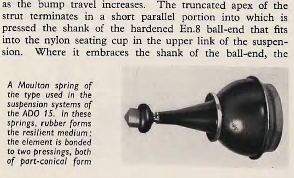
The Ball was specified as EN8D Steel and hardened to 52 Rc. ,,,,,,,,,,


I was kindly sent this last night and I found it interesting, though, no surprises.


KJ15_zpsg6oilpon.jpg


I don't have anymore but am reliably informed that this was from an article written by an engineering group from BMC and published in a British Engineering Journal in 1965.


0 user(s) are reading this topic

0 members, 0 guests, 0 anonymous users