Jump to content


Photo

Spi 1995 Huge Consumption, And Technical Control Refused


Best Answer gdudu , 27 October 2018 - 10:48 AM

Hello

Good new, the technical control for pollution was OK, The CO was about 0.3  :-)

Bad news :

The technical control was not accepted cause of oil drops. The new rules don't accep this, and the techicien told me that with an english car it would be impossible .... :angry:  :angry:  :angry:


And now, I have a problem when I accelerate : there is a big hole and the motor loses all power and frequently stalls


I have reseted the ECU with readmems (readmems.exe com3 interactive and OxFA), but this is the same


I have made a little log file attached

Go to the full post


  • Please log in to reply
156 replies to this topic

#1 gdudu

gdudu

    Stage One Kit Fitted

  • Noobies
  • PipPipPip
  • 54 posts
  • Location: Marseille

Posted 21 February 2018 - 07:33 PM

 
Hi everyone 
 
My english is not very good, so please I will try to explain
 
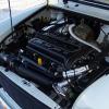
I have a french mini SPI, British open 1995, which is vey greedy with fuel.
 
It works very well, fast and no problem. Perfect start, even when time is cold as today (5°C). Iddle is very good and stable.
 
But it consume about 10 liters for 100 km, since about 2 or 3 years
 
Last month, I was to technical control, but the mini was refused, because of pollution, with CO at 0,50
 
My spark plugs are black, then I think I'm too rich
 
I have changed coiling T° sensor, I thought it was the reason
 
Last year I changed all the air leaks, and I just have checked them, they seem to be OK
 
Last week I bought an USB cable and with readmems.exe, I have read the ECU.
I put the data on Excel and I made some graphs. For me all sensor seems to be OK, then I don't understand where my problem is coming from.
 
Could someone watch thoses graphs and tell me if something's wrong ?
 
Thanks a lot 

Attached Files


Edited by gdudu, 21 February 2018 - 09:40 PM.


#2 viz139

viz139

    Super Mini Mad

  • Members
  • PipPipPipPipPipPip
  • 568 posts
  • Location: Ireland
  • Local Club: Irish Mini Owners Club

Posted 21 February 2018 - 10:21 PM

The problem with temperature sensors is usually the connector on the loom and not the sensor itself. I assume you have changed the air filter but is it a good quality one?

The only thing I see on the graphs is that the ignition advance max is about 30 deg. where I would expect the max on most minis to be about 36 deg.


#3 gdudu

gdudu

    Stage One Kit Fitted

  • Noobies
  • PipPipPip
  • 54 posts
  • Location: Marseille

Posted 21 February 2018 - 11:10 PM

Hi, thanks

No I didn't change the air filter now, I've changed it last year, buy to Datch.fr, I assume this is a normal filter

In France, for this year of vehicle (1995), the limit of CO is 0,3, and I have 0,4 after 3 longs try. The car was hot

The pictures I posted was a cool test, without going too fast

I've made another test with more power, and the max igniton advance is 36,5 deg


After some reads , I think I have a little problem with Intake air temp. It should be 35 °C. But can this explain my results ?


#4 Sprocket

Sprocket

    Great on Injection faults

  • Members
  • PipPipPipPipPipPipPipPipPipPip
  • 7,266 posts
  • Location: Warrington
  • Local Club: Manchester Minis

Posted 21 February 2018 - 11:37 PM

Firstly. Does coolant temperature reach 85 degrees?

Secondly. Does idle settle at 850rpm when fully warm?

Thirdly. What is frequency of lambda voltage change at idle?

#5 genpop

genpop

    Speeding Along Now

  • Members
  • PipPipPipPipPip
  • 472 posts
  • Location: Poppenhausen

Posted 22 February 2018 - 06:49 AM

Hi,when you have readmems, you could download memsanalyser and logger from rmrsoft.com. Try this software.

Like sprocket mentioned, check the idle speed. and check the purge valve if it closes on idle.It should open when over 75degree.


#6 martinrub

martinrub

    Stage One Kit Fitted

  • Noobies
  • PipPipPip
  • 50 posts
  • Location: Manchester

Posted 22 February 2018 - 10:08 AM

Hi, thanks
No I didn't change the air filter now, I've changed it last year, buy to Datch.fr, I assume this is a normal filter
In France, for this year of vehicle (1995), the limit of CO is 0,3, and I have 0,4 after 3 longs try. The car was hot
The pictures I posted was a cool test, without going too fast
I've made another test with more power, and the max igniton advance is 36,5 deg
 
After some reads , I think I have a little problem with Intake air temp. It should be 35 °C. But can this explain my results ?


There is definitely seems to be something wrong with the air intake temperature as interpreted by MEMS. That temperature should rise as the engine warms up, not fall. The ECU will therefore attempt to enrichen the mixture thinking there’s cold air coming in. We see that on the short trem fuel trim: it almost never gets above zero; the ECU is constantly commanding to lean off the mixture to keep the combustion at stociometric. Usually, you will see a roughly equal amount of STFT above zero as below. So the ECU is having a bit of a battle: the intake air temperature is telling it that it needs a richer mixture for the imaginary, incorrect cold conditions, and yet the feedback from the oxygen sensor is saying the ECU is giving too much fuel and so the ECU is reducing the amount of fuel to keep the mixture at 14.7:1 (or thereabouts).

The Haynes Chapter 14 says the air temperature sensor works on the NTC principle: as it warms up, its resisitance should fall. You could test that with a cup of warm water. It also says that the open-circuit supply to the sensor (ie sensor disconnected) is 5V. It might be worth testing that though the indications are that you have a good circuit. It says also that the voltage across the sensor (reconnected now) is between 2 V and 3 V at ambient, falling to 1.5 V at 40C. Perhaps you could back-probe the sensor and see what you get. At least you know the voltage should fall as the temperature rises. So, after you park the car when it’s hot and 2 minutes later, connect up the software, what does the air temperature read? If you leave the ignition on and the logfile running when you park the car, you normally see a steep rise in the intake air temperature - 40C and more - as the heat soaks into the air cleaner.


Is it possible that an incorrect temp sensor was fitted ie a PTC one instead of an NTC one?

I can’t sign off without mentioning how indebted I, for one am, to those very clever developers like Colin Bourassa, Al Richey, Leopold Genthner and Pawel Wozniczka (the Android MEMSDiag app developer). Without the brilliant work they’ve done, this would all be so much more difficult.

#7 Sprocket

Sprocket

    Great on Injection faults

  • Members
  • PipPipPipPipPipPipPipPipPipPip
  • 7,266 posts
  • Location: Warrington
  • Local Club: Manchester Minis

Posted 22 February 2018 - 11:45 AM

What we need is data from an idling engine with high resolution and indication on the time axis. That is where you problem lies.

Data logging means nothing if you do not capture the areas you are interested in. Resolution matters for example, the lambda sensor fluctuates at maybe 1 or 2 hz, data capture at 2 second intervals You miss most of the data you are interested in.

On a side note, what are the other emission gas readings? CO is only one, there are five.

CO
O2
CO2
HC (hydrocarbons)
NOX (not always measured depending on equipment)

Lambda value important too but is a calculated value rather than a measured gas.

I will post up the Rover emission check sheet later if someone doesnt do it before then, but you will need all the data mentioned above to use the check sheet accordingly.

As modern fuel systems become more and more complicated, there is becoming less and less need for garages to rely on exhaust gas measurements other than the basic readings, which the technicians now dont really seem to understand how to use that information. They are just looking at what a computer is telling them.

4 or 5 gas analysis seems to have fallen by the way side, but when used accordingly can narrow down the problem to just a few things. What goes in must come out. Understanding the chemical reactions and where they take place (combustion in the cylinder or reduction/ conversion in the catalytic converter) doesnt have to require a degree in chemistry.

Having the data from the ECU is still only one part of the picture I have to agree, the development work done so far with the latest pc based softwares having cracked MEMS diagnostics wide open from Rover Testbook, is amazing!! But 4 or 5 exhaust gas analysis is the final piece of the puzzle......

Edited by Sprocket, 22 February 2018 - 11:46 AM.


#8 martinrub

martinrub

    Stage One Kit Fitted

  • Noobies
  • PipPipPip
  • 50 posts
  • Location: Manchester

Posted 22 February 2018 - 02:05 PM

What we need is data from an idling engine with high resolution and indication on the time axis. That is where you problem lies.
Data logging means nothing if you do not capture the areas you are interested in. Resolution matters for example, the lambda sensor fluctuates at maybe 1 or 2 hz, data capture at 2 second intervals You miss most of the data you are interested in.
On a side note, what are the other emission gas readings? CO is only one, there are five.
CO
O2
CO2
HC (hydrocarbons)
NOX (not always measured depending on equipment)
Lambda value important too but is a calculated value rather than a measured gas.
I will post up the Rover emission check sheet later if someone doesnt do it before then, but you will need all the data mentioned above to use the check sheet accordingly.
As modern fuel systems become more and more complicated, there is becoming less and less need for garages to rely on exhaust gas measurements other than the basic readings, which the technicians now dont really seem to understand how to use that information. They are just looking at what a computer is telling them.
4 or 5 gas analysis seems to have fallen by the way side, but when used accordingly can narrow down the problem to just a few things. What goes in must come out. Understanding the chemical reactions and where they take place (combustion in the cylinder or reduction/ conversion in the catalytic converter) doesnt have to require a degree in chemistry.
Having the data from the ECU is still only one part of the picture I have to agree, the development work done so far with the latest pc based softwares having cracked MEMS diagnostics wide open from Rover Testbook, is amazing!! But 4 or 5 exhaust gas analysis is the final piece of the puzzle......


You’re dead right about data capture rates. With Pawel’s Android app, the rate is around once a second - I can’t be too sure - but the lambda traces are very notchy and aliasing is apparent. On the other hand, with the Windows programs: MEMSGauge, mems-rosco, MEMSAnalyser, the sampling rate is, on the logfile I’m just looking at, 2.33/sec. I did an exercise a while back: I connected up my PicoScope to the 02 sensor and simultaneously ran a logfile, which I then opened in MEMSAnalyser, and I compared the ‘scope waveform with the MEMSAnalyser waveform, and to my surprise, they were a really good match, not identical of course, but anyone who didn’t know might have believed the MEMSAnalyser waveform came from an oscilloscope. They would not have said that looking at a MEMSDiag lambda waveform.

#9 martinrub

martinrub

    Stage One Kit Fitted

  • Noobies
  • PipPipPip
  • 50 posts
  • Location: Manchester

Posted 22 February 2018 - 04:16 PM

You put the data into Excel, but is there any reason why you cant use MEMSAnalyser to
display your logfile?

MEMSAnalyser will display time along the x axis and it would allow us to see things like your lambda switching rate. Youd also be able to post the logfile, I guess, for others to look at with Al Richeys MEMSAnalyser.

#10 gdudu

gdudu

    Stage One Kit Fitted

  • Noobies
  • PipPipPip
  • 54 posts
  • Location: Marseille

Posted 22 February 2018 - 04:43 PM

Hi,

Thanks for all the responses !!!! Too speed for me, and I have some difficults to understand your strange langage  :D

I put data on Excel, only cause I like to understand what I read. Now, I know, then will go back with MemsAnalyser to make a try, at iddle, with a warm motor


I give you what I read on the controller paper :

At a speed iddle :

CO                O,50

Lambda        1,000

CO2              14,9

O2                 0,26

ppm vol HC   0020


At normal iddle :

CO                 O,51

CO2               14,7

O2                  0,26

ppm vol HC    0243

 
I don't think to be possible to have put an incorrect temp sensor. All seem to be original (except cooling liquid that I have changed)

For the intake air temp, last week (after technical control and before my recordings data) I have broken a little yellow pipe between air filter and somewhere I don't know. I have to replace it. Pearhaps it cause wrong air temp.


I will make a good recording soon and will post result here


Thanks


Edited by gdudu, 15 March 2018 - 08:51 AM.


#11 martinrub

martinrub

    Stage One Kit Fitted

  • Noobies
  • PipPipPip
  • 50 posts
  • Location: Manchester

Posted 22 February 2018 - 07:17 PM

The little yellow pipe - it might be a vacuum pipe. I cant see that would affect the air temperature sensor signal. Is it possible you made a mistake entering the air temperature data into Excel and there is nothing wrong with the sensor?

Anyway, the air temp signal is one thing you need to look at, and, if necessary, fix, and then see if short term fuel trim starts to look normal again. (With my coolant temp at 80 or more I have an air intake temperature of around 40C when driving (Rover 100)). I suppose a lot depends on your air cleaner and intake pipe layout.

But I wanted to mention the trouble I had for many years with poor emissions. I had an intermittent low compression on one cylinder. You could hear it if you listened carefully to the exhaust note. I only found it by chance when I filmed a compression test with an iPhone (because the needle moves just a bit too fast to see during the test). Then by chance I saw on one cylinder, one of the compressions didnt move the needle. I reconditioned the cylinder head including new valves and tappets. (I dont know for sure but I imagine there was a faulty tappet. ) My fuel consumption improved significantly after that, much to my surprise. But my spark plugs were good, although there was always a dark area on one of the plugs, which, with hindsight, later made sense.


Are your plugs black even after a long run? Even if your air temperature sensor signal isnt correct, your computer, in closed loop, still appears, from your data, to be compensating and adjusting for it using the oxygen sensor data.

Hopefully, people will look at your logfile and perhaps give you some more ideas.

#12 Sprocket

Sprocket

    Great on Injection faults

  • Members
  • PipPipPipPipPipPipPipPipPipPip
  • 7,266 posts
  • Location: Warrington
  • Local Club: Manchester Minis

Posted 23 February 2018 - 01:14 AM

Sorry, quality is a bit fuzzy.


Edited by Sprocket, 23 February 2018 - 01:15 AM.


#13 martinrub

martinrub

    Stage One Kit Fitted

  • Noobies
  • PipPipPip
  • 50 posts
  • Location: Manchester

Posted 23 February 2018 - 05:52 AM


Following Sprockets post of useful info, heres 3 links thatIve found useful on this subject:


http://www.crypton.c... emissions.html

https://www.georgias...on/SC2_1280.pdf

http://www.ratwell.c...ro/techgas.html

#14 gdudu

gdudu

    Stage One Kit Fitted

  • Noobies
  • PipPipPip
  • 54 posts
  • Location: Marseille

Posted 23 February 2018 - 10:05 AM

Hi, thanks for all data, I will need some time (weeks) to read all this (english is not easy for me)
 
My exhaust is OK, the tehnical center has checked it before making mesures (easyly, with a rag at the end to close it, and watching everywhere)
 
I have put a new vaccum pipe between intake temps sensor and intake air valve (I have some rigid crystal pipe)
 
And I made some mesures with readmems.exe and MemsAnalyser. The log data files are attached
 
1st mesure at iddle
My speed motor is between 720 and 800 rpm
My intake air temp is about 30°C
 
2nd mesure at a speed iddle (about 2500rpm)
Igniton advance is more than 30° ??
 
3rd mesure at motor stopped for test the throttle potentiometer
Throttle potentiometer goes between 30 and 99° ??


I think I could have a problem with throttle potentiometer ? 
And with ingniton advance (more than 30° at 2500rpm) ?

Attached Files


Edited by gdudu, 23 February 2018 - 05:24 PM.


#15 martinrub

martinrub

    Stage One Kit Fitted

  • Noobies
  • PipPipPip
  • 50 posts
  • Location: Manchester

Posted 23 February 2018 - 03:37 PM

I notice that your intake air temperature data (now) looks reasonable: it increases (very slightly) with time, and nearly 30C is reasonable.


Again we see your short term fuel trim at -12%, indicating a rich running condition, with MEMS subtracting fuel to try to keep the combustion and exhaust gases at the correct levels. In other words, confirmation of what you know: rich mixture. Ive attached a photo of my STFT taken under load at 3000rpm just to show how abnormal your level is. (I havent discovered how to paste in a photo into the text!)

Your throttle position readings seem high; however, I remembered high readings and emailed Al Richey (MEMSAnalyser/MEMSLogger) to check. He said there is a bug where it reports a reading twice as high. (However, mine reports as 18 deg at idle; yours shows as 28 deg.). So, almost certainly theres nothing wrong with the throttle position sensor - just divide by 2 and watch out for Al updating MEMSAnalyser. (Al has emailed Leopold (mems-rosco) and Colin Bourassa (MEMSGauge) and is working to ensure compatibilty across the range of programs that MEMSAnalyser reads, so, bear with it for now.)


Some of the faults that can cause rich running conditions:

1. Higher than normal fuel pressure
2. Faulty/leaking fuel pressure regulator
3. Evap/purge problems
4. Inlet air/Coolant temp sensor problems
5. MAP sensor problems
6. Faulty 02 sensor
7. Jumped timing belt


Ignition advance seems normal. Your coolant temp sensor and the inlet air temp sensor (now) seem normal. Your MAP sensor seems to be fine. The 02 sensor seems to be giving an output that looks very good to me, and the end result (after MEMS reacts to the signal from the O2 sensor) is a short term fuel trim that is subtracting fuel, which confirms what you know from your plugs, the fuel consumption and the high CO readings: the car is running rich.

So Im sorry to say, that looking at the logfile only seems to confirm what you know rather than tell me where the problem is. But perhaps someone else will see something I missed.

So perhaps you are back possibly to where you started. You could perhaps see if fuel is leaking out of the injector with the ignition on but the engine not running (but youd think if that was the problem irvwould affect idle more than high rpm).. You could also buy very cheaply on ebay a fuel pressure gauge with adapter to test the pressure. I bought one a coupke of years ago and cut the fuel line to the injector and insered the adapter, so now, inserting the gauge into the fuel line is simple. That might tell you if the regulator has stopped working. Mine (Rover 100) is a little over one bar.


0 user(s) are reading this topic

0 members, 0 guests, 0 anonymous users