Jump to content


Photo

Mk1 Austin Countryman


  • Please log in to reply
155 replies to this topic

#61 minimikej

minimikej

    Speeding Along Now

  • Members
  • PipPipPipPipPip
  • 346 posts
  • Location: Derbyshire

Posted 05 January 2019 - 09:12 PM


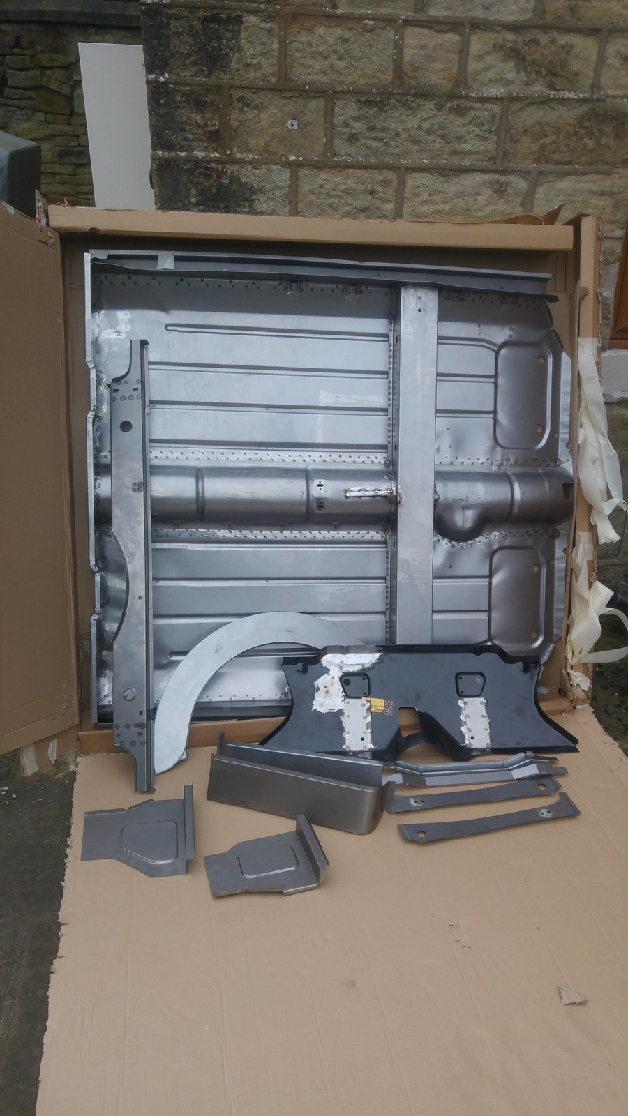
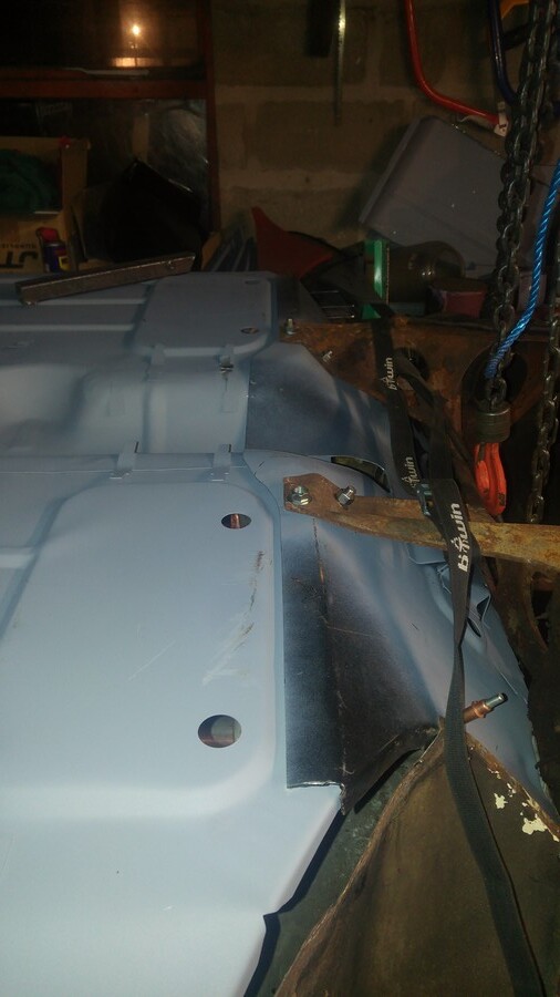
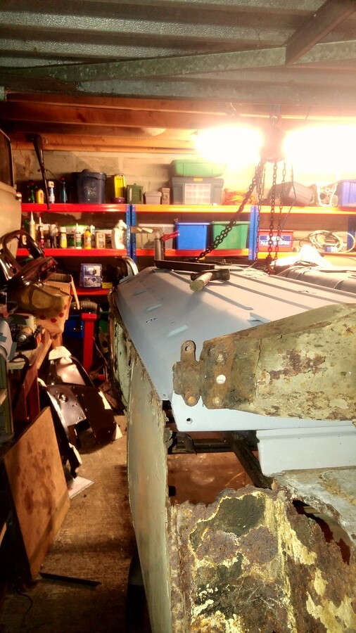
...there's something very wrong with that floor assembly they've supplied - almost as if the inner sills/floor returns have buckled under compression when the heel board was attached


Yup, almost too perfect to ripple bith sides at a simlar place, did it show signs of damage before prime?

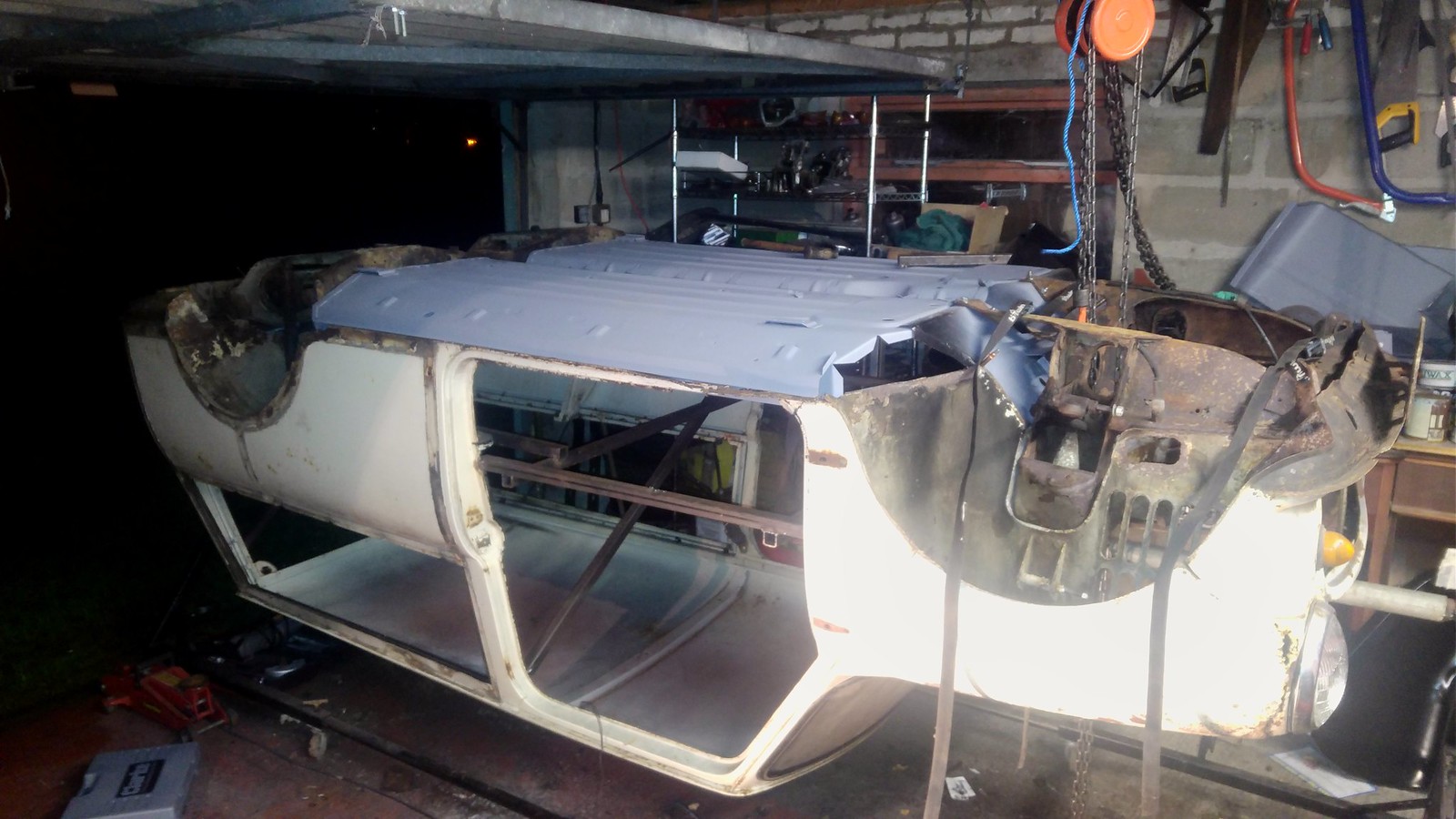
Looks a great project tho bud, keeping a close eye on this for inspiration


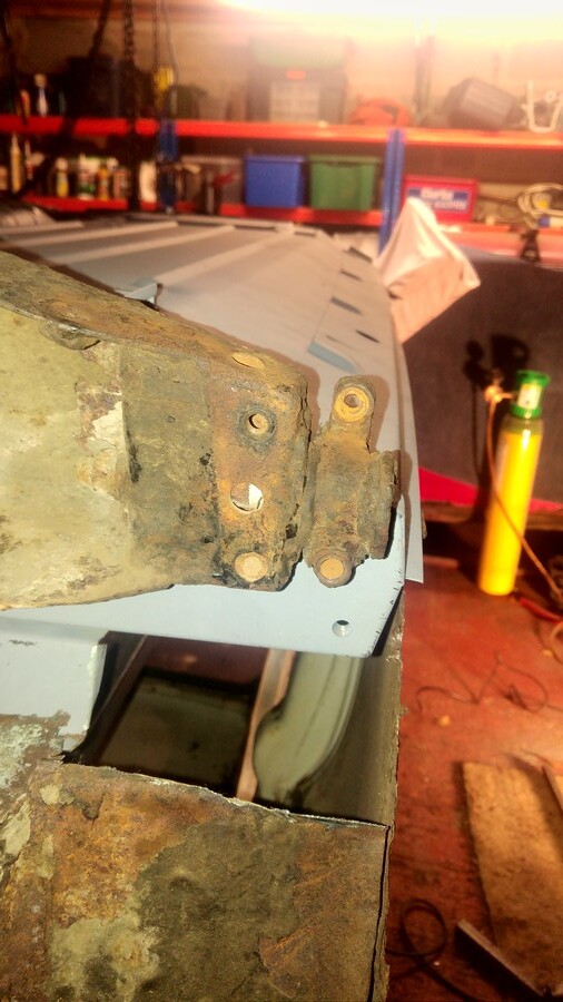
It is as was unwrapped. But I didn't eye-ball it along the sill length until I'd stashed it up there. I think this might be a consequence of the seam welding around the rear subframe mount reinforcement panel, heat distortion is my guess :/


#62 minimikej

minimikej

    Speeding Along Now

  • Members
  • PipPipPipPipPip
  • 346 posts
  • Location: Derbyshire

Posted 05 January 2019 - 11:08 PM

The unpack shot:

46569087292_67ba0f8f99_h.jpg2019-01-05_11-05-29 by Mike Jackson, on Flickr


#63 mini_in_progress

mini_in_progress

    Super Mini Mad

  • Members
  • PipPipPipPipPipPip
  • 641 posts

Posted 05 January 2019 - 11:17 PM

Ahhh yeah you can still see it there, is the floor, tunnel and inner sills not normally one piece with other bits added, yours looks to be made of all individual panels

Yeah the rear subby rein panel would be my guess top mate, looks to be rippled there, wouldnt want to cut it up but you may need to try and take the welds off and get the inner sill to move back a touch toward heelboard if it wont straighten. Unless you cut some material oy of the bend and weld it straight.

#64 minimikej

minimikej

    Speeding Along Now

  • Members
  • PipPipPipPipPip
  • 346 posts
  • Location: Derbyshire

Posted 06 January 2019 - 12:41 PM

All M-Machine complete floor pans are made out of tunnel, left and right floor halves with inner sill. The spot welds you can see along the inner sill length are for the outers. But the advantage over doing it yourself is that I think they're assembled on a jig so it's all square. Takes a bit of filler to make them look completely original.


I wouldn't be surprised if m-machine start selling complete floor assemblies based on the new Magnum one piece pressing, must be worth while for labour costs alone.


#65 mini_in_progress

mini_in_progress

    Super Mini Mad

  • Members
  • PipPipPipPipPipPip
  • 641 posts

Posted 06 January 2019 - 10:19 PM

All M-Machine complete floor pans are made out of tunnel, left and right floor halves with inner sill. The spot welds you can see along the inner sill length are for the outers. But the advantage over doing it yourself is that I think they're assembled on a jig so it's all square. Takes a bit of filler to make them look completely original.
 
I wouldn't be surprised if m-machine start selling complete floor assemblies based on the new Magnum one piece pressing, must be worth while for labour costs alone.


Yup. £250 on the bay gets you the one piece version. Dunno how good it is but i was considering it...

#66 minimissions

minimissions

    Up Into Fourth

  • Members
  • PipPipPipPipPipPipPipPipPip
  • 3,427 posts
  • Location: North West
  • Local Club: M.M.O.C

Posted 07 January 2019 - 06:47 AM

Wow that is panel collection haha love it! Looking forward to seeing this lot go in, that should just about sort the underside right out.


#67 minimikej

minimikej

    Speeding Along Now

  • Members
  • PipPipPipPipPip
  • 346 posts
  • Location: Derbyshire

Posted 12 January 2019 - 10:29 PM

Took the front subframe off again to add some tech-screws to help clamp the toeboard to the bulkhead.


Then set about removing the rear bins and tidying up the door step and inner sill flanges.


After which I got the floor in place for a trial fit:

39753102023_51363cc0d3_h.jpg2019-01-12_09-37-09 by Mike Jackson, on Flickr


Front bolts in loosely:


31776606007_90ae47dae6_h.jpg2019-01-12_09-37-29 by Mike Jackson, on Flickr


Couldn't get the heelboard to sit back down. This was because the touch points I'd welded into the bracing to index the cross member must be too low down towards the floor. Not surprising if things had sagged given how much of the original floor had gone before I got it so took them out and started lining up the heelboard:

46665380852_6b919f1c47_h.jpg2019-01-12_09-37-43 by Mike Jackson, on Flickr


31776613627_4f7f2ef3c8_h.jpg2019-01-12_09-38-06 by Mike Jackson, on Flickr


I've since aligned pan to rear subframe laterally. Drivers side front outer sill needs pushing downwards where it meets the doorstep to clear. Can't find my bottle jack.


Doesn't look much I know, but my wife tells me that was nearly 5 hours...


Cheers


Edited by minimikej, 12 January 2019 - 10:30 PM.


#68 minimissions

minimissions

    Up Into Fourth

  • Members
  • PipPipPipPipPipPipPipPipPip
  • 3,427 posts
  • Location: North West
  • Local Club: M.M.O.C

Posted 13 January 2019 - 07:45 AM

All this mucking about lining stuff up takes ages mike, it looks good just seeing a solid floor in place. Where do you get your roll over spit? looks ace..


#69 minimikej

minimikej

    Speeding Along Now

  • Members
  • PipPipPipPipPip
  • 346 posts
  • Location: Derbyshire

Posted 13 January 2019 - 10:45 AM

All this mucking about lining stuff up takes ages mike, it looks good just seeing a solid floor in place. Where do you get your roll over spit? looks ace..


There's lots to do. I'm going to have to very carefully grind what remains of the old sill flange off because it's adding a couple of millimetres towards the rear. Will definitely have to fashion up some pulley system to get it on and off, it wasn't easy lifting it into place on my own!


The rollover jig I bought from a garage in Failsworth somewhere. It's okay but a bit home-made. Managed to shear off the indexing pin so will have to reinforce it, and the castors that came with it are a bit flimsy.


#70 minimissions

minimissions

    Up Into Fourth

  • Members
  • PipPipPipPipPipPipPipPipPip
  • 3,427 posts
  • Location: North West
  • Local Club: M.M.O.C

Posted 14 January 2019 - 06:51 AM


All this mucking about lining stuff up takes ages mike, it looks good just seeing a solid floor in place. Where do you get your roll over spit? looks ace..


There's lots to do. I'm going to have to very carefully grind what remains of the old sill flange off because it's adding a couple of millimetres towards the rear. Will definitely have to fashion up some pulley system to get it on and off, it wasn't easy lifting it into place on my own!


The rollover jig I bought from a garage in Failsworth somewhere. It's okay but a bit home-made. Managed to shear off the indexing pin so will have to reinforce it, and the castors that came with it are a bit flimsy.


Yeah I bet but once the bottom end is in she will look ten times better. If I was closer I would have given you a lift with floor etc. I look forward to seeing the progress.


It does the job doesn't it, I need to sort a roll over jig for our project next so I can get back on with the welding and start the underside. Got a bit distracted with the new arrival haha


#71 country clubman

country clubman

    Mini Mad

  • Members
  • PipPipPipPip
  • 206 posts
  • Location: Paignton

Posted 18 January 2019 - 10:15 AM

Wow this looks like a lot of work you've got on your hands, good luck with this one. Don't know how original your going on this, but the floor never came in a one piece full length as per M-machine or  magnum(not talking about the tunnel joining, but the length front to back), they always had an extention piece on. So when fitting the full length m-machine floors you will always be able to see that a replacement floor has been fitted no matter how well it has been fitted, even with removing the seams where tunnel has been spot welded. Maybe as these mini's become more valuable the extention piece might be considered in the one piece units. If you've already fitted maybe bit late for me to make comment on this, or if this has already been a consideration just ignore me. This is the link for one at minisport, it has a good pic of it showing the swage markings that, the longer floor pans are missing, https://www.minispor...sion-piece.html


As for the jacking points they never had them on estates and vans, if you've got the old handbook it shows you jacking points for vans/estates which is on the subframes and it shows you specific points. I know already been answered but as you've got an old handbook it's always interesting to see where jacking points are on a estate.


#72 minimikej

minimikej

    Speeding Along Now

  • Members
  • PipPipPipPipPip
  • 346 posts
  • Location: Derbyshire

Posted 18 January 2019 - 07:25 PM

@Country Clubman - ok yes, understood. I'm working on squaring everything up with the M-Machine floor pan for now. It's a bit of a nightmare to be honest.

One of the reasons I went for an assembly was to hopefully trust something built square on a jig because of the amount of metal removed in its previous life.

That said, it looks to me like the heelboard subframe mounts are about 8mm too close together on the M-Machine assembly. I'll take some accurate measurements when I get some time in the garage. And there's a twist along the axis of the car, not much but it's discernible on a spirit level.

If it looks like I can square things up nicely I may then retro-fit the correct floor pan extension.


#73 minimissions

minimissions

    Up Into Fourth

  • Members
  • PipPipPipPipPipPipPipPipPip
  • 3,427 posts
  • Location: North West
  • Local Club: M.M.O.C

Posted 21 January 2019 - 06:48 AM

Hey Mike, I hope you can get it all lined up again soon, seems silly that it like you say it should be square and it isnt..


#74 minimikej

minimikej

    Speeding Along Now

  • Members
  • PipPipPipPipPip
  • 346 posts
  • Location: Derbyshire

Posted 21 January 2019 - 01:29 PM

Hey Mike, I hope you can get it all lined up again soon, seems silly that it like you say it should be square and it isnt..


Hi, I got the tape measure out.
According to this diagram: https://www.minimani...Master/scan.jpg


The heelboard upper bolts are 2mm too close together. Lower are about right give or take half a millimeter. So they're a bit like this:
    C-C 128.1cm
[/                          \]

    C-C 128.25cm


That 2mm narrow makes all the difference, I cannot coerce the existing squished bushes to fit let alone a new springy set.


I'll have to remove the upper captive bolts and re-weld. Really not happy with this assembly.


Cheers


#75 minimissions

minimissions

    Up Into Fourth

  • Members
  • PipPipPipPipPipPipPipPipPip
  • 3,427 posts
  • Location: North West
  • Local Club: M.M.O.C

Posted 21 January 2019 - 01:32 PM


Hey Mike, I hope you can get it all lined up again soon, seems silly that it like you say it should be square and it isnt..


Hi, I got the tape measure out.
According to this diagram: https://www.minimani...Master/scan.jpg


The heelboard upper bolts are 2mm too close together. Lower are about right give or take half a millimeter. So they're a bit like this:
    C-C 128.1cm
[/                          \]

    C-C 128.25cm


That 2mm narrow makes all the difference, I cannot coerce the existing squished bushes to fit let alone a new springy set.


I'll have to remove the upper captive bolts and re-weld. Really not happy with this assembly.


Cheers


Have your rang M-machine and mentioned this to them? Shame its not a good one, but looks like it might be an easy enough fix to move those bolts etc.


0 user(s) are reading this topic

0 members, 0 guests, 0 anonymous users