
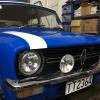
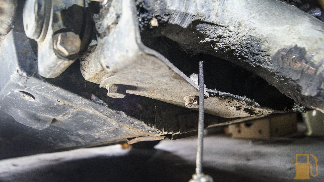
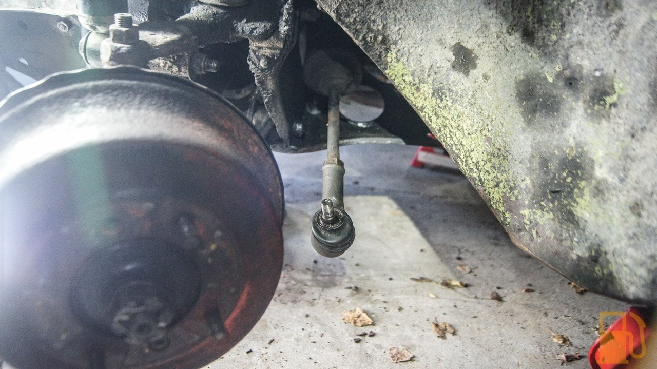
Its play in the end of the rack, not the tie rod end. I clarified that with the inspector as i was hoping it was just the tie rod end.
Part number 7, which Minispares lists as NLA


Stage One Kit Fitted

Posted 12 October 2018 - 08:40 AM
Its play in the end of the rack, not the tie rod end. I clarified that with the inspector as i was hoping it was just the tie rod end.
Part number 7, which Minispares lists as NLA
Super Mini Mad
Posted 12 October 2018 - 05:48 PM
One Carb Or Two?

Posted 13 October 2018 - 02:02 PM
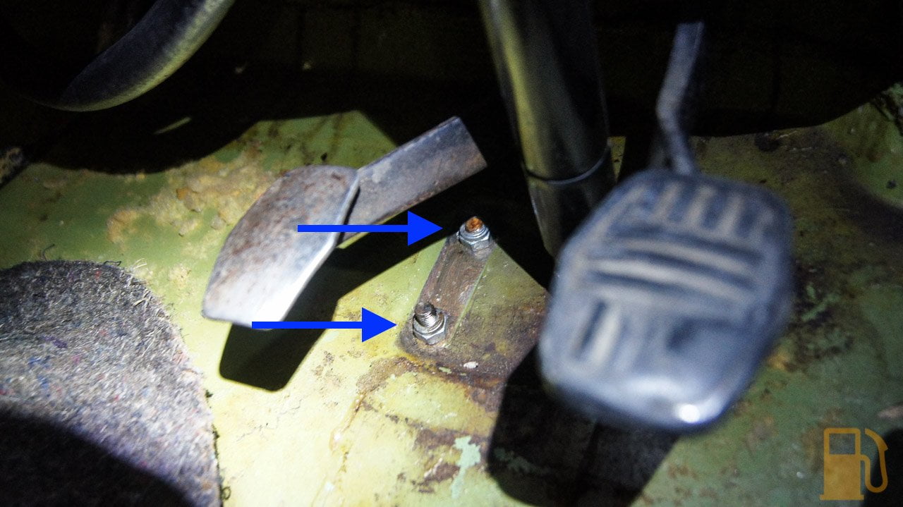
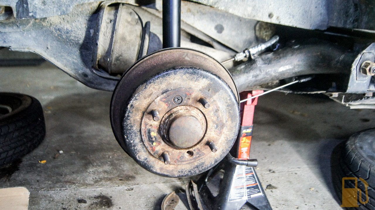
And fix the brake imbalance (LH 10% / RH 93% - Almost nothing from the left), which may be the hard one to do. I don't recall any obvious leaking etc when i last removed the drums, so will strip both down, clean the lot, and replace the rear hoses when I remove the arms. Hopefully there is something obvious that needs to be replaced.
Stage One Kit Fitted
Posted 14 October 2018 - 07:59 AM
And fix the brake imbalance (LH 10% / RH 93% - Almost nothing from the left), which may be the hard one to do. I don't recall any obvious leaking etc when i last removed the drums, so will strip both down, clean the lot, and replace the rear hoses when I remove the arms. Hopefully there is something obvious that needs to be replaced.
Likely to be a seized slave cylinder. Easy to change.
I hope so. Having not really done too much with drum brakes, other than overhauling the front ones, is testing the wheel cylinder as easy as just moving the piston and seeing how free it moves?
One Carb Or Two?
Posted 14 October 2018 - 11:50 AM
Stage One Kit Fitted
Posted 17 October 2018 - 07:57 AM


Stage One Kit Fitted
Posted 17 October 2018 - 07:59 AM
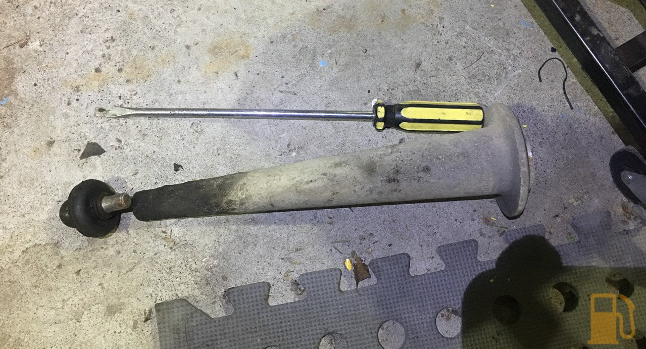
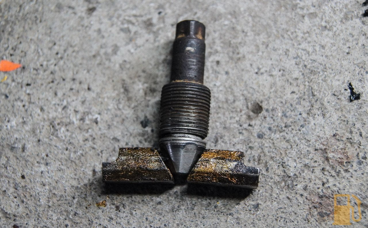
Take the drum off and get someone to push the brakes gently and slowly. Will be obvious if it isn't moving properly. It's about the only thing, apart from poor adjustment or worn out shoes, that can be wrong.
Take a snap of where the springs locate before you take the shoes off. Makes life much easier.
The only hard part is fitting the new clip on the back of the slave. Can be a sod.
You get the virtual cookie, the cylinder is seized as a stuck thing 
Stage One Kit Fitted
Posted 23 October 2018 - 08:35 PM


Stage One Kit Fitted
Posted 31 October 2018 - 06:04 AM


Stage One Kit Fitted
Posted 31 October 2018 - 06:08 AM


Up Into Fourth

Posted 31 October 2018 - 06:41 AM
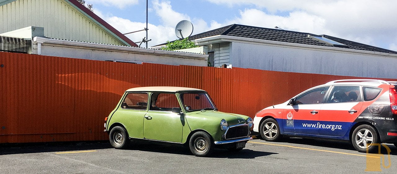
Excellent work!
You'll soon get used to the noise at 100kph, mine does over 4000rpm on the highway and will hold that for hours!
Stage One Kit Fitted
Posted 31 October 2018 - 06:56 AM
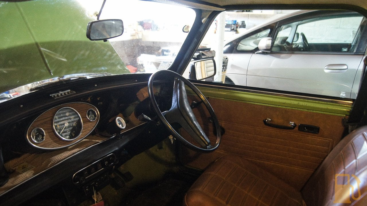
The shaking is the biggest issue on the open road atm. At around 90-110kph it can feel like the car is about to come apart. Need to see if its the wheels out of balance. Hell, it could even be the tires out of round from being old.
Edited by kws, 31 October 2018 - 06:56 AM.
Put's foolish ideas in peoples heads

Posted 31 October 2018 - 07:43 AM
Congrats on getting it back on the road. Enjoy it :)
Up Into Fourth
Posted 31 October 2018 - 08:46 AM
I had a problem with my steel wheels being out of round. You could see them wobble when you spun them, and when coating to a stop the car would jig up and down


Projects →
Mini Saloons →
1965 Austin Mini Restoration - Canadian Mk1Started by DoubleEh , 14 Nov 2022 |
|

|
||
Projects →
Mini Saloons →
Project Joe - 1991 Mini Mayfair 998Started by Eggers , 02 Jun 2022 |
|

|
||
Projects →
Mini Saloons →
Mpi Dashboad ProblemStarted by mikeprez , 22 Dec 2021 |
|
|
||
Projects →
Mini Saloons →
1978 Oew - Willy The MiniStarted by smalltreegrower , 11 Nov 2021 |
|

|
||
Projects →
Mini Saloons →
1968 Mk2 Cooper BuildStarted by Minime998 , 15 Sep 2021 |
|

|
0 members, 1 guests, 0 anonymous users


