Jump to content


Photo
- - - - -

Dual Circuit Brake Conversion


  • Please log in to reply
35 replies to this topic

#31 Globule

Globule

    One Carb Or Two?

  • Members
  • PipPipPipPipPipPipPip
  • 1,134 posts

Posted 16 June 2020 - 06:23 PM

Please correct me if I am wrong, but you now have the GMC227 (yellow tag), fronts are direct to the brakes and the rears are passing through the MS72 to limit the pressure to the rears? 

Did you keep the brake limit valve (FAM7821)?


Couldn't figure out how to quote from another thread, but from Moke Spider http://www.theminifo...lain-something/
 

You can fit up the Yellow Tag with an Adjustable Valve in the Rear Circuit only, or any manner of Rear Brake Control Valves out there and it will work fine. The two Pistons of the two Circuits in the Master Cylinder are not mechanically coupled, but Hydraulically coupled. So, in Operation, the Pedal pushed the lower Piston first and the upper Piston stays put, one there is pressure built up in the system from the lower Piston, then the upper Piston will start to move.


So, if plumbed the way recommended for a Yellow Tag (lower Port to the Rears, and upper port to the Fronts), the Rear Brakes will come on first, once they have pressure in the System, then it will bring on the Fronts, once the pressure in the System increases to the point where the Rear Brake Control Valve (of what ever type you choose) reaches it's shut off Pressure, all Pressure in the System will then go in to the Front Brakes.


Did you consider the 13H7757 inertia valve or did you want the adjustment in the circuit? It seems they are out of stock, but I would rather not spend the £90 for the MS72 if I didn't have to. I just need working brakes really! 

Thanks,


Edited by Globule, 16 June 2020 - 06:24 PM.


#32 Pete649

Pete649

    Speeding Along Now

  • TMF+ Member
  • PipPipPipPipPip
  • 371 posts
  • Location: Isle of Man

Posted 17 June 2020 - 06:55 AM

Please correct me if I am wrong, but you now have the GMC227 (yellow tag), fronts are direct to the brakes and the rears are passing through the MS72 to limit the pressure to the rears?

 
That is my current plan, although the parts are not fitted yet.
 

Did you keep the brake limit valve (FAM7821)?


No.
 

Did you consider the 13H7757 inertia valve or did you want the adjustment in the circuit?


That part is NLA and I wanted to be able to manually adjust the cut-off pressures to the rear, although I know that the inertia valve can be 'adjusted' by changing it's installation angle.

None of the above are a recommendation, it is the path I have personally chosen to take with the braking system on my car.


#33 Ethel

Ethel

    ..is NOT a girl!

  • TMF Team
  • PipPipPipPipPipPipPipPipPipPipPip
  • 25,416 posts
  • Local Club: none

Posted 17 June 2020 - 07:58 AM


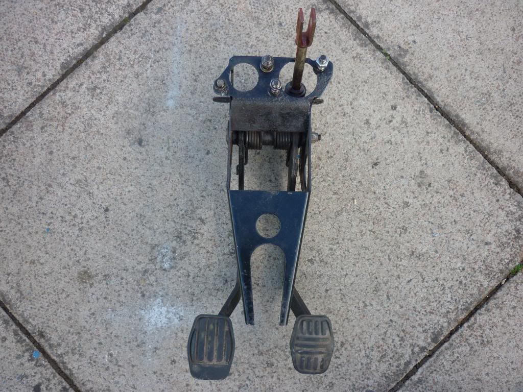
The dual circuit one has a forked  bit that is clamped by the steering column bracket. The earlier type is shorter and fixed with a couple of bolts through the parcel shelf.

Is there any chance you have a comparison photo between the two? I have one pedal box to use on my project and have no idea what it is, I thought the only difference was servo vs non servo but guess I was wrong! 


This is the later one - with the 2 "prongs" between the foot pads. The earlier one is cut square across above where the hole is between the prongs and has a couple of bolt holes instead. You should also be able to identify 'em by the pedal rubber shape, Small 'n square is the earlier single circuit type.


The FAM7821 valve's advantage is that, as it uses pressure in the front circuit to close of the rear, if the front circuit fails you'll be able to work the rear brakes harder than would normally be possible.


The yellow band master will increase the bias towards the front brakes over previous master cylinders because of its stepped bore. You could also swap the rear wheel cylinders to give more, or less, bias.


If it's a road car, there are so many variables I'd only consider an inertia valve as likely to be an all round improvement for wet/dry, loaded/unloaded rear seats etc.

01269c520186293a4ceac69ef48e1e97877c8332


#34 Globule

Globule

    One Carb Or Two?

  • Members
  • PipPipPipPipPipPipPip
  • 1,134 posts

Posted 17 June 2020 - 09:19 AM


The dual circuit one has a forked  bit that is clamped by the steering column bracket. The earlier type is shorter and fixed with a couple of bolts through the parcel shelf.

Is there any chance you have a comparison photo between the two? I have one pedal box to use on my project and have no idea what it is, I thought the only difference was servo vs non servo but guess I was wrong! 


This is the later one - with the 2 "prongs" between the foot pads. The earlier one is cut square across above where the hole is between the prongs and has a couple of bolt holes instead. You should also be able to identify 'em by the pedal rubber shape, Small 'n square is the earlier single circuit type.


The FAM7821 valve's advantage is that, as it uses pressure in the front circuit to close of the rear, if the front circuit fails you'll be able to work the rear brakes harder than would normally be possible.


The yellow band master will increase the bias towards the front brakes over previous master cylinders because of its stepped bore. You could also swap the rear wheel cylinders to give more, or less, bias.


If it's a road car, there are so many variables I'd only consider an inertia valve as likely to be an all round improvement for wet/dry, loaded/unloaded rear seats etc.

01269c520186293a4ceac69ef48e1e97877c8332


Thank you for the photo, mine looks the same as this bar the arm (for the clevis pin) at the top, this is just for the servo attachment isn't it? I.e. The GMC227 (yellow tag) will connect direct to the pedal? Sorry for the basic question, it has been years since I have fitted one of these and even then it was a servo unit!

In this case, can I just use a GMC227 to feed into the FAM7821 and from there just split (with relevant Y pieces) to the individual wheels with no further valves etc? It is for turbo a series, road use and will be a fixed load most of the time. 

Thanks Pete for coming back to me. 


Edited by Globule, 17 June 2020 - 11:10 AM.


#35 Ethel

Ethel

    ..is NOT a girl!

  • TMF Team
  • PipPipPipPipPipPipPipPipPipPipPip
  • 25,416 posts
  • Local Club: none

Posted 17 June 2020 - 03:34 PM

Yes,


That worked for the factory so no reason why it won't work for you. Remember the lower outlet on the yellow band cylinder is for the rear circuit & is threaded M12x1 - another reason to stick with the FAM7821 if you have one as a pipe kit with the oddball union is readily available. The rear circuit ports on the FAM7821 are the pair that are offset from each other. The one nearest the end of he casting goes to the wheel cylinders.


#36 Pete649

Pete649

    Speeding Along Now

  • TMF+ Member
  • PipPipPipPipPip
  • 371 posts
  • Location: Isle of Man

Posted 17 June 2020 - 04:19 PM

You could also swap the rear wheel cylinders to give more, or less, bias.


I should add that I have no idea what the rear wheel cylinder diameters currently are on my car and consequently I may find that with the fitting of the MS72 proportioning valve that I do not have enough adjustment (not enough bias either way) so I may well end up fine tuning this by changing the rear wheel cylinders for different sizes as required, as suggested by Ethel.


Edited by Pete649, 17 June 2020 - 04:21 PM.


1 user(s) are reading this topic

0 members, 1 guests, 0 anonymous users