I've done this before using a jpg to dxf converter (tried to draw up mini subframes in CATIA), but the accuracy can be sloppy. Depends entirely on the input image.
You will end up with a dxf full of points to cleanup, and the location of each point will depend entirely on the pixels in the image (if you wanted it t be easier you would need some pretty high level AI in the converter to recognaise with sufficient precision your part and determine which pixels to include and which to exclude).
Also determining scale can be an issue without a reference. This is why vector files exist.
All these issues will affect the final machined part (crap in = crap out). You would need to take into account what tolerances your part needs to be fabricated within to know how much "conversion" error margin you have.
Can I ask what you are trying to make, and what exactly is your jpg (engineering drawing? actual part?)
Edited by superchiwawa, 11 May 2019 - 10:47 PM.


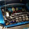
 ). so I want to transfer this image into a file where I can get lines and points, surfaces aren't really an issue with this, as it would be all profile milling.