Word, I pretty agree with everyone. My sentiment is simply to give it a whirl the simple way, and if problems develop, reevaluate the design.


Yankee Ev Conversion
Started by
Tremelune
, Sep 28 2019 06:40 AM
83 replies to this topic
#47

Ethel
-

- TMF Team
-

- 26,638 posts
..is NOT a girl!
- Local Club: none
Posted 05 January 2020 - 12:46 PM
Too right, all this armchair engineering is fun, but ultimately somebody has to get off their arse and have a go to achieve anything. You have my respect for doing that.
#48
R1mini
-

- Members
-
- 1,387 posts
One Carb Or Two?
Posted 06 January 2020 - 02:30 PM
Just wondering, if you use another frame based on the mini design aren't you going to have the exact same problems running out of space where the steering rack is?
I personally would continue with your mini subframe, by the way the towers lean back 4.5 degrees when fitted in the car
If you need more space where the lower suspension mounts are some people convert them to rose joints for more space for the CV's see below
https://picclick.co....ml#&gid=1&pid=5
Just out of interest I saw this article which uses a newly developed electric motor in a classic mini subframe
https://www.msn.com/...ocid=spartanntp
Cheers
David
#49
Tremelune
-
- Members
-
- 154 posts
Mini Mad
- Location: Los Angeles
Posted 08 January 2020 - 02:17 AM
the towers lean back 4.5 degrees when fitted in the car
Thank you for this—this is rather important niche knowledge.
The problem with those aftermarket power plants is that they cost more than all the other parts of my conversion combined...
#50
DeadSquare
-

- Members
-
- 3,381 posts
Up Into Fourth
- Location: Herefordshire
- Local Club: Unipower GT Owners Club
Posted 08 January 2020 - 10:19 AM
Just out of interest I saw this article which uses a newly developed electric motor in a classic mini subframe
https://www.msn.com/...ocid=spartanntp
Cheers
David
WOW !
That only weighs 1/2 a Mini lump.
Twin engine / four wheel drive / 200+ BHP...................away we go.
#51
Tremelune
-
- Members
-
- 154 posts
Mini Mad
- Location: Los Angeles
Posted 24 January 2020 - 06:37 PM
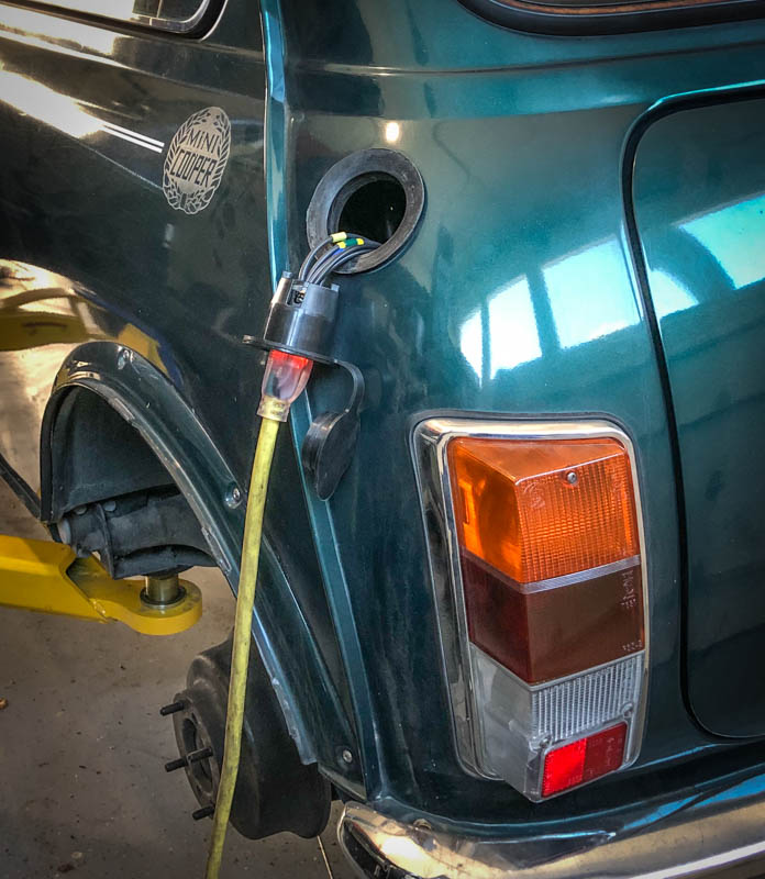
Charging is underway!
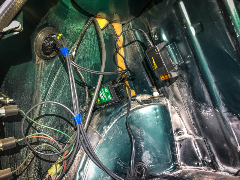
I was getting precious with my wiring and it was taking forever, so I switched to full on prototype mode, just throwing wires around to get things working...I'll make it nice once it's on the road and functioning properly...I've had to change things numerous times already, and I expect there's more to come.
Because I'm not using a DC-DC converter yet, I wired a battery tender in to keep the 12v battery charged as well...It's fun plugging an old Mini into the wall!
It's beginning to become difficult to make good progress without having the motor installed, and I've been eyeballing the subframe pretty hard. If I cut out part of the axle hole without cutting where the lower arm attaches, it might still work with some reinforcement. I have some time on my hands, so I might give it a whirl anyway. Worst case, I muck up a $500 subframe trying to save on a $2k subframe...Seems worth the effort.
Edited by Tremelune, 24 January 2020 - 06:38 PM.
#52
schelle63
-

- Noobies
-
- 29 posts
Passed Test
- Location: Siegen
Posted 25 January 2020 - 12:25 PM
Progress! Very nice to see.
Is this a "Thunderstruck"-charger? (Are you not using the original charger/DC-DC/BMS,....?)
Prototype-mode is exactly what applied to my project; after 9 months on the road and so many changes, the car still continues to be a protoype. 
Kep it up!
Markus
#53
Tremelune
-
- Members
-
- 154 posts
Mini Mad
- Location: Los Angeles
Posted 25 January 2020 - 05:15 PM
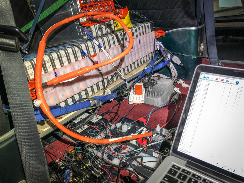
Correct! It's their TSM2500 with their
charge controller and BMS.
I would have loved to use the Nissan charger, DC-DC, and BMS—it would have saved me thousands—but they're not quite hacked yet, it seems. https://www.diyelect...e DC-DC working, but took the video down (and it wasn't comprehensive). It would be amazing if someone could figure out the charger CAN bus protocol, but it's just not there yet. I might try and give it a whirl myself the next time around, 'cause you can pick up a 6.6kW Nissan charger for a few hundred bucks...You just can't control it outside a Leaf!
Most of the CAN hacking on the Leaf is being done to add features to the Leaf. That's...effectively the opposite of my goals of using Leaf components in the wild.
#54
schelle63
-
- Noobies
-
- 29 posts
Passed Test
- Location: Siegen
Posted 26 January 2020 - 01:24 PM
You should have a look into the norwegian e-driver's forum: elbilforum.no
There is a huge community as they have so many cars for so many years. Someone there may have access to the Leaf's CAN protocol.
(You might even stay with the original Nissan's components, and the optional 6.6KW charger.)
Regards,
Markus
#55
Tremelune
-
- Members
-
- 154 posts
Mini Mad
- Location: Los Angeles
Posted 10 March 2020 - 02:18 AM
The MCM subframe has arrived! It's spacious, but I'm suddenly daunted with regard to positioning the motor...It's hard to know where it should sit. Like, where should the axle outputs be vertically with regard to the subframe...
I really wish I'd taken more measurements and photos before I took the car apart. Current plan is to confirm that the axles should be centered in the stock holes, and measure that relative to the towers, and use that as the reference on the McGee subframe...
I might also install it on the car and see if I can find those chassis measurements and go from there...The sticky bit with that is the "spars" on the McGee subframe intrude upon the Mini body. For Honda swaps, you have to just cut those chassis bits out, but for my swap it's unnecessary...but that means I'll have to cut the McGee subframe and re-weld in supports. Not too big a deal, but the more I have to modify this thing, the more it seems I should have just cut the stock subframe to hell and then reinforced it after the motor was in...Blarg.
Once I have some good reference points, I'll use wooden inclined planes to position the motor, manila folder pieces to mock up mounts, then fab everything up and weld it together. NO PROBLEM
#56
Tremelune
-
- Members
-
- 154 posts
Mini Mad
- Location: Los Angeles
Posted 11 March 2020 - 04:24 AM
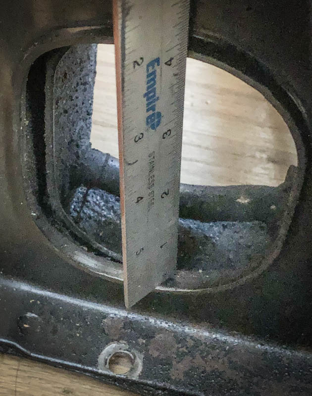
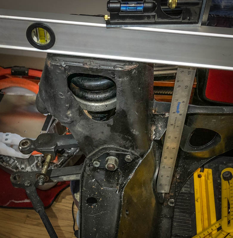
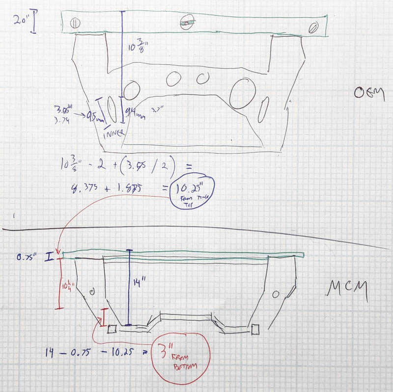
Utilizing Paper Aided Design (PAD) and non-laser measuring tools, I was able to figure out where the center of the output shafts are vertically, relative to the tower tops. I'm basing this all on the assumption that axle center should be at the height of the center of the OEM axle holes.
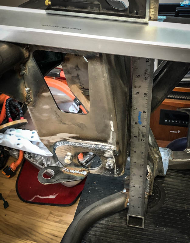
The plan is to position the axle outputs at 3" above the lower square tubing of the MCM subframe, and as far back as I can without the motor hitting the body. I might try and weld up a little set of gunsight irons to help me position the motor...If they line up on both sides and are centered, the motor should be straight, level, and at the right height...but I might be getting a bit precious about all this.
Random info: The MCM subframe is 42 lb.
Edited by Tremelune, 11 March 2020 - 04:30 AM.
#57
Tremelune
-
- Members
-
- 154 posts
Mini Mad
- Location: Los Angeles
Posted 25 March 2020 - 05:29 PM
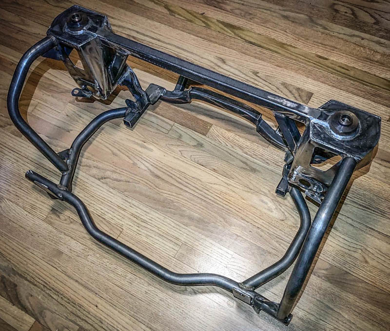
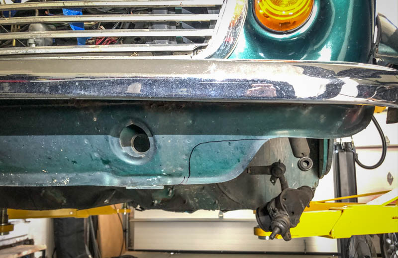
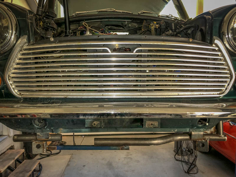
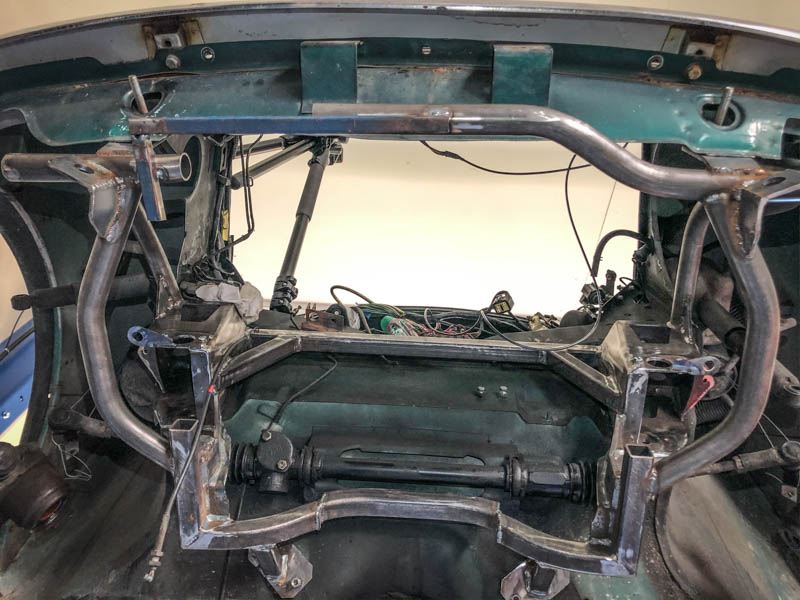
Fitment check on the McGee subframe!
I was measuring things up for motor mounts and realized I still had some questions about where the body was relative to the subframe, so I put it on the car. I had to cut out the inner fenders some (I cut more than I needed to, but I found it difficult to measure) as well as a bit of the front lip. None of it is really necessary for the Leaf motor, but is for the Honda subframe. If I had to do it over again, I would have put more effort into the factory subframe before buying aftermarket, but I'm American so why listen to others when you're already right?
It was kind of a pain to mount up. The method I found that worked was to do the rear first. I raised both sides up a bit with wood blocks, raised it by hand onto one of the mount bolts and put a nut on when a few threads were through (with the front mounts hanging completely beneath the car), then did the other side, then squeezed the front mounts behind the lip, then the towers...This was easier said than done, with some olympic balance, foot, and finger work involved...It would have been extremely helpful to have someone else to help maneuver the subframe and press down on the mounting bolts to keep them from poking back into the car when trying to push the subframe onto them. I had to pry the body a smidge below the shock mounts to make sure the towers fit inside when being tightened upwards (they were catching the lip, and bending them up/in).
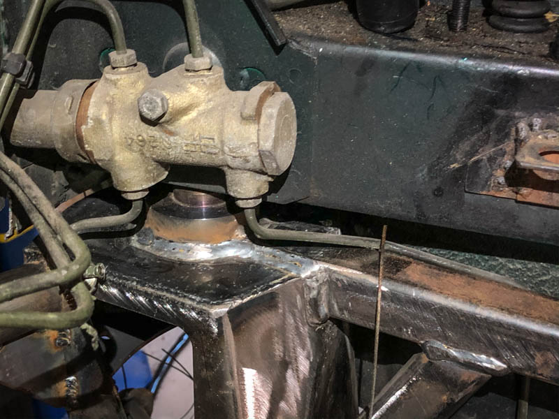
One of the brake lines was about a 1/2" too short...It's possible I could have torqued the subframe up and bent it into place, but it made me nervous enough to detach it...I'm not quite sure what to do about that. I can either roll a new brake line all the way from the back of the car, or put it in front of the crossmember, requiring the brake line to be detached every time the subframe is lowered. I guess that's rare, but it seems like a bummer to also have to bleed the brakes. Thinking again, the worst case scenario is that I'll break/crimp a line that I'd have to replace anyway, sooo...Might just give that another whirl.
#58
fuzzy-hair-man
-

- Members
-
- 181 posts
Mini Mad
- Location: Armidale NSW
- Local Club: Minis in the Gong
Posted 28 March 2020 - 10:41 PM
I was looking at some YouTube's of other leaf conversions, out seems the leaf motor and transmission package is kinda short, I think I'd try to mount the diff as centrally as possible by pushing the motor as far to the right hand side of the vehicle as possible this should minimize any angle on the driveshafts as the shafts will be longer for the same distance forward.
I'd them address any weight imbalance with chargers / inverters / dc to dc / batteries etc.
I'd them address any weight imbalance with chargers / inverters / dc to dc / batteries etc.
#59
nightflier
-

- Members
-
- 519 posts
Super Mini Mad
- Location: Malvern
Posted 30 March 2020 - 08:11 PM
Hey Tremelune, finally caught up with you. Been following your project on EV forums for a little while, as I was looking at a Leaf conversion for a while.
I went with a different electric motor, but now have to start matching up all the other bits to suit. I guess it's part of the fun ?
I went with a different electric motor, but now have to start matching up all the other bits to suit. I guess it's part of the fun ?
#60
nightflier
-
- Members
-
- 519 posts
Super Mini Mad
- Location: Malvern
Posted 30 March 2020 - 08:12 PM
Hey Tremelune, finally caught up with you. Been following your project on EV forums for a little while, as I was looking at a Leaf conversion for a while.
I went with a different electric motor, but now have to start matching up all the other bits to suit. I guess it's part of the fun ?
I went with a different electric motor, but now have to start matching up all the other bits to suit. I guess it's part of the fun ?


1 user(s) are reading this topic
0 members, 1 guests, 0 anonymous users


