Amazing. Clever idea to 3D print a model for testing etc

It Started As An Intellectual Exercise
Started by
Trog
, Jan 17 2020 11:01 PM
107 replies to this topic
#46

hazpalmer14
-

- Members
-

- 682 posts
Super Mini Mad
- Local Club: cumbria mini cruisers
Posted 22 January 2020 - 09:44 AM
#47
Trog
-
- Just Joined
-
- 91 posts
Stage One Kit Fitted
Posted 22 January 2020 - 10:20 AM
This is great stuff, hats off.
Are the valve spacings standard ? And is the exhaust port modelled straight off a 5port head end port ?
Phil.
The valve spacing is standard, but remember the valve order is reversed on no 2 & 4 Cylinders!
Yes exhaust port is based on a flowed endport.
#48
Steve220
-

- Members
-
- 4,885 posts
Up Into Fourth
- Location: Shropshire
- Local Club: RAF Mini Club
Posted 22 January 2020 - 11:09 AM
This is next level stuff!! Fantastic effort!!
#49
Spider
-

- Admin
-
- 13,899 posts
Moved Into The Garage
- Location: NSW
- Local Club: South Australian Moke Club
Posted 22 January 2020 - 06:39 PM
This is next level stuff!! Fantastic effort!!
No.
It's a few more than that !
#50
Stealth72
-

- Just Joined
-
- 25 posts
Passed Test
- Location: Marshland St James, Norfolk
Posted 22 January 2020 - 07:04 PM
I wish that there was a “love” button!!
Fantastic work.
I was at Coventry doing Automotive Engineering in the early 90’s. At the time it was the only place that offered such a course. I started with dreams of becoming the next Gordon Murray/John Barnard; I have ended up being an auto-electrician....
Keep up the great work!
Fantastic work.
I was at Coventry doing Automotive Engineering in the early 90’s. At the time it was the only place that offered such a course. I started with dreams of becoming the next Gordon Murray/John Barnard; I have ended up being an auto-electrician....
Keep up the great work!
#51
Norway Thomas
-

- Just Joined
-
- 18 posts
Learner Driver
- Location: Fiskarstrand
- Local Club: Norsk Mini Cooper Club.
Posted 22 January 2020 - 10:59 PM
It would be interesting to know what a camshaft, head, manifolds, thermostat housing etc would cost.
I regret mentioning the fan being on backwards but one was asked to spot the deliberate mistake.
Like others I am might impressed by the work put into this.
#52
Trog
-
- Just Joined
-
- 91 posts
Stage One Kit Fitted
Posted 22 January 2020 - 11:46 PM
It would be interesting to know what a camshaft, head, manifolds, thermostat housing etc would cost.
I regret mentioning the fan being on backwards but one was asked to spot the deliberate mistake.
Like others I am might impressed by the work put into this.
Truth is I hadn't realized the fan was on backwards! The deliberate mistake was the dip stick! which is now fixed, and came out really well and very easily too. Sometime you get a win!
It's too early for costs! Cam and Exhaust are off the shelf. If I do make some the cost will depend on the quantity made...
And don't forget standard A+ Rods don't clear an 8 port cam! Bet you didn't know that I was halfway through this before I found out, S rods can be modified a bit to clear but if you go A+ then you need new "competition" rods with bolts rather than the stud and nut on the standard rods.
#53
jonny f
-
- Members
-
- 1,485 posts
One Carb Or Two?
- Location: Surrey
- Local Club: Boxhill Mini Club
Posted 23 January 2020 - 12:07 PM
Very interesting reading. Look forward to the next installment
#54
mini13
-
- Members
-
- 3,802 posts
Up Into Fourth
Posted 23 January 2020 - 03:52 PM
I knew that... due to a bad experience with a cam belt... 
absolutley cracking effort! also I bet that took a while to print out on the 3d printer!
And don't forget standard A+ Rods don't clear an 8 port cam! Bet you didn't know that I was halfway through this before I found out, S rods can be modified a bit to clear but if you go A+ then you need new "competition" rods with bolts rather than the stud and nut on the standard rods.
#55
Trog
-
- Just Joined
-
- 91 posts
Stage One Kit Fitted
Posted 24 January 2020 - 06:38 AM
Chapter 3 "Rozzer is having a problem with his differential" Part 1
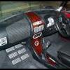
With a prototype head I was able to dry build the engine in the car and start to develop the complete package of the engine bay:
 01 package.jpg 98.29K
2 downloads
01 package.jpg 98.29K
2 downloads
02 package.jpg 99.08K
0 downloads
03 package.jpg 96.1K
0 downloads
04 package.jpg 95.23K
1 downloads
The exhaust was “off the shelf” so not a problem (Though I still need one if anyone happens to have one lying around!!!), however the inlet manifold would be a whole different story. I would also need to design a thermostat housing and package things like the oil cooler, coil pack, and fuel pressure regulator. I also wanted to add expansion and recovery tanks to the cooling system. Finally, I would need to add all the sensors and wiring for the EFI system.
The EFI system I am using is a Megasquirt, primarily because a colleague at work had one he had bought but not used. It is a sequential firing system so I will need a multiple coil pack and a cam position sensor as well as the other sensors injectors and other malarkey.
The thermostat housing was the first thing to be designed, this was always going to be a casting. Initially this was the same height as the mini head and used a mini spacer for the heater take off. However, as I worked through the hose fitting, I realised I needed to rotate the top housing about 20 degrees and the spacer no longer aligned properly. So, I made a tall housing that included the heater outlet. This also allowed me to add bosses for the water temperature sensors and fan switch.
Thermo Housing.jpg 28.19K
1 downloads
08 Built.JPG 67.83K
1 downloads
09 Built.JPG 41.95K
0 downloads
07 Built.JPG 53.9K
1 downloads
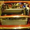
3D printing made this whole process so much easier, the speed of design, iteration, and re-design was awesome! You can also see the oil cooler position in this image, I used an RSP Cooper cooler after much research! But that’s another story.
Finally, I made a radiator mounting bracket and called that job done! Hose is standard Cooper, the thermostat housing is in a slightly different position, but the hose still works, though I do need a new one!
#56
Trog
-
- Just Joined
-
- 91 posts
Stage One Kit Fitted
Posted 24 January 2020 - 06:40 AM
Chapter 3 "Rozzer is having a problem with his differential" Part 2
Next was the inlet manifold. I can’t tell you how many hours I spent on this. A lot of this was “old school” engineering; making mock-ups from carboard, plastic pipe, even foam pipe insulation, experimenting with all sorts of packages. The images are of early CAD work to help with feasibility, sadly I have no pictures of the actual mock-ups!
Plenums.jpg 51.3K
6 downloads
The main problem was trying to get the inlet runners as long as possible. Ideally 12 to 18 inches (in old speak). The “up and over” worked well though it drove the injectors into the manifold, but it would require a modified bonnet so was unacceptable. With a forward plenum chamber the issue was finding space for the throttle body and air filter as the long run pushed the plenum down and then the alternator pushed it towards the right of the car.
This iteration process slowly brought me to a design where the plenum was above the alternator with a central inlet underneath which turned 90 degrees to the right to put the Throttle body above the starter motor. This did make the runners shorter than I hoped but it packaged well under the hood and allowed enough room for the throttle body (off an MGF) and air filter. On an aside I used the K&N filter area calculator, the filter you will see on the images is about 200% of the surface area!
010.JPG 42.13K
6 downloads
Even with this extra space The HVAC duct was in the way! I was reluctant to remove this completely, so I made a new one out of glass fibre that gave me the extra couple of inches required
HVAC.jpg 29.09K
3 downloads
#57
Trog
-
- Just Joined
-
- 91 posts
Stage One Kit Fitted
Posted 24 January 2020 - 06:42 AM
Chapter 3 "Rozzer is having a problem with his differential" Part 3
Once I had the final package solution, I had to change that into a viable design. I will show you the steps now, but this actually went on concurrently with the next few chapter(s) where I will cover casting and machining the head. (I have no idea how many chapters there will be, I’m making this up as I go along.)
The manifold, as shown above, is a single piece. How could I make this? If it is too hard to make do I split it into an assembly and if so, how many parts and where do I make the split. Finally, how do I make all the separate parts.
Looking at a single part, well I could cast it but that’s one big casting and once made leaves no room for modification etc.. So, no not a casting. What about a fabrication? Well it could made from Aluminium but as I can’t weld or fabricate aluminium (my steel welding ain’t so good either!) that would be expensive but would at least be modifiable. FRP is an option, but would take a lot of work, I have never made anything that large before. So, a single piece seemed to be out of the question.
The most common way to split the system is into a plenum chamber and inlet tracts so this is the direction I chose. I decided on a split line between the two parts, keeping all of the plenum volume in one part. Much CAD and prototyping helped me to get a shape for the plenum chamber: As a general rule the plenum chamber should be about the same volume as the engine displacement for a normally aspirated 4 stroke engine. This is actually quite small and a hard target to achieve!
Initially I was going to make 4 short cast inlets Joined by a laser cut backplate. 4 velocity stacks would smooth the airflow. However, it became apparent that a single casting would be cheaper and easier to make so that was the final direction I took. One of the drivers for the multi part inlet was to aid assembly and plug changes however during the development I realised that the easiest way to get to the plugs was to remove the complete inlet assembly rather than disassembly parts of it! Yes, it’s a bit tricky to do but with all the limitations I had to work around some compromises seemed inevitable. The way I have mitigated this is to use Iridium plugs that last about 100,000 km.! I am thinking I don’t mind removing the manifold every 10 years to change the plugs!
The plenum is made from GRP; I made a 3D print of the inside of the plenum, I then overlaid it woven glass mat before adding 2 steel reinforced flanges and then a final few layers of woven mat. Once finished the 3D print was broken up and removed.
001.jpg 31.45K
1 downloads
002.jpg 32.91K
2 downloads
Finally, I was able to find places for the coil pack and fuel pressure regulator. These look a bit snug to the brake master cylinder but have sufficient clearance to ensure that they will not contact due to engine movement
On the dry build images there is a grey bracket that runs across the front of the engine under the plenum. There is a pin on this which locates onto the plenum. The function of this is to support the inlet system that is cantilevered off the head. While the weight is not too great; during driving the vibrations and potential resonations could cause a failure, especially of the GRP. This pin that locates onto a rubber bushed hole will absorb these. You will see this sort of design on a number of production cars. I have also found that it makes assembling the manifold a lot easier, once located onto the pin the manifold stays put while you put the 8 bolts in!
Enough I hear you cry, I will leave the chapter there!!!
#58
yeti21586
-

- TMF+ Member
-
- 3,714 posts
He's A Lumberjack And He's OK
- Name: Chris
- Location: Hampshire
- Local Club: None
Posted 24 January 2020 - 07:32 AM
Your work and attention detail is amazing! I wish I had even half of your design skill and drive, to think up a project is one thing. But to design it, make prototypes and then have it cast! That takes true dedication and commitment.
I will wait with anticipation for the next installment. I can't wait to see it working and hear the noise, I love an 8port
YetI
I will wait with anticipation for the next installment. I can't wait to see it working and hear the noise, I love an 8port
YetI
#59
r.tec
-

- Members
-
- 160 posts
Mini Mad
- Location: Muenstereifel
- Local Club: SfG Schoenau
Posted 24 January 2020 - 08:37 AM
Hello,
very nice work, unbelievable indeed.
When I look at the assembly of the engine some parts of it resemble the parts I put on GrabCAD, i.e. crankshaft, Helix clutch, flywheel, Triger cam drive, camshaft, rocker assy, crankshaft damper, valves and valve springs, primary gear.
Look very similar to the designs here: https://grabcad.com/...1/models?page=1
If they are the parts it is really okay. Therefore I put them on GC.
I mainly 3d-reengineered them to determine the mass moment of inertia of the rotating parts of the engine. All parts were done with FreeCAD, a freeware design application because I did not have any access any more to CATIA.
Regards,
Helmut
Edited by r.tec, 24 January 2020 - 08:49 AM.
#60
Trog
-
- Just Joined
-
- 91 posts
Stage One Kit Fitted
Posted 24 January 2020 - 10:11 AM
Hello,
very nice work, unbelievable indeed.
When I look at the assembly of the engine some parts of it resemble the parts I put on GrabCAD, i.e. crankshaft, Helix clutch, flywheel, Triger cam drive, camshaft, rocker assy, crankshaft damper, valves and valve springs, primary gear.
Look very similar to the designs here: https://grabcad.com/...1/models?page=1
If they are the parts it is really okay. Therefore I put them on GC.
I mainly 3d-reengineered them to determine the mass moment of inertia of the rotating parts of the engine. All parts were done with FreeCAD, a freeware design application because I did not have any access any more to CATIA.
Regards,
Helmut
Yup lots of Data "stolen" from grabcad. Thank you for putting them up it helps a lot.


1 user(s) are reading this topic
0 members, 1 guests, 0 anonymous users


