Jump to content


Photo
- - - - -

Fuel Guage Query (Not Your Usual I Promise! :d )


  • Please log in to reply
12 replies to this topic

#1 Hegnirst

Hegnirst

    Up Into Fourth

  • TMF+ Member
  • PipPipPipPipPipPipPipPipPip
  • 3,475 posts
  • Location: UK
  • Local Club: Hilltop Minis

Posted 29 March 2020 - 11:30 PM

So a little miffed.


I have a fuel cell which I was running a centre dial with. This was working accurately with no issues, I'm converting too side clocks because of a couple of reasons and now a little confused as i can't get the fuel guage to work.


Currently:


The float is working correctly tested with resistance reading.

The dials are showing full with a 12v supply from tank end.

Tried another set of clocks of my other mini with same results.


What the issue? Think I'm missing something obvious here.


what is the gearblack wire suppose to read? 12v?

ive done plenty of side clock to side clock but not the other way round.

its not a standard wiring setup either


Thanks! 1f642.png


#2 Ethel

Ethel

    ..is NOT a girl!

  • TMF Team
  • PipPipPipPipPipPipPipPipPipPipPip
  • 25,406 posts
  • Local Club: none

Posted 29 March 2020 - 11:35 PM

Have you got a voltage regulator in the circuit? They supply a steady 10v to the gauges.


Also assuming your side clocks are compatible original Mini ones.


#3 gazza82

gazza82

    Up Into Fourth

  • Members
  • PipPipPipPipPipPipPipPipPip
  • 2,915 posts
  • Location: Bucks
  • Local Club: TMF+

Posted 30 March 2020 - 07:25 AM

There is no power on green/black from tank .. it's basically the earth ... via the fuel sender.

Power is from green to B post of gauge then green/black from T post to sender and earthed via tank.

Edited by gazza82, 30 March 2020 - 07:26 AM.


#4 Hegnirst

Hegnirst

    Up Into Fourth

  • TMF+ Member
  • PipPipPipPipPipPipPipPipPip
  • 3,475 posts
  • Location: UK
  • Local Club: Hilltop Minis

Posted 30 March 2020 - 08:15 AM

Have you got a voltage regulator in the circuit? They supply a steady 10v to the gauges.

Also assuming your side clocks are compatible original Mini ones.


The regs are built into the clocks on later dials?

#5 Hegnirst

Hegnirst

    Up Into Fourth

  • TMF+ Member
  • PipPipPipPipPipPipPipPipPip
  • 3,475 posts
  • Location: UK
  • Local Club: Hilltop Minis

Posted 30 March 2020 - 08:16 AM

There is no power on green/black from tank .. it's basically the earth ... via the fuel sender.

Power is from green to B post of gauge then green/black from T post to sender and earthed via tank.


That's on a centre dial though yes? What about side clocks? As its purely just a black green wire that goes into the back.. Thanks

#6 sonscar

sonscar

    Up Into Fourth

  • Members
  • PipPipPipPipPipPipPipPipPip
  • 2,719 posts
  • Location: crowle
  • Local Club: none

Posted 30 March 2020 - 08:53 AM

the power to the sender comes from the clock,the sender is a variable resistor to earth.I believe the voltage regulator is fitted to reduce the volts to approx10v but ore importantly to keep it steady so as not to be affected by battery fluctuations.Steve..


#7 Ethel

Ethel

    ..is NOT a girl!

  • TMF Team
  • PipPipPipPipPipPipPipPipPipPipPip
  • 25,406 posts
  • Local Club: none

Posted 30 March 2020 - 09:40 AM

If we're talking Clubman style instruments the +ve supply is via the printed circuit. Disconnect the wire to the gauge at the tank and you should see 10V between it & earth, with the ignition on.


#8 mini-mad-mark

mini-mad-mark

    One Carb Or Two?

  • Members
  • PipPipPipPipPipPipPip
  • 703 posts
  • Local Club: northants wot no brakes

Posted 30 March 2020 - 08:44 PM

This snip of the wire diagram from TMF shows the relevant point for the OP - 12v into the voltage regulator (or stabilizer as its called in the diag) to the B terminal (G = G-reen cable) then 10v out from the I terminal (LG = L-ight G-reen cable) to the fuel gauge (and temp gauge)


Attached File  wire.JPG   43.42K   1 downloads


If I understand correctly a fixed voltage (10v in this case) is used, otherwise, as the voltage goes up and down as the battery is on/off charge then so would the fuel gauge? (or any other gauge needing a fixed voltage - eg electric temp gauges


Just for my info, where is the voltage regulator when you have line of sight dials? One of my minis has them (and so will my project when I finally get onto it) - is it fixed into the printed circuit somewhere? - I never had to check/fix anything before  (I happen to have the dials out at the minute to see why my rev counter isn't working (different story) so I might have a look just to familiarise myself)


My other mini has a centre dial with the regulator on the back of the speedo so no prob for me to find 10v for the fuel gauge and I added water and oil temp gauges (plus others)  - it WAS a base 81 city with speedo only


Things on here always make me think about things more than I would normally and to check my understanding - I assume 10v was chosen as the voltage in the car could drop below 12v but if it gets as low as 10v the car probably won't go ?!?! 

Could have been less maybe? Why did smiths choose 10v and not 9 or 8 or 6? 


#9 Hegnirst

Hegnirst

    Up Into Fourth

  • TMF+ Member
  • PipPipPipPipPipPipPipPipPip
  • 3,475 posts
  • Location: UK
  • Local Club: Hilltop Minis

Posted 30 March 2020 - 09:03 PM

If we're talking Clubman style instruments the +ve supply is via the printed circuit. Disconnect the wire to the gauge at the tank and you should see 10V between it & earth, with the ignition on.


no thats what im saying there is no voltage,


and trying to find out which wire im missing out (which will be the one accountable for this guage not working) :)


#10 Hegnirst

Hegnirst

    Up Into Fourth

  • TMF+ Member
  • PipPipPipPipPipPipPipPipPip
  • 3,475 posts
  • Location: UK
  • Local Club: Hilltop Minis

Posted 30 March 2020 - 09:05 PM

This snip of the wire diagram from TMF shows the relevant point for the OP - 12v into the voltage regulator (or stabilizer as its called in the diag) to the B terminal (G = G-reen cable) then 10v out from the I terminal (LG = L-ight G-reen cable) to the fuel gauge (and temp gauge)


attachicon.gif wire.JPG


If I understand correctly a fixed voltage (10v in this case) is used, otherwise, as the voltage goes up and down as the battery is on/off charge then so would the fuel gauge? (or any other gauge needing a fixed voltage - eg electric temp gauges


Just for my info, where is the voltage regulator when you have line of sight dials? One of my minis has them (and so will my project when I finally get onto it) - is it fixed into the printed circuit somewhere? - I never had to check/fix anything before  (I happen to have the dials out at the minute to see why my rev counter isn't working (different story) so I might have a look just to familiarise myself)


My other mini has a centre dial with the regulator on the back of the speedo so no prob for me to find 10v for the fuel gauge and I added water and oil temp gauges (plus others)  - it WAS a base 81 city with speedo only


Things on here always make me think about things more than I would normally and to check my understanding - I assume 10v was chosen as the voltage in the car could drop below 12v but if it gets as low as 10v the car probably won't go ?!?! 

Could have been less maybe? Why did smiths choose 10v and not 9 or 8 or 6? 


that is on central clock. that12v that is going to the b side of the stabilzer, im trying to find where the 'b' side is on side clocks


#11 Hegnirst

Hegnirst

    Up Into Fourth

  • TMF+ Member
  • PipPipPipPipPipPipPipPipPip
  • 3,475 posts
  • Location: UK
  • Local Club: Hilltop Minis

Posted 30 March 2020 - 09:07 PM

the power to the sender comes from the clock,the sender is a variable resistor to earth.I believe the voltage regulator is fitted to reduce the volts to approx10v but ore importantly to keep it steady so as not to be affected by battery fluctuations.Steve..


yes exactly that, but trying to locate which wire it is that should be a switched 12v too the clocks that im clearly missing :)


#12 mini-mad-mark

mini-mad-mark

    One Carb Or Two?

  • Members
  • PipPipPipPipPipPipPip
  • 703 posts
  • Local Club: northants wot no brakes

Posted 31 March 2020 - 06:26 PM

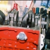
I was in the garage earlier and answered my own first question by looking at the back of some spare side clocks - the voltage regulator/stabiliser is on the back of the side dials at the bottom connected to/pushed into the printed circuit - in this case it has a B, I and E terminal


Attached File  Wire2.JPG   51.67K   1 downloads


The B and I  have the same function as a centre dial two terminal regulator and the E is in the earth part of the printed circuit so leads to a B-lack earth wire


If you have 12V to the printed circuit from the W-hite wire (do the ign and oil warning lights work?) then there should be 12v to the regulator unless the printed circuit is broken

If you have 12v at the B terminal you should then see 10v off the I terminal (to the fuel and temp gauges) if 12v at B but no 10v at I then the regulator is dead

If you have 10v at the regulator I terminal you should then find 10v at the GB G-reen & B-lack wire terminal - if no 10v then the gauge or printed circuit is broken

(You could also check for 10v at the GU G-reen & bl-U-e terminal from the temp gauge which might tell you something about the it being the printed circuit if no 10v at either)

If you have 10v at the wire terminal on the dials but not at the tank then the GB wire is broken somewhere in the loom

If you have 10v at the sender but no fuel gauge reading then the sender is bust or the earth off the sender is bad - you can check earth continuity easy enough to eliminate that


Hope this helps its just elimination


#13 mini-mad-mark

mini-mad-mark

    One Carb Or Two?

  • Members
  • PipPipPipPipPipPipPip
  • 703 posts
  • Local Club: northants wot no brakes

Posted 31 March 2020 - 06:27 PM

Sorry to be clear the switched 12v live is the W-hite wire (in this wire diagram anyway) from the ign switch (controls the ign and oil warning lights too)


0 user(s) are reading this topic

0 members, 0 guests, 0 anonymous users