Excuse the black maker pen but I have no engineers blue. The picture shows only a very small contact area. Should this cover the whole angled area?
 93119114-FE74-4307-B24B-5ECFDEDA365B.jpeg 80.33K
25 downloads
93119114-FE74-4307-B24B-5ECFDEDA365B.jpeg 80.33K
25 downloads

Speeding Along Now

Posted 30 May 2020 - 02:50 PM
93119114-FE74-4307-B24B-5ECFDEDA365B.jpeg 80.33K
25 downloads
Up Into Fourth

Posted 30 May 2020 - 03:08 PM
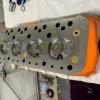
How much contact surface area should there be after a new valve has been installed and lapped?
Excuse the black maker pen but I have no engineers blue. The picture shows only a very small contact area. Should this cover the whole angled area?
93119114-FE74-4307-B24B-5ECFDEDA365B.jpeg
Camshaft & Stage Two Head

Posted 30 May 2020 - 03:51 PM
I was always led to believe that the exhaust valve needed full lap whilst the inlet only need a fine line lap. Is that still true?
Moved Into The Garage

Posted 30 May 2020 - 08:39 PM
For road use, you really want no less than 0.060" seat face contact for the exhausts.
Looking at that, I think you'll want to have the seats re-cut, then lap them.
Speeding Along Now
Posted 31 May 2020 - 07:49 AM
Thanks for the replies. Should it be the same contact area for the inlets valve and exhaust valves?
Looks like i will get busy with it today and see if i can improve the contact area, if not i will as advised get them re cut. They were supposed to already be done.
Moved Into The Garage
Posted 31 May 2020 - 08:40 AM
Again, for road use, yes, but you can happily go down to 0.040" on the Inlets.
The Exhausts need more to help disperse the heat out of the Valve Head.
Speeding Along Now
Posted 31 May 2020 - 08:46 AM
Up Into Fourth

Posted 31 May 2020 - 10:05 AM
Speeding Along Now
Posted 31 May 2020 - 10:15 AM
E7675D64-FE37-48DC-B788-87E45EF2EE22.jpeg 95.81K
12 downloads
Speeding Along Now
Posted 31 May 2020 - 10:19 AM
897A5B58-AA89-4935-A6A3-98C5A5FA7484.jpeg 85.6K
3 downloads
Up Into Fourth
Posted 31 May 2020 - 10:24 AM
Edited by Turbo Phil, 31 May 2020 - 10:26 AM.
Speeding Along Now
Posted 31 May 2020 - 10:32 AM
Speeding Along Now
Posted 31 May 2020 - 10:46 AM
45980717-4C60-4A30-9102-AFB56EF6952B.jpeg 65.74K
1 downloads
37E515CB-2075-4581-9BB6-7DC551F6F4F1.jpeg 90.43K
1 downloads
Up Into Fourth
Posted 31 May 2020 - 11:35 AM
Speeding Along Now
Posted 31 May 2020 - 02:23 PM
Thanks again for the info. Im learning a lot today. All valves now lapped and happy with contact area. The valves fitted look like they have been supplied from mini spares. The guides look standard cast iron type but maybe the exhaust enlarged to 8mm. As i have no idea what im doing here but would like to get it correct, what is the correct material used for the guides? I have done some reading and see other materials available. Is the standard cast guide ok for standard boost turbo engine? With the current valves that are fitted. Material not stated on mini spares.
Thanks
Rob


0 members, 1 guests, 0 anonymous users


