I have a splutter problem with my 98 MPi (had it about 6 weeks so still getting familiar with it)
It does start okay and idles around 750/850rpm (when warm) no problem, however, I do have the kangaroo symptoms at low revs/speeds, i.e. in traffic.
It has a full Maniflow exhaust system (with the knuckle joint) and all appears to be sealed and engine mounts/steadies etc. are all in good order.
On accelerating it runs great up to about 5,000/5,500 at which point it starts to splutter a bit with power dying off and if you try to just feather the throttle the splutter appears as if the mixture is wrong or fuel is being starved? A good boot of the throttle at any point and in any gear brings it back to life but this means I'm constantly accelerating/decelerating on a run (not good for fuel consumption!!).
I pulled the spark plugs today and they are NGK "Ridium" BKR7EIX although I see from a previous reply NGK BPR6ES are recommended? The ones fitted have a very thin centre electrode, are gapped to 0.025" and colour is a light brown (correct if I remember correctly?).
Just searched through the paperwork that came with the car and found an invoice/report for diagnosis of the same fault (obviously never fully cured?) with the following actions taken.........
- Lambda Sensor changed
- Spark Plugs changed
- Fuel Filter changed
- Fuel Pump Relay fitted (see below)
The above appears to have solved the initial problem as there was only 11.2v at pump and hesitation cured when supply to pump taken direct from the battery, thus relay fitted (is this additional to standard?)
- Thermostat changed
- ECU removed and sent for test = OK
- Wiring from ECU to Coil pack changed
This was all carried out in Aug 2007 and car only done 750 miles since then
ANY OTHER IDEAS FROM YOU MINI EXPERTS ???
PS - the diagnostics cost was £850 which I would rather not spend!!!!

Mpi Splutter!
Started by
nicksuth
, Dec 30 2007 06:29 PM
21 replies to this topic
#1

nicksuth
-
- Noobies
-

- 1,631 posts
Camshaft & Stage Two Head
- Location: Lutterworth
- Local Club: Rugby Classic Mini Owners Club
Posted 30 December 2007 - 06:29 PM
#2
DaveRob
-

- Members
-
- 703 posts
One Carb Or Two?
Posted 31 December 2007 - 08:59 AM
Just searched through the paperwork that came with the car and found an invoice/report for diagnosis of the same fault (obviously never fully cured?) with the following actions taken.........
- Lambda Sensor changed
- Spark Plugs changed
- Fuel Filter changed
- Fuel Pump Relay fitted (see below)
The above appears to have solved the initial problem as there was only 11.2v at pump and hesitation cured when supply to pump taken direct from the battery, thus relay fitted (is this additional to standard?)
- Thermostat changed
- ECU removed and sent for test = OK
- Wiring from ECU to Coil pack changed
PS - the diagnostics cost was £850 which I would rather not spend!!!!
I could be wrong here and shout out if any of you think so but maybe its the cynical side of me but £850 for diagnostics.....hmmmmm. Anyone with a diagnostic fault code reader would have been able to identify the correct operation of a Lambda sensor and would also be able to test the fuel pump relay, (and all the other relays). To have an ECU removed and sent for test seems a bit extreme as well.
Have you measured the voltage at the fuel pump, (engine running), and compared it to the battery voltage, mind you If the fuel pump can handle acceleration their is no reason to suggest that the pumps capacity is being impared by low voltage and for this reason as well I would suggest that the problem does not lie with the fuel filter. ECU to coil pack wiring must have been interesting to change as, (correct me if im wrong guys), the wiring terminates in the Econoseal connector and so would have had to be either bodged or some major loom replacement. Given the levels of diagnostics displayed by said supplier of service I doubt that the thermostat was changed so we are nearly at the end of your list and just about dismised all the things they changed......
Seriously though.... and on a much more positive note... lol Id check the MAP tubeing just to start with.... from the ECU end to start with. absolutly critical to have no kinks holes or leaks ANYWHERE as this causes more faults than any thing else. I had someone from this forum visit me to plug in my diagnostic tester and straight away MAP fault came up. cleared fault and MAP fault again so tubing checked and sure enough their was the fault. Just cause it says MAP sensor fault does not mean the sensor is at fault.... its how you read the code and assess the problem. Its also possible, given your description of the fault, that their may be an issue with the inlet air temperature sensor. My reasoning behind this is that you have no problem when you .. 'get your foot down'. The way that the injector system works is that the action of acceleration and deceleration are monitored through the throttle potentiometer. Movement of the throttle arm rotates the wiper arm in the pot. The ECU lengthens the injector open time when it detects a RISING voltage note here I say rising, ( other sensors are of course involved in the complex ECU map), HOWEVER when the throttle is fully open the ECU applies full load enrichment which is a fixed percentage and is INDEPENDANT OF TEMPERATURE ie the temp part of the ECU map is ignored. so maybe inlet air temp sensor is a possibility.
Im sure their are others going to advise...... maybe Sprocket will be along shortly, but you can have a look at the suggestions above. The easy way would be to find someone close with a Fault Code reader who knows how to use it. I do diags for free for our local injected minis but im a bit far from you.
Just my opinions tho.... as always.... do your own research
 lol.....
Tin hat on and ready to be shot at..
DaveRob
#3
nicksuth
-
- Noobies
-
- 1,631 posts
Camshaft & Stage Two Head
- Location: Lutterworth
- Local Club: Rugby Classic Mini Owners Club
Posted 31 December 2007 - 12:13 PM
Thanks for the detailed response, it is much appreciated, is there a simple test to check the air inlet temperature sensor? Oh, and what does it look like and where aboouts is it situated?
I do have a Multi-Meter kicking about somewhere if it's just checking resistance/voltage etc.
The garage that carried out the diagnostics did highlight 11.2v at Fuel Pump and fitted new relay which initially appeared to cure the hesitation (this was all done by a previous owner, I only have the report/invoice to work from - I am trying to contact him by email).
What's your thoughts on the NGK "Ridium" BKR7EIX plugs?
PS - The £850 did include all the parts and labour not just the diagnostics.
Nicksuth
#4
DaveRob
-
- Members
-
- 703 posts
One Carb Or Two?
Posted 31 December 2007 - 01:11 PM
The air temperature sensor, ATS on an MPi is mounted on the air inlet casing (I think... I have an SPi so mines on the filter casing). and measures the air temp before it enters the inlet manifold. The open circuit supply to the sensor from the ECU is 5 Volts ref and the earth path is through the sensor itself. It works on the neg temp coefficient principal, ( same as the coolant temp sensor) and when in circuit should provide the ECU with a signal of between 2 and 3 volts at an air temp of 20 degC reducing to 1.5 Volts at about 40 degC. I havnt done much checking on mine cause it works just fine but maybe if you put a volt meter on the sensor wire and the other meter probe to the manifold when the engine is up to temp you should get a reading of 2-3 volts at 20 degC ish ambient (might be nearer the 3 volts odd in the cold weather). without the fault code reader you cant be certain as that will show real time sensor interprted values.
Hope that helps a bit
DaveRob
Hope that helps a bit
DaveRob
#5
nicksuth
-
- Noobies
-
- 1,631 posts
Camshaft & Stage Two Head
- Location: Lutterworth
- Local Club: Rugby Classic Mini Owners Club
Posted 31 December 2007 - 02:10 PM
Someone else recommended changing the camshaft position sensor as this would restrict maximum revs if it is faulty or failed?
Any idea how expensive these bits are and if not too expensive is it worth changing them anyway?
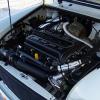
PS - I have attached a screen dump of the Engine Bay and Sensors, is this the MPi or SPi?

http://i213.photobuc...eBaySensors.jpg
http://i213.photobuc...uth/84dd_12.jpg
Who sells this type of stuff now, Minispares, Minisport etc.?
Cheers
Nicksuth
Any idea how expensive these bits are and if not too expensive is it worth changing them anyway?
PS - I have attached a screen dump of the Engine Bay and Sensors, is this the MPi or SPi?
http://i213.photobuc...eBaySensors.jpg
http://i213.photobuc...uth/84dd_12.jpg
Who sells this type of stuff now, Minispares, Minisport etc.?
Cheers
Nicksuth
#6
DaveRob
-
- Members
-
- 703 posts
One Carb Or Two?
Posted 31 December 2007 - 03:43 PM
The MPi and SPi are 2 different beasts and my knowlege of the MPi is limited so take this only as me passing on my limited knowlege of the Rover MEMS system.
These diagrames are from the MPi NOT the SPi although Ive never seen a cam sensor. The drawings and positions shown on your diagrams are all MPi models. As for the cam sensor being at fault Ill be honest and say I dont know a great deal about the sensor and Ill leave it to Sprocket to advise as to whether the engine would run without this working correctly. Rover MEMS has 2 MPi operational modes I dont know which one runs on the Mini MPi or if inded it runs both somehow. Their is a Sequential and simultaneous mode in MEMS. I thought the MPi Mini operated in simultaneos mode only..... I wait to be corrected on this one.... The Simultaneous mode needs a CRANK sensor and the sequential mode needs a CRANK sensor and a CAM sensor. My understanding of the CRANK sensor for what its worth, is that its an inductive sensor operating in conjunction with the flywheel . The flywheel is effectivly a reluctor ring. Their are 34 points spaced around the flywheel at 10 degree intervals that enable the inductive sensor to generate an output. As the flywheel spins an AC voltage is generated that indicates the speed of rotation. Their are 2 missing places in the flywheel that dont generate any output. They are 180 deg apart and 1 place is the TDC for pots 1 and 4 and the other is for TDC for pots 2 and 3. The PEAK TO PEAK voltage, ( not RMS), at idle should be of the order of 5 volts and rises to over 100V at 6000rpm. I belive that the resistance of this sensor should be in the range 1100 to 1700 ohms if you want to disconect it and try the multimeter on the terminals. The CAM sensor.....from the info I have is for cylinder ident and works off the cam shaft reluctor in a 4 segment mode.
By the way have you read all this post? http://www.theminifo...showtopic=62731
As much as I know is here, if its not 100% then im learning also......feel free to shout out anyone who knows different.
hope it helps
DaveRob
Edited by DaveRob, 31 December 2007 - 05:28 PM.
#7
elvisthepizzaman
-

- Members
-
- 161 posts
Mini Mad
- Local Club: Minis of the Rockies
Posted 31 December 2007 - 08:57 PM
unless the crank or cam sensors are broken by some physical force they generally last a long time. however, they are magnetic, so a large collection of metal bits on the end can affect the pulses.
#8
nicksuth
-
- Noobies
-
- 1,631 posts
Camshaft & Stage Two Head
- Location: Lutterworth
- Local Club: Rugby Classic Mini Owners Club
Posted 31 December 2007 - 09:58 PM
Thanks for all the feedback guys.
In order to dismiss any of these as the cause I have ordered a new camshaft position sensor and new air intake tempertaure sensor.
The exhaust will be checked over for leaks and sealed (following a meeting with a speed ratadrder this afternoon the other day bloody things!)
poo, I think there has been too many sensors and gadgets added to the mini since my last experience (980's), it was much more enjoyable when you could set the timing using a pair of marigolds and mixture by spark plug colour thn go out and *yellow human water* off a 3 litre Ford Capri down the bypass!!!!!!
Considering going back to basics and building a naturally aspirated version with split webbers or something?
Nicksuth
#9
swiss al
-

- Noobies
-
- 36 posts
On The Road
- Local Club: surry and london
Posted 01 January 2008 - 10:28 PM
all i can say is that i had all the same probs and as soon as i changed the cam sensor it was fine and touch wood a month later still is running great
#10
nicksuth
-
- Noobies
-
- 1,631 posts
Camshaft & Stage Two Head
- Location: Lutterworth
- Local Club: Rugby Classic Mini Owners Club
Posted 10 February 2008 - 12:02 PM
Changed th Camshaft Position Sensor but with no effect!!!!all i can say is that i had all the same probs and as soon as i changed the cam sensor it was fine and touch wood a month later still is running great
Ordered Air Temperature Sensor but out of stock currently at Mini Spares (on back order).
One thing I did take carful note of this time was when the "Splutter" started. Engine runs okay from starting cold and the splutter doesn't start until the engine is warm, would this suggest it is a sensor that monitors/reacts to temperature rise (i.e. the ATS)?
Splutter is caused by a hesitation for the engine to react to light acceleration or trying to "feather" the throttle (i.e. when motorway driving), it can be overcome by "booting" the throttle everytime but I guess that ain't gonna do my mpg any good.
Anyone got any ideas or do you thing this points specifically to the ATS???
#11
elvisthepizzaman
-
- Members
-
- 161 posts
Mini Mad
- Local Club: Minis of the Rockies
Posted 10 February 2008 - 07:10 PM
The kangarooing is a byproduct of the idle stepper motor opening up to let in emmission gasses. The ecu only does this when the motor has reached operating temp. You feel it the most during light throttle as the stepper motor has to keep opening and closing up with reaction to your demand. When you mash down on the throttle the ecu goes from econonmy fueling to its max fueling programming to achieve the acceleration you demanded. If the stepper motor gets gummed up with the oily gasses it may not seal properly or move properly on command from the ecu.
I have an idea: What is the coolant fan doing, is it running from startup or does it come on when its supposed to? what are your cold starts like? I would give your coolant temp sensor a good cleaning (both halfs) with electrical contact cleaner (spray can) then take your idle stepper motor out and throughly spray the inners of it. I was having a problem with my idle stepper motor and my cold starts were hard and I had the kangaroo effect you described, but once I throughly cleaned both coolant temp and the idle motor itself everything went away. I had to spray alot of cleaning solution into the motor housing with lots of shaking to get it really clean.
I have an idea: What is the coolant fan doing, is it running from startup or does it come on when its supposed to? what are your cold starts like? I would give your coolant temp sensor a good cleaning (both halfs) with electrical contact cleaner (spray can) then take your idle stepper motor out and throughly spray the inners of it. I was having a problem with my idle stepper motor and my cold starts were hard and I had the kangaroo effect you described, but once I throughly cleaned both coolant temp and the idle motor itself everything went away. I had to spray alot of cleaning solution into the motor housing with lots of shaking to get it really clean.
Edited by elvisthepizzaman, 10 February 2008 - 07:17 PM.
#12
Sprocket
-
- Members
-
- 7,266 posts
Great on Injection faults
- Location: Warrington
- Local Club: Manchester Minis
Posted 10 February 2008 - 08:58 PM
Neaver heard anything more non relative to the Mini injection systems than that.
The IACV (Idle Air Control Valve) function is to control the idle speed and NOTHING else
The problem could be the MAP sensor or the throttle psoition sensor.
As you accelerate, depending on how fast, there needs to be an addition of fuel to overcome the saturation of the manifold with air causing lean condition at least untill the lambda sensor picks it up. This is called acceleration enrichment, and is a factor of how fast you open the throttle. The ecu monitors the throttle position sensor for rate of change. if this is not functioning correctly, the acceleration enrichments will be all wrong and hesitaion evident, but only for a short period.
An other possability is the MAP sensor, for what ever reason, not reacting to small changes in manifold pressure, this does two things. The ECU will not provide enough fuel and the ignition advance will be all wrong, this would be of a more persistant hesitation.
Without having a code reader connected to monitor the variables and going for a drive to generate the condition, its going to be a matter of replacing parts. If you do this, make sure you refit the old part if it is found not to be the problem and keep the new item as a spare or return it.
#13
elvisthepizzaman
-
- Members
-
- 161 posts
Mini Mad
- Local Club: Minis of the Rockies
Posted 10 February 2008 - 09:11 PM
D'oh!...  my knowledge has been corrected once again by the all knowing Sprocket.. .So how does all that black goo stuff get into the stepper motor?? and why did cleaning both the coolant temp sensor contacts and the motor fix my kangarooing problem??
my knowledge has been corrected once again by the all knowing Sprocket.. .So how does all that black goo stuff get into the stepper motor?? and why did cleaning both the coolant temp sensor contacts and the motor fix my kangarooing problem??
Edited by elvisthepizzaman, 10 February 2008 - 09:17 PM.
#14
ICAM
-

- Noobies
-
- 53 posts
Stage One Kit Fitted
- Local Club: smoc
Posted 11 February 2008 - 10:39 AM
'Engine runs okay from starting cold and the splutter doesn't start until the engine is warm'
Dear Nick,
Care to explain further this symptom. You mention engine run ok but doesn't start until the engine warm?
Dear Nick,
Care to explain further this symptom. You mention engine run ok but doesn't start until the engine warm?
#15
nicksuth
-
- Noobies
-
- 1,631 posts
Camshaft & Stage Two Head
- Location: Lutterworth
- Local Club: Rugby Classic Mini Owners Club
Posted 11 February 2008 - 09:12 PM
Car starts from cold every time, no problem, runs at elevated revs (function of ECU acting like a choke I guess?) for about 5 mins and as soon as it is warm, revs drop back and engine ticks over no problem. On driving away (i.e. engine under load) and engine still only "warmish" it runs without missing a beat but as soon as it has run for about 15-20 minutes (up to operating temperature?) the hesitation starts. While progressively pressing the throttle their is a hesitation to pick up which does not clear until I press pedal to the floor! Hesitation and Splutter is evident also when trying to "feather" the throttle, i.e. when motorway/dual carriageway driving.
Electric fan is cutting in and out at what seems to be the right time, it certainly takes 1 good 15 minutes or so before cutting in when stood ticking over.
Also, (see previous posts) there was a full diagnostic checkover with several parts changed only 900 miles ago.
Not sure what more I can say?
Engine is coming out soon for gearbox rebuild at which time it will get a thorough clean and checkover.


0 user(s) are reading this topic
0 members, 0 guests, 0 anonymous users


