

Going For The Magic Number...
Started by
DaveRob
, Apr 13 2008 06:11 PM
69 replies to this topic
#16

Sprocket
-
- Members
-

- 7,266 posts
Great on Injection faults
- Location: Warrington
- Local Club: Manchester Minis
Posted 14 November 2008 - 09:07 PM
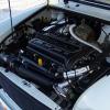
Look No holes
#17
Bungle
-

- Members
-
- 28,971 posts
Original Spamster
- Location: Cornwall
- Local Club: cornish mini club
Posted 14 November 2008 - 09:11 PM
it think but someone is lightly to correct me 
instead of water from the block going through little holes through the head gasket into the head, the head and block water passages are blocked up and a external pipe is used to go from block to head to carry the water
reason is the head gasket is less lightly to go
instead of water from the block going through little holes through the head gasket into the head, the head and block water passages are blocked up and a external pipe is used to go from block to head to carry the water
reason is the head gasket is less lightly to go
#18
DaveRob
-
- Members
-
- 703 posts
One Carb Or Two?
Posted 15 November 2008 - 08:09 AM
Dry Deck is not only waterways but also the oilway so basically like Sprocket says the only holesyou see in the block and head are the pushrod holes....... This eliminates all the water and oil from t5he interface between the block and deck so making for a more reliable setup. The waterways are routed from the front left core plug of the block, which I have removed..... up to a machined spigot I have made, that plugs into a hole in the end of my cylinder head, that I have machined lol..... the oil is routed from the front of the block to the back of the head where their is a brass plug that I have removed and replaced with a banjo fitting up to the back of the head..... Their are some 'dry deck'kits. but when you look at them they appear to be a head gasket with no waterway holes made in steel........ In my opinion this isnt why or how a dry deck works.....
Hope this helps
Rob
Hope this helps
Rob
#19
edi57
-

- Members
-
- 821 posts
One Carb Or Two?
Posted 15 November 2008 - 07:28 PM
Hmm that's really interesting stuff, thanks for explaining it!
I look forward to seeing lots of pics of your engine to show off all this good work!
I look forward to seeing lots of pics of your engine to show off all this good work!
#20
SMP
-

- Members
-
- 346 posts
Speeding Along Now
Posted 16 November 2008 - 08:52 PM
Thanks for the explanation.
So the water can flow through through the thermostat - OK follow that bit.
How does the oil return to the sump - do you leave those holes open?
I presume sockets block was a BMW conversion as there were no pushrod holes?
Also do you plug the corresponding holes in the head - otherwise you still have water pressure at the cylinder head gasket?
Steve
#21
DaveRob
-
- Members
-
- 703 posts
One Carb Or Two?
Posted 17 November 2008 - 09:14 AM
Oil returns to the sump through the pushrod holes..... Sprockets pictre is indeed of a BMW head conversion. Yes both the block and the head are plugged. Ive used brass taper plugs and machined them flush to the head and block after installation.n Water flow is through the block to the front left core plug ( as you look at the engine in the car ) where it exits through a spigot that is made to fit the core plug hole then through a U shaped silicon hose to the head where another spigot is fitted to the head. The head has to have a flat machined on then a hole is machined to take the spigot.... Water flow is then straight through the head to the thermostat....
Hope this helps
Rob
Hope this helps
Rob
#22
DaveRob
-
- Members
-
- 703 posts
One Carb Or Two?
Posted 09 February 2009 - 07:42 PM
ok along with some photos heres a bit of an update on the machining Ive done over the last few weeks.
Take 1 stripped block... Offset bore to 73.5mm and hone....tap all the water and oil galleries and fit taper plugs in brass... dry assenble all the piston rod and crank and measure the top of piston to deck height. Buret the head and work out how much to skim from the deck to get 11:1 comp ration. In my case its 0.76mm. I fitted taper plugs to all the water and oil galleries and also tapped the end oil galleries as well as the little one under the pressure relief valve. So with all the oil and water galleries pluged Ive then made 2 aluminium spigots to carry the water from the front left core plug to the head. The head has been spot faced to 51mm then bored to take the spigot.
The oil to the rockers will go from a Tee on the oil pressure switch to the back of the head behind the thermostat where their is brass plug thats been removed and a fitting will be screwed in to accept the braided oil line feed.
That makes for a complete DRY DECK
The center main strap has been flash ground to ensure flatness and the main cap milled then flashed to ensure an almost 'wring' finish
Photos....
 IMAG0022.jpg 539.65K
230 downloads
IMAG0022.jpg 539.65K
230 downloads
IMAG0025.jpg 519.16K
211 downloads
IMAG0026.jpg 560.82K
193 downloads
IMAG0027.jpg 505.05K
179 downloads
IMAG0033.jpg 449.75K
190 downloads
IMAG0034.jpg 515.45K
187 downloads
DSCF1416.JPG 604.6K
94 downloads
DSCF1417.JPG 611.61K
85 downloads
DSCF1418.JPG 612.77K
202 downloads
DSCF1419.JPG 615.51K
235 downloads
DSCF1420.JPG 611.79K
40 downloads
I finally feel that its starting to come to the point where I can put it all back together now.... Evenings this week will be cleaning every last nook and cranny. 24 hrs soak in Diesel then srub up with Jizer, then the scrub up somemore. Completly degrease the surfaces to be painted then I should get it painted this weekend. Full assembly starts next week.
As always Kudos to Sprocket....
Rob
Take 1 stripped block... Offset bore to 73.5mm and hone....tap all the water and oil galleries and fit taper plugs in brass... dry assenble all the piston rod and crank and measure the top of piston to deck height. Buret the head and work out how much to skim from the deck to get 11:1 comp ration. In my case its 0.76mm. I fitted taper plugs to all the water and oil galleries and also tapped the end oil galleries as well as the little one under the pressure relief valve. So with all the oil and water galleries pluged Ive then made 2 aluminium spigots to carry the water from the front left core plug to the head. The head has been spot faced to 51mm then bored to take the spigot.
The oil to the rockers will go from a Tee on the oil pressure switch to the back of the head behind the thermostat where their is brass plug thats been removed and a fitting will be screwed in to accept the braided oil line feed.
That makes for a complete DRY DECK
The center main strap has been flash ground to ensure flatness and the main cap milled then flashed to ensure an almost 'wring' finish
Photos....
IMAG0022.jpg 539.65K
230 downloads
IMAG0025.jpg 519.16K
211 downloads
IMAG0026.jpg 560.82K
193 downloads
IMAG0027.jpg 505.05K
179 downloads
IMAG0033.jpg 449.75K
190 downloads
IMAG0034.jpg 515.45K
187 downloads
DSCF1416.JPG 604.6K
94 downloads
DSCF1417.JPG 611.61K
85 downloads
DSCF1418.JPG 612.77K
202 downloads
DSCF1419.JPG 615.51K
235 downloads
DSCF1420.JPG 611.79K
40 downloadsI finally feel that its starting to come to the point where I can put it all back together now.... Evenings this week will be cleaning every last nook and cranny. 24 hrs soak in Diesel then srub up with Jizer, then the scrub up somemore. Completly degrease the surfaces to be painted then I should get it painted this weekend. Full assembly starts next week.
As always Kudos to Sprocket....
Rob
#23
kitroxin
-

- Traders
-
- 494 posts
Speeding Along Now
- Local Club: Celtic Minis
Posted 12 February 2009 - 10:59 AM
Hello, just a quick word of warning about the SC manifold, i bought one and was very impressed by the shiny'ness, however the downpipes point different directions and even if i force them into the Y-piece one keeps popping out, I extended the Lambada wireing in order for it to reach the Y-piece also which was a bit of a faff.
Although from what you have already done putting this right will probably be small fry to you!
I personally am going down the maniflow route as soon as i can afford another one, you are welcome to make me an offer for my SC if you think you can make it work for you.
Cheers, kit
Although from what you have already done putting this right will probably be small fry to you!
I personally am going down the maniflow route as soon as i can afford another one, you are welcome to make me an offer for my SC if you think you can make it work for you.
Cheers, kit
#24
kitroxin
-
- Traders
-
- 494 posts
Speeding Along Now
- Local Club: Celtic Minis
Posted 12 February 2009 - 11:02 AM
OH and by the way, good luck getting 100bhp, will be a monster!!!
i have a stage 3 head on my spi and a few other cheeky mods, and even that scares me sometimes!
i have a stage 3 head on my spi and a few other cheeky mods, and even that scares me sometimes!
#25
rozzer1275
-

- Members
-
- 439 posts
Speeding Along Now
- Local Club: ah
Posted 13 February 2009 - 12:40 PM
looking good keep the updates coming
#26
dbcool20
-
- Noobies
-
- 91 posts
Stage One Kit Fitted
Posted 18 February 2009 - 08:41 PM
Great work, looks really good. Hey what mods can be done on the throttle body? I'am also currnently in the mood for HP on my spi mini
#27
revingtosh
-

- Members
-
- 178 posts
Mini Mad
Posted 07 March 2009 - 12:18 PM
Great work, looks really good. Hey what mods can be done on the throttle body? I'am also currnently in the mood for HP on my spi mini
Can i ask what engine stand you are using for this build? How much it cost, and where it come from/
I need one that bolts to the alternator mounts like yours, rather than at the gearbox end.
Cheers,
Mike
#28
Sprocket
-
- Members
-
- 7,266 posts
Great on Injection faults
- Location: Warrington
- Local Club: Manchester Minis
Posted 07 March 2009 - 01:25 PM
Thats just the ordinary Clarke engine stand available from any Machine Mart The mounting adapater has been cut down and extra holes drilled to mount the block
The mounting adapater has been cut down and extra holes drilled to mount the block
#29
DaveRob
-
- Members
-
- 703 posts
One Carb Or Two?
Posted 08 March 2009 - 09:07 AM
As Sprocket says that is just the standard Machine mart stand.... sooooo cheap lol..... chuck away the 4 mounts and the bolts. Then measure up your oil filter spacing and the bottom alternator bracket hole... make sure its VERY accurate. cut the clarke engine stand bracket to suit, have a look at the pic of the block being machined above to get the general idea........ BECAREFUL.... the tube can get close to the drilling points if you dont space it out right on the bracket. The oil filter holes are 3/8th UNC the alternator is 5/16 unf...... Get suitable sized bolts, make sure the oil filter ones dont protrude into the block or you will have trouble fitting one of the conrods as anything sticking into the block fouls the rod on rotation, then fit bracket with a suitable spacer under at the alternator fixing hole so you done induce bending forces. always best to clean out the holes first with a same size tap..... and away you go..... makes it soooooooooo easy to work on.
Rob
Rob
#30
Saxo-Fiesta-Mini
-

- Members
-
- 2,889 posts
Up Into Fourth
- Local Club: LCMOC
Posted 08 March 2009 - 09:16 AM
thats a proper job look forward to seein this done


0 user(s) are reading this topic
0 members, 0 guests, 0 anonymous users


