Well this is a bit of an extra thread as Mini Mad Me has already done a Megajolt thread but i thought i would do my own as i built my unit from the kit(rather than cheating!!)
so as and when i can be bothereed to sit and sort the photo's out i will add a bit of narrative and some funky photo's.


MegaJolt Map sensor kit build up
Started by
miniboo
, Aug 09 2007 12:58 AM
16 replies to this topic
#2

miniboo
-
- Members
-

- 9,327 posts
Lord of Original Thinking
Posted 09 August 2007 - 05:21 AM
so here are a few pics of the kit in all its little packets. and one of the case to show the actual size of it.


#3
miniboo
-
- Members
-
- 9,327 posts
Lord of Original Thinking
Posted 09 August 2007 - 05:29 AM
more to come tomorrow when i figure out how to upload lots of pics to imageshack in a oner.
#4
miniboo
-
- Members
-
- 9,327 posts
Lord of Original Thinking
Posted 12 August 2007 - 03:08 AM
more pics of the soldering in progress and also of the pc i picked up from someones rubbish pile that they left out for the bin men. fter getting a bargain laptop on ebay i couldnt get it to work so when i saw this i thought why not. so now i have proved it works all i need to do now is make up a wiring loom out of the bargain EDIS setup i got. Also need to do pics of that aswell


#5
Ethel
-

- TMF Team
-
- 26,154 posts
..is NOT a girl!
- Local Club: none
Posted 12 August 2007 - 08:16 AM
I've more or less completed mine too.
I'd recommend the kit as it's so well put together a trained monkey could assemble it. I can safely say that 'because I'm an untrained monkey 'n I managed - least I think I did, waiting on a usb adapter to fire it up.
I can add a few snaps of my homespun sensor bits to throw a few ideas up for anyone who's interested.
#6
Phaeton
-

- Members
-
- 1,055 posts
One Carb Or Two?
Posted 12 August 2007 - 09:35 AM
Just be careful on the chipset of the USB adaptor, it doesn't like some of them, you need to have a look on the autolabs website, there's quite a long thread about it.waiting on a usb adapter to fire it up.
Alan,...
EDIT Website is http://www.autosportlabs.net
Edited by Phaeton, 12 August 2007 - 05:24 PM.
#7
8vAlan
-

- Members
-
- 426 posts
Speeding Along Now
- Local Club: NENE Valley
Posted 12 August 2007 - 09:49 AM
hello, im fairly new to the megajolt concept, and have a couple of questions...
1)what is the price of this kit? and...
2)will it work with my c16se?
cheers
1)what is the price of this kit? and...
2)will it work with my c16se?
cheers
#8
Ethel
-
- TMF Team
-
- 26,154 posts
..is NOT a girl!
- Local Club: none
Posted 12 August 2007 - 10:03 AM
Cheers Phaeton,
I may have to read that, I'd probably of assumed I'd toasted or zapped the chips
I just bought a cheapy off Ebay. hope there's no risk of zapping the 'jolt through it?
AD, Autosport Labs have a huge forum/site on Megajolt.
Basically it's a fully programmable controller that lets you use Ford Edis ignition on any engine you can fix the Ford timing wheel (36-1 teeth) and sensor to.
Ideal for any non injection lump.
#9
Ethel
-
- TMF Team
-
- 26,154 posts
..is NOT a girl!
- Local Club: none
Posted 12 August 2007 - 10:07 AM
Price....
Hope to have mine up and running for just under £100 all in. Shouldn't cost over £250 for an A series even if you bought everything off the shelf. It's just the trigger you'd have to sort differently.
Hope to have mine up and running for just under £100 all in. Shouldn't cost over £250 for an A series even if you bought everything off the shelf. It's just the trigger you'd have to sort differently.
#10
miniboo
-
- Members
-
- 9,327 posts
Lord of Original Thinking
Posted 12 August 2007 - 04:17 PM
had a play with my laptop last night(reinstalled windows) and i have managed to get iot working which is great because i can now do in car tuning!!!

connected to 9v dc battery for testing

Laptop on and working well chuffed
now to start the wiring lom, not sure where to start yet though lol

connected to 9v dc battery for testing

Laptop on and working well chuffed
now to start the wiring lom, not sure where to start yet though lol
#11
miniboo
-
- Members
-
- 9,327 posts
Lord of Original Thinking
Posted 12 August 2007 - 07:13 PM

here is what i started with. I managed to get this for a bargain on ebay with a hell of a lot of loom aswell.

This is what i have ended up wuth after stripping it down

here is all the xtra carp i was left with. will keep it for now just in case i need to lengthen any wires at all
#12
Ethel
-
- TMF Team
-
- 26,154 posts
..is NOT a girl!
- Local Club: none
Posted 12 August 2007 - 10:08 PM
More piccies to bore you with 
Coil pack:
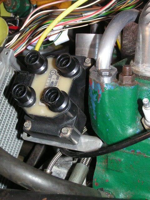
Edis Coil pack mounted on a couple of doody ally brackets as it's getting rather full under my bonnet. Front one is on the front steady bar bolt hole (no steady bar being used so it was going spare) rear one just slots over the oil separator. Good air circulation, high enough to stay dry (I hope) and nice and accessible.
Trigger wheel and crank sensor
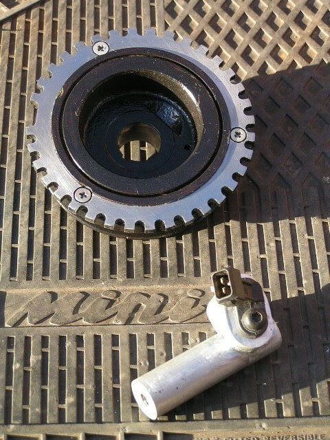
Turned down crank damper with a 5 1/8" triggerwheels.com erm, trigger wheel
I'm quite chuffed that it's within 25 grammes of what it was before I stuck it on a lathe - the wheel is 5mm thick but I took about 6mm off the pulley to compensate for the teeth. Luckily the missing tooth is pretty close to where a balancing drilling was in the damper but I still measured up the holes I machined off and added some afterwards in an attempt to not disturb things too much. The new holes aren't big, you can't see them because they're behind the wheel. The damper counter weight is cast iron 'n not mild steel as I think I'd read somewhere. A golden shower (of sparks!) before I turned the cutting speed down told me. I also found out that the rubber bonding is pretty tough when I stalled the lathe adjusting the cross feed indexing with the chuck still spinning 'n so didn't notice the tool taking a nice big bite on the pulley  . It did spin the shank of the pulley in the chuck so beware if you want your oil seal to have a chance, fortunately it wouldn't matter with my belt drive cam anyway.
Those screws are 5mm x16mm which have gone in very well for length, no sign of breaking through the other side, but you'll notice you wouldn't want the heads any bigger at all! 4mm might be a safer bet.
Quick tip: even if you pay someone to machine a pulley for you get them to score a circle as a centre line for the screw holes on the tooth wheel at the very least (much easier with a lathe). You'll probably want to fix the wheel on yourself once you've worked out where the sensor is going and the only way you'll get the screw holes to line up is to drill the trigger wheel and damper together.
The shiny thing at the bottom is the mounting for the crank sensor, two bits of 20mm bar (one round, one square) joined together with a bit of 8mm threaded rod. The sensor is somewhere between 13 and 14mm in diameter just to be awkward when you're making a hole for it. Another 8mm thick slice of aluminium is soldered on top to get the right clearance off the trigger wheel.
Fitted to Lump
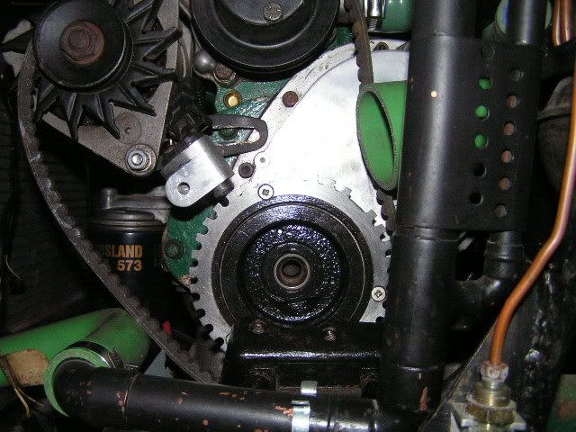
I think that's tidy by my standards the sensor bracket is bolted through an existing hole in the endplate that just happened to be kicking around thanks to the belt setup. My cunning plan was to thread the sensor's wiring between the alternator and the engine so I can do things like change a fan belt without having to disturb it. I also took the angle grinder to the radiator bracket so I can thread a belt in easily and put a socket on the pulley bolt. If you're thinking you get nice access without any inner wings you'd be right but I've two intercooler and an air intake hose to squeeze in there without the trigger wheel acting like a circular saw on them - I love a challenge me 
Coil pack:
Edis Coil pack mounted on a couple of doody ally brackets as it's getting rather full under my bonnet. Front one is on the front steady bar bolt hole (no steady bar being used so it was going spare) rear one just slots over the oil separator. Good air circulation, high enough to stay dry (I hope) and nice and accessible.
Trigger wheel and crank sensor
Turned down crank damper with a 5 1/8" triggerwheels.com erm, trigger wheel
I'm quite chuffed that it's within 25 grammes of what it was before I stuck it on a lathe - the wheel is 5mm thick but I took about 6mm off the pulley to compensate for the teeth. Luckily the missing tooth is pretty close to where a balancing drilling was in the damper but I still measured up the holes I machined off and added some afterwards in an attempt to not disturb things too much. The new holes aren't big, you can't see them because they're behind the wheel. The damper counter weight is cast iron 'n not mild steel as I think I'd read somewhere. A golden shower (of sparks!) before I turned the cutting speed down told me
. I also found out that the rubber bonding is pretty tough when I stalled the lathe adjusting the cross feed indexing with the chuck still spinning 'n so didn't notice the tool taking a nice big bite on the pulley . It did spin the shank of the pulley in the chuck so beware if you want your oil seal to have a chance, fortunately it wouldn't matter with my belt drive cam anyway.Those screws are 5mm x16mm which have gone in very well for length, no sign of breaking through the other side, but you'll notice you wouldn't want the heads any bigger at all! 4mm might be a safer bet.
Quick tip: even if you pay someone to machine a pulley for you get them to score a circle as a centre line for the screw holes on the tooth wheel at the very least (much easier with a lathe). You'll probably want to fix the wheel on yourself once you've worked out where the sensor is going and the only way you'll get the screw holes to line up is to drill the trigger wheel and damper together.
The shiny thing at the bottom is the mounting for the crank sensor, two bits of 20mm bar (one round, one square) joined together with a bit of 8mm threaded rod. The sensor is somewhere between 13 and 14mm in diameter just to be awkward when you're making a hole for it. Another 8mm thick slice of aluminium is soldered on top to get the right clearance off the trigger wheel.
Fitted to Lump
I think that's tidy by my standards
the sensor bracket is bolted through an existing hole in the endplate that just happened to be kicking around thanks to the belt setup. My cunning plan was to thread the sensor's wiring between the alternator and the engine so I can do things like change a fan belt without having to disturb it. I also took the angle grinder to the radiator bracket so I can thread a belt in easily and put a socket on the pulley bolt. If you're thinking you get nice access without any inner wings you'd be right but I've two intercooler and an air intake hose to squeeze in there without the trigger wheel acting like a circular saw on them - I love a challenge me
Edited by Ethel, 13 August 2007 - 05:30 PM.
#13
Tomm
-

- Members
-
- 2,462 posts
Up Into Fourth
- Location: Rochester, Kent
Posted 13 August 2007 - 01:20 PM
Sorry for my ignorance but i have read about Meagjolt a lot before on various other forums, had a look on thier website and it all just flew over my head. What actualy is it? Some thing to do with engine management or some thing?
Sorry Boo!
Sorry Boo!
#14
miniboo
-
- Members
-
- 9,327 posts
Lord of Original Thinking
Posted 13 August 2007 - 02:08 PM
no no thats fine.
basically it replaces your distributor witha boc of electronics. it also uses ford igniotion parts to sense the crank position and then fir the coil which produces the spark.
have a read of the FAQ that mini mad me has done.
basically it replaces your distributor witha boc of electronics. it also uses ford igniotion parts to sense the crank position and then fir the coil which produces the spark.
have a read of the FAQ that mini mad me has done.
#15
The Matt
-

- Admin
-
- 17,232 posts
You don't escape that easily.....
- Name: Matt
- Location: Overton, North Wales
- Local Club: Welsh Border Minis
Posted 13 August 2007 - 02:11 PM
Interesting schtuff Boo! 


0 user(s) are reading this topic
0 members, 0 guests, 0 anonymous users


