Jump to content


Photo

Little Less Conversation A Little More........


  • Please log in to reply
246 replies to this topic

#16 SukiDawg

SukiDawg

    Speeding Along Now

  • Members
  • PipPipPipPipPip
  • 304 posts

Posted 21 May 2009 - 05:56 AM

Got a little more done recently..

Posted Image

Posted Image

Edited by SukiDawg, 21 May 2009 - 05:59 AM.


#17 lchris21

lchris21

    Mini Mad

  • TMF+ Member
  • PipPipPipPip
  • 106 posts

Posted 21 May 2009 - 06:12 AM

Looking good !

#18 The Matt

The Matt

    You don't escape that easily.....

  • Admin
  • PipPipPipPipPipPipPipPipPipPipPip
  • 17,229 posts
  • Name: Matt
  • Location: Overton, North Wales
  • Local Club: Welsh Border Minis

Posted 27 May 2009 - 07:11 AM

Still trying to get my head around how you're doing this at the moment.

The propshaft is going to run inside the car? Then you'll be chopping through the rear seat/heelboard to mate with the rear diff?

#19 SukiDawg

SukiDawg

    Speeding Along Now

  • Members
  • PipPipPipPipPip
  • 304 posts

Posted 27 May 2009 - 10:47 AM

Not quite, I defintely would not want a proshaft which had just failed one of its joints flayling about in the same space as my soft fleshy body...!! There will be a tunnel for the prop to run through strong enough to restrain the propshaft should such an event take place - I just haven't detailed it as yet.

When you are doing a whole car like this you lay out the important things first such as engine position, diff position yada yada.. Then the connecting parts such as a the prop, and hopefully then you fit the structure around it. Right now I am still very much at that stage of fitting the important parts together, and so it looks like the prop runs through the cabin... The shell model is of a standard shell because thats what I have to start with in the real world....

The next stage (and what I'm working on now) is to model the front subframe so I can tie down the engine position along with front suspension components, front bodywork etc. I will start with a model of a standard one, to position everything, and then either modify that or design a totally new one as required to suit the new engine.

I can't really do the tunnel until the exhaust system size is fixed, and I've routed it. The high sprocket position of the R1 engine (relative to the bottom of the sump) does tend to leave the propshaft high at the front - bad for C.O.G., but does enable me to possibly run the exhuast below the propshaft at least until it is past the seats. Then and only then can I detail the cabin properly.

#20 daveeeeee

daveeeeee

    Super Mini Mad

  • Members
  • PipPipPipPipPipPip
  • 684 posts

Posted 01 June 2009 - 10:11 PM

Subscribed! Really interested to see how it works out mocking it up on the PC, most people just chop! Nice work.

#21 cptkirk

cptkirk

    Camshaft & Stage Two Head

  • Members
  • PipPipPipPipPipPipPipPip
  • 1,799 posts
  • Location: West Sussex
  • Local Club: B.M.C. + Chiminiclub

Posted 02 June 2009 - 08:24 AM

Whats the theory behind the Freelander diff? Ease of purchase or something more sinister/interesting?

Oh and I have subscribed also to keep up with all the developments.

>_<

#22 SukiDawg

SukiDawg

    Speeding Along Now

  • Members
  • PipPipPipPipPip
  • 304 posts

Posted 02 June 2009 - 09:15 AM

The freelander diff really is taking over from the sierra one for BEC convertions now. Yes, as you say, there are a lot more of them about - but also the suitable ratios from Sierras are getting harder and harder to find (you need a diesel sierra iirc) and also they weigh a bit more. A freelander diff is 17Kg and I think a Sierra one is 21Kg or something like that.

The mount bosses on the freelander unit are not quite as suitable as the sierra but apart from that they just seem a better prospect. All the kit car boys are on them now..


Looking at ratio, the freelander unit is 3.182 : 1 and the Sierra unit (most commonly available) is 2.88:1. If you work through the gearing it gives me 123mph in 6th at 14krpm for the freelander unit and 136mph for the Sierra. I don't really want to get too involved with mini aerodynamics at 120 never mind 136mph!

Thanks for the subscriptions, I'll try and keep somekind of regular update coming. I am dying to start out in the workshop I tell you, but must resist until its time!

#23 cptkirk

cptkirk

    Camshaft & Stage Two Head

  • Members
  • PipPipPipPipPipPipPipPip
  • 1,799 posts
  • Location: West Sussex
  • Local Club: B.M.C. + Chiminiclub

Posted 02 June 2009 - 09:19 AM

Ah I see, thanks for the info, I'll bear that in mind for future use.

#24 SukiDawg

SukiDawg

    Speeding Along Now

  • Members
  • PipPipPipPipPip
  • 304 posts

Posted 05 June 2009 - 06:49 PM

Beginnings of the standard front subframe in this week...

Posted Image

#25 daveeeeee

daveeeeee

    Super Mini Mad

  • Members
  • PipPipPipPipPipPip
  • 684 posts

Posted 05 June 2009 - 10:41 PM

Looks good, are you going to keep most of the original subframe, or are you just drawing it for dimensions?

With the weight of the engine all on the nearside, how are you going to balance it out? Just interested!

Dave

#26 Saxo-Fiesta-Mini

Saxo-Fiesta-Mini

    Up Into Fourth

  • Members
  • PipPipPipPipPipPipPipPipPip
  • 2,889 posts
  • Local Club: LCMOC

Posted 06 June 2009 - 02:31 AM

great work cant wait to be learning CAD design as part of my engineering degree gonna plan out my wankle engine design and get it all plan out b4 i even think about cutting the car with a plasma cutter as i know i want my design to be spot on

#27 sotiris

sotiris

    Mini Mad

  • Noobies
  • PipPipPipPip
  • 127 posts

Posted 06 June 2009 - 06:29 AM

good luck..

prof. job............

#28 SukiDawg

SukiDawg

    Speeding Along Now

  • Members
  • PipPipPipPipPip
  • 304 posts

Posted 09 June 2009 - 07:59 PM

A productive few days.. Laid in a lot of bits and pieces..

Posted Image

Posted Image

#29 SukiDawg

SukiDawg

    Speeding Along Now

  • Members
  • PipPipPipPipPip
  • 304 posts

Posted 20 June 2009 - 04:57 PM

Hmmm no replies since last time when I had the turbo visible for the first time - thought someone would have noticed!!

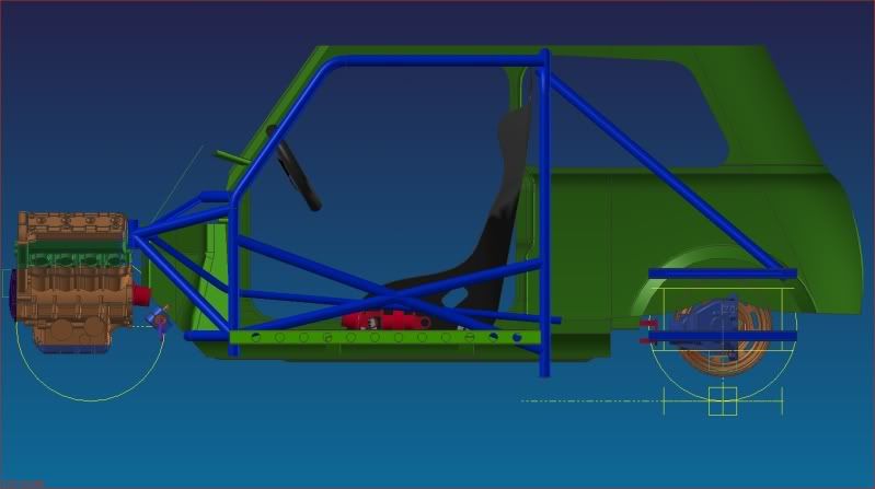
Anyway, I have been busy again this week, and I reckon the thing is starting to look like a car now. I have some concern over the rollcage weight though. According to the computer, at the moment I am just shy of 70Kg for the added structure. Seems a bit heavy to me, but at the same time I have gone a little bananas with it in places (trans tunnel for one) so there is the possibility of removing some weight there perhaps. I am working on a spreadsheet with all the component masses etc and their locations on the car to give me a theoretical final weight, COG height and weight distribution so when thats a bit more advanced it might be time to get the axe out and try to take some weight out of the design. Its not been possible to fully populate this spreadsheet up until now because I didn't really know enough information, but thats changing as I design bits and decide whats what.

One good thing - I finally found out an all up steel body weight - with boot, bonnet and doors the body weighs 155Kg apparently. I now need to weigh the door and front panel I still have off the red mini and the bonnet / boot to get an idea of the total monocoque weight. I'll guess what the wings weigh... With that done I'll know how close to my target I am (in theory). I guessed about 70Kg a while ago, and I might not have been too far off, perhaps a little under.

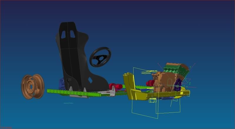
This week started out with the engine installation - trying to tie that down properly, and I then moved onto the rear suspension design and the structure required for the pick up points. Exhaust fits front to back, and the exhaust manifold clears the suspension tower of the standard subframe (JUST!). I know where the intercooler is going, and how I'm going to plumb to it from the turbo. Airbox is gonna be a bit of a pain mind - probably draw air from the LH wheelarch (should be nice and cool there). Got as far as I want go with that right now, so I moved on and I'm now working on the rear suspension etc.

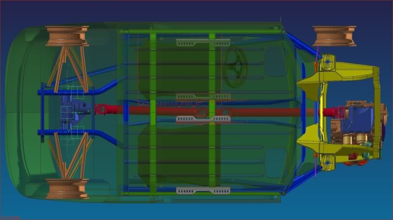
Going on the current accepted best practice of using the longest wishbones possible, and using some first guesses of KPI and camber etc for the rear end, I ended up with a first scheme as shown. Before its possible to tie this down properly I need to model in the front suspesion so I can determine roll moment distribution etc... Can't do one end inpendently of the other as thats not how they work! Its now also time to get some brake calipers into the machine and think about rear wheel bearing setup to allow an upright to be designed. This is going to be what determines my outer wishbone pivot positions, and therefore in turn my inner ones - so its important to move the rear of the car along.

Anyways - enough waffle - here's a couple more images:
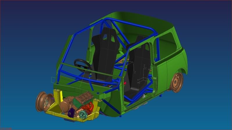
Nakid
Posted Image


There are members missing from the back of the rollcage that run up to the main hoop - before anyone mentions it. I've been moving the pick ups about so much at the back I just deleted them for now.
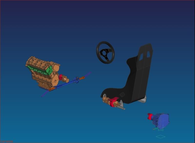
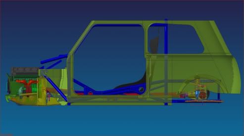
Clothed
Posted Image

Posted Image

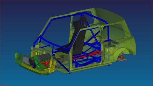
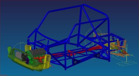
As part of the work on the front end I've started to detail the front of the rollcage more. You can see this in the fact that there are a couple of members floating in space! As a concession to manufacturing ease I have changed the way the front subframe pick ups are triangulated a little, but not got round to moving those errant tubes just yet.....!
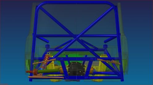
Rear End layout...
Posted Image

Edited by SukiDawg, 20 June 2009 - 05:06 PM.


#30 daveeeeee

daveeeeee

    Super Mini Mad

  • Members
  • PipPipPipPipPipPip
  • 684 posts

Posted 24 June 2009 - 09:55 AM

awesome.


0 user(s) are reading this topic

0 members, 0 guests, 0 anonymous users