Jump to content


Photo

Little Less Conversation A Little More........


  • Please log in to reply
246 replies to this topic

#46 SukiDawg

SukiDawg

    Speeding Along Now

  • Members
  • PipPipPipPipPip
  • 304 posts

Posted 23 September 2009 - 02:27 PM

Hi,

I'll do everything myself, but do have a lot of knowledge from my profession so in that respect I am lucky.

All of the CAD data here is my own work, modelled from a clean sheet. 3D scanning technology does exist, but you would be looking at in excess of 5k or more to scan a full shell. If you have your engine, and you have your shell, then the only way to get things how you want them is to crack on and get stuck in - in my opinion. Buy yourself a small surface table and a height gauge from ebay, plus an engineer's protractor, calipers, rule, etc and you can measure all of the major engine castings to a sufficient level of detail for an engine installation. The shell I did in a similar way but with a tape measure and a sketchpad.

Hope this helps....

Edited by SukiDawg, 23 September 2009 - 02:28 PM.


#47 Sean12

Sean12

    Mini Mad

  • Noobies
  • PipPipPipPip
  • 124 posts

Posted 23 September 2009 - 08:58 PM

cool cool, cheers for the reply sukidawg, i will crack on and see how it goes ! does anyone know of anyone on the forum that used a honda fireblade before ?

cant wait to watch this progress sukidawg, lookin awsome !

#48 custodia

custodia

    Speeding Along Now

  • TMF+ Member
  • PipPipPipPipPip
  • 330 posts

Posted 24 September 2009 - 10:01 AM

Lovely project you have there. I did a CAD mini for a uni project but it is nowhere as detailed as yours. Keep up the good work.

#49 cptkirk

cptkirk

    Camshaft & Stage Two Head

  • Members
  • PipPipPipPipPipPipPipPip
  • 1,799 posts
  • Location: West Sussex
  • Local Club: B.M.C. + Chiminiclub

Posted 24 September 2009 - 03:25 PM

The model looks really good. It is inspiring me to make something of my own, pure racer though. As above - Keep up the good work......

#50 SukiDawg

SukiDawg

    Speeding Along Now

  • Members
  • PipPipPipPipPip
  • 304 posts

Posted 06 October 2009 - 12:22 AM

Been spending a fair amount of time on this again this week. Not a great deal to post up though, because I have been continuing to attempt an understanding - even a slight appreciation would do - for suspension geometry and the ins and outs of the unequal double wishbone arrangement (I am a real hit at partys recently....)


I am making some headway... I have a spreadsheet now that gives me the actual camber and track with changes to wheel bump and rebound, and also vehicle roll. This is with the vehicle rolling about its static roll centre so not 100%, i.e. the calculation does not take into account the roll centre moving as the vehicle rolls. I have also only done this for the rear at the moment. The results seem to tie in with the trends described in some of the text books I've picked up on suspension, and also I have checked the spreadsheet against the CAD geometry and it all ties up... All in all its been a right head bender but I am quite happy with the result.

A few of the many charts I am now generating! The first hurdle is to be able to generate them - now the hard bit of interpreting them into something useful!

Posted Image

Columns are different geometries.

The top row shows the achieved camber angle on the vertical axis and the wheel vertical position on the horizontal (if that makes sense). The different lines are the camber characteristic at different roll angles.

The lower row shows the change in the rear track (I am working with a figure of 1300mm rear track at the moment) with suspension movement (horizontal axis) and vehicle roll (different plots on the same axis).


As for the CAD, well it looks kind of like this at the moment while I shag about with the suspension... Need to know where those pivots go :thumbsup:

You might notice the rear suspension geometry has changed a lot...

Posted Image

#51 The_R1_Kid

The_R1_Kid

    Learner Driver

  • Noobies
  • PipPip
  • 11 posts
  • Location: Oregon, USA

Posted 09 October 2009 - 12:02 AM

I just mouse wheel clicked your cad picture to try and spin it... I use solidworks way too much.

nice work

#52 SukiDawg

SukiDawg

    Speeding Along Now

  • Members
  • PipPipPipPipPip
  • 304 posts

Posted 18 October 2009 - 12:09 PM

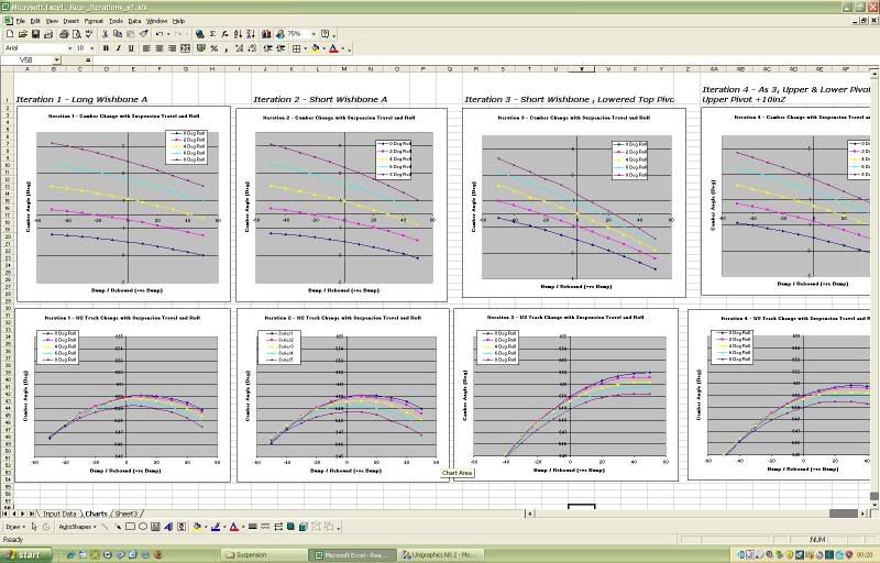
Well, not much to show for the progress this week other than a few more graphs and lots more thought.

Its been kind of mentioned in another thread that its best to "get out in the garge and do it! instead of doing loads of bla bla!", and I don't know if that was actually directed at me or not, but either way man didn't walk on the moon without some prior preperation, engineering thought and planning so I'll carry on as I am and try to make the best design possible before cutting metal. Others can attempt to imitate Z cars or whatever (this forum abounds with people trying to copy them), but to do something original I don't believe the first steps should involve the angle grinder. Also - if you are going to invest several thousand pounds of your own money into producing a vehicle, I'd rather stretch my brain before my biceps. I am a professional automotive engineer too, so its not my culture to not think about things first.

Anyway, there rests the case for the defence!

It was supposed to be a field trip today. I have a friend who gets involved in the garage work (or has on previous projects) and we had planned to go to the Donington Motor Museum yesterday to have a look at suspension construction etc on all of the old F1 cars etc that are there (Some photos from the web). These days the techniques used to make uprights / wishbones etc are far beyond the capabilities of a home engineer - but back in the 60's and 70's they were mostly fabricated steel so it would be a useful trip I think. Unfortunately, Matt (my assistant) has been taken with some bug that's going round so its been postponed until next week.

Instead of going to Donington, I decided to clear out my spare room and loft. A long overdue exercise. It proved to be a good thing, because I came across some notes from University I thought were long lost. Amongst them these:

Posted Image

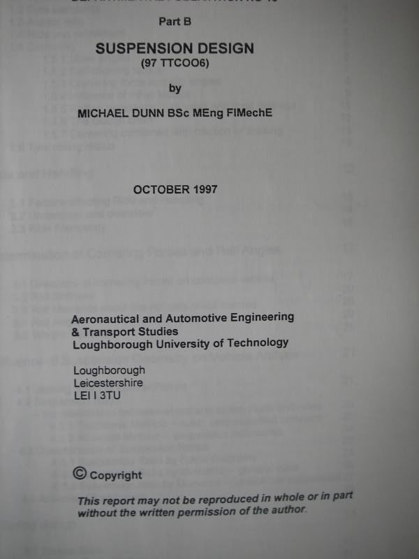
Which should really help, as there are some worked examples with actual numbers for roll etc in them. Mike Dunn (the lecturer) was chief engineer for Ford on the Sierra project, so he should talk some sense.

#53 minidream94

minidream94

    One Carb Or Two?

  • Members
  • PipPipPipPipPipPipPip
  • 1,233 posts

Posted 18 October 2009 - 02:49 PM

Sukidawg, this is looking fantastic mate it is all looking brill, i have also subscribed.

i have just returned to Uni and i have been planning to do a BEC mini for a while now myself and tie it into my dissertation. I have luckily been able to aquire a free mini shell an a free honda fireblade engine (1998). i have yet been able to decide whether to make it FWD or RWD, i just cant make up my mind. i would love to do it RWD but i just cant ignore the fact that it is goin to cost more, but how much more ??? does anyone have any experience at this ? oh i must add i wont be buyin a kit such as zcars or promotive i will have to make it all myself. sorry got carried away there, what i started the reply to say was, the CAD work looks fantastic, i also do CAD as a job to an plan to begin a model soon, did you model the engine your self or download it from somewhere ? been tryin to find a scale model of a honda fireblade engine but cant find one anywhere ! have you heard about these 3d scanners ? was thinkin of poss trying to get this done on the shell of my mini to get a 3d model of the shell to begin the design, i also wanted to ask about the turbo plans as have been think about this myself. have you done much research on it yet an if so have you found many companys that turbo bike engines or were you planning on doing all the work youself ?

all the work you have done so far mate looks fantastic, cant wait to watch it progress, good work with the sand blasting to, looks awsome !!!


You could check these out http://www.bigccracing.com/

#54 cptkirk

cptkirk

    Camshaft & Stage Two Head

  • Members
  • PipPipPipPipPipPipPipPip
  • 1,799 posts
  • Location: West Sussex
  • Local Club: B.M.C. + Chiminiclub

Posted 20 October 2009 - 03:28 PM

Dave

Incase you missed my post on the zcars technical forum I stumbled across this site the other day:

DP Cars

There are links to iges files of hayabusa and R1 engines + other bits at the bottom of the page, also its worth going to the build pages as this guy is trying to make a chain driven, 4 wheel drive, hayabusa powered bespoke racer, some interesting design work going on, not sure I agree with it all but ideas spawn other ideas. Its the kind of layout I was thinking about for my next one, with the engine sitting at the side of the driver.

#55 The_R1_Kid

The_R1_Kid

    Learner Driver

  • Noobies
  • PipPip
  • 11 posts
  • Location: Oregon, USA

Posted 21 October 2009 - 01:30 AM

Dave

Incase you missed my post on the zcars technical forum I stumbled across this site the other day:

DP Cars

There are links to iges files of hayabusa and R1 engines + other bits at the bottom of the page, also its worth going to the build pages as this guy is trying to make a chain driven, 4 wheel drive, hayabusa powered bespoke racer, some interesting design work going on, not sure I agree with it all but ideas spawn other ideas. Its the kind of layout I was thinking about for my next one, with the engine sitting at the side of the driver.


Hi. Just wanted to say the AWD chain drive concept works very well. It is very efficient packaging wise and drivetrain loss wise. The power never has to turn 90 degrees through a ring and pinion. like it does in a conventional AWD layout.
The only idea that didn't work very well in the prototype is the inboard brake that brakes through the diff. If you try to trail brake into a corner the diff will lock up and spin you, or at least get very unstable.

#56 SukiDawg

SukiDawg

    Speeding Along Now

  • Members
  • PipPipPipPipPip
  • 304 posts

Posted 21 October 2009 - 04:17 PM

Hey,

Well that certainly is a very interesting link! What a project that is - and what a budget!!!!! I guess we all wish we had the resources to pursue our ambitions to that extent. Putting that to one side though, the project itself is extremely interesting even if I agree with the Captain, I am not sure I would have approached it in the same way. Everyone goes about things in different ways though, and the chap's engineering pedigree is not in doubt.

I have a very very good friend who is based in Portland (Bristish ex-pat) and involved in the engineering scene there - so I asked if he knows the guy....


Also some very good links to other builders... the Kimini for instance (link to follow when I'm back home)....

#57 SukiDawg

SukiDawg

    Speeding Along Now

  • Members
  • PipPipPipPipPip
  • 304 posts

Posted 24 October 2009 - 09:40 PM

The Kimini.....

I don't know if that project has been on here before, and its perhaps a little overengineered in places (stainless steel floor!!), but defintely worth a read for interest...

Edited by SukiDawg, 24 October 2009 - 09:40 PM.


#58 cptkirk

cptkirk

    Camshaft & Stage Two Head

  • Members
  • PipPipPipPipPipPipPipPip
  • 1,799 posts
  • Location: West Sussex
  • Local Club: B.M.C. + Chiminiclub

Posted 26 October 2009 - 08:06 AM

The guys name is Kurt, he is on some of the american forums for the Honda K20 engine. Fair play to the guy for building the car, but even bigger pat on the back for writing a book on it. I will get a copy in my library in the future.

His latest project looks interesting too, the Midlana, very Caterham'esque but mid engined and designed from scratch.

I have bought my next shell now and hope to start the design work in the new year with a view to starting to build by the end of next year, Busa powered, L/H drive with the engine to the right of the driver, for sprint and hillclimb. Really looking forward to getting my hands dirty on this one.

Enough of hogging your build diary, keep up the good work Dawwwwwg.

(Rockingham is 50/50 at the mo, will keep you posted)

#59 SukiDawg

SukiDawg

    Speeding Along Now

  • Members
  • PipPipPipPipPip
  • 304 posts

Posted 10 November 2009 - 12:59 PM

Hi,

Well I thought as nothing has been added to this for a while I ought to say something about whats been happening at this end.

The answer is a hell of a lot of reading and learning. Not much designing.

As I have read more into the subject of suspension engineering and its effect on the dynamic handling of the vehicle, the importance of roll centre axis location in relation to the mass centroid axis of the car has come out as being really really important. I've always known that there was no point in designing the rear suspension in isolation from the rear - and now I can put some reasoned description to why this is! Static roll centre axis is also not the whole picture, as the roll centres move with suspension bump/rebound travel and vehicle roll and what has come out from reading around the subject is that we want these roll centres at front and rear to move more or less in the same way as the vehicle corners.

What does that mean - well it means that I really have to get my spreadsheet of component weights and locations better sorted than it currently is - and this is taking time to develop. In many ways, I have been learning more about what I don't know than what i do - hence what appears to be a freeze is actually a catch up!

So - we're still moving forward with the project, just not with anything I can really post up pictures to show right now.

So keep following guys, your comments are encouraging - and when the time comes to show something I will...


Cheers,

Dave.

#60 340i

340i

    Learner Driver

  • Noobies
  • PipPip
  • 13 posts
  • Local Club: no

Posted 07 January 2010 - 06:37 AM

just found this project and holy sh$% i like your work! who cares if you haven't got sunk into the fabrication, because when you do its gonna be a hundred times easier with all the work you've done on cad. im really glad you changed the rear suspension design, as i seen it on the previous page and wondered what you were up to with the top arms angled like that you'd be losing camber under bump. you're probably well ontop of this now, but are you also considering the camber change under acceleration (as well as the mentioned roll, etc)? the reason i say, is that if it were me i'd be aiming for next to no camber gain under bump, so that when you launch it the tyre keeps full contact (and grip) with the road. at the end of the day, you're never going to be able to design the 'perfect' suspension geometry till you actually drive the thing, so just make sure that as many of the points are adjustable as possible.
keep up the good work, i cant wait to see how this progresses.


0 user(s) are reading this topic

0 members, 0 guests, 0 anonymous users