Jump to content


Photo
- - - - -

Electrifying Trogdor


  • Please log in to reply
92 replies to this topic

#16 Anchoright

Anchoright

    Mini Mad

  • Noobies
  • PipPipPipPip
  • 127 posts
  • Location: Los Angeles

Posted 29 August 2016 - 02:27 PM

Some friends took me to the Petersen Auto Museum in LA last Friday. They had a ton of cars there including this one:

Attached File  image.jpeg   40.69K   15 downloads

Looks like an old car, right? Yeah it is. But check out the plaque!

Attached File  image.jpeg   48.87K   24 downloads

It's an EV from 1915! Sure, ok, it goes 20 mph but all the cars went 20 mph back then. It has an 80 MILE range!!!! Eighty miles on a single charge, electric vehicle, made in 1915!

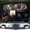
So electric vehicles can't be that complicated. And they are not. Here's a simple diagram I drew on my iPad to show the different parts involved. It is quite simple:

Attached File  image.jpeg   56.94K   35 downloads

Try drawing something like this for a regular engine. It would involve air, electricity and gas, and how you need to perfect those substances and combine them to get the pistons to turn. It would be far more complicated.

Let me go through this quickly for you.

Outlet - that's your wall electric outlet.

Charging thing - there's many different kinds. Basically what converts the power from your wall to the power you need to plug into your car. If you go to a charging station, that's what it is, or you can buy little ones for home. I got a neat one that can plug into 110V or 240V, and is small enough for me to throw in the trunk so I always have it with me and will never be stranded. Check it out: http://www.evwest.co...products_id=298

Plug - where you plug into the car. Your fuel cap equivalent.

Battery charger - something like a laptop charger but bigger. It takes the electricity and pumps it into the batteries. There are many different kinds. The guys at EV West told me the best one for my Tesla batteries, and since I wanted a faster charging time they recommended that I get two. The second one is on a switch. This way if I pull up to an outlet that might have a small fuse I only use one charger, or if I'm at a well fused outlet I can use both chargers and charge in half the time.

Battery - The electricity goes from the charger to the batteries, and there your electric fuel is stored. The batteries need to be wired in such a way to come to a total of (roughly) 110V for the electric motor that I used. There are other motors that need a different battery configuration, like 48V or 300something V....

Contactor Box - a fancy name for a plastic box that keeps the relays dry. If they got wet there would be problems. It has two glorified relay switches in there, one for the DC to DC converter, one for the Controller. It also has a shunt in there to give a gauge the correct battery capacity reading, and another thing to tell the chargers when to stop charging because the batteries are full.

DC to DC Converter - this is basically the equivalent of the alternator. It charges your regular Mini battery so that the lights and the horn and the wipers work.

Controller - this guy does the magic. So a battery is DC current. The motor is an AC motor, using AC electricity. The controller takes the DC current from the battery and chops it up to make AC current. If you want to drive slow it chops up the current slowly. If you want to drive fast it chops it up faster.
It can be programmed to do all sorts of cool stuff. Like when you're stopped at a traffic light the car can "crawl" like an automatic, or not, it also regenerates electricity with braking or while coasting, you can determine how much or how little power you want, all sorts of stuff.
The controller gets pretty hot. So it needs to sit on a heat sink. The guys at EV West designed a cooling plate that connects to the type of cooling system that you would install in a water cooled computer, and it keeps the controller cool.

Motor - pretty straight forward AC, three phase electric motor, used for pumps or other stuff. There are many different kinds. There are also DC motors that would use a different configuration. AC motors are better, but there's a whole science behind the reasoning. I just went with the motor that EV West told me would be best for my car.

Plate - reading other people's EV stories usually entails a whole section on the plate. Essentially, how do you plug the electric motor to the rest of the drive train. For me it was super easy, because I had already done the Suzuki G-10 conversion - which of course also included the subframe. And a company in Canada makes a plate to connect directly to the Suzuki G-10 transmission. It was simply plug-and-play. (Or at least I thought!)

The rest of the car is the same. It's best to keep the manual transmission on the car, because an automatic transmission sucks up too much effort from the engine and it's all wasted.
There's two schools of thought as to whether to use a clutch or not. The concept is that since the electric motor is not spinning when you are stopped, you can change gears freely. While in theory it is not necessary to disengage an engine that is not spinning, in practice it doesn't quiet work so well. When it comes down to it, if you want a performance car that works well, use the clutch.
In the end the car drives differently than a manual even though you have a clutch pedal and a stick shift, but I'll go into that more later on. It's actually a more "natural" way to drive than the conventional manual car. It's also quite easy for someone who has no idea what a stick shift is, to drive the car as if it were an automatic (and just ignore the third pedal).

#17 Anchoright

Anchoright

    Mini Mad

  • Noobies
  • PipPipPipPip
  • 127 posts
  • Location: Los Angeles

Posted 29 August 2016 - 02:37 PM

speaking of carbon you should have a look at http://www.carbonweezel.co.uk/


Wow, nice stuff!

#18 Anchoright

Anchoright

    Mini Mad

  • Noobies
  • PipPipPipPip
  • 127 posts
  • Location: Los Angeles

Posted 30 August 2016 - 03:27 PM

Shopping time!

Bitcoin went up to $600. I cashed out 18 BTC and drove on down to EV West to pick up everything I needed.
Going there is like visiting Santa's North Pole workshops - there's always super cool stuff going on!

Attached File  image.jpeg   41.81K   10 downloads Attached File  image.jpeg   67.7K   11 downloads Attached File  image.jpeg   37.86K   10 downloads

They had my stuff ready for me when I got there, and they walked me through each thing, what it was, how to connect it, I came with a list of questions and they answered every one.

Attached File  image.jpeg   56.26K   6 downloads Attached File  image.jpeg   53.27K   9 downloads

On the way down there I took the gizzards from Trogdor to their final resting place, and also picked up a refurbished Suzuki manual transmission.

Attached File  image.jpeg   40.15K   12 downloads Attached File  image.jpeg   74.65K   13 downloads

Now one of the crucial parts of the install is the little coupling that goes on the shaft of the electric motor and bolts to the flywheel and clutch. These motors last forever. And the coupling is a tight fit that needs to be heated up to go on, and once on it will never come off. If you get it wrong, the motor is as good as trash. I didn't want to deal with that risk myself so I asked John from EV West if he could do it. He was more than happy to! So they put on that coupling and also the connecting plate, so I could just plug it into the clutch and transmission.

Attached File  image.jpeg   39.48K   26 downloads

They would have mounted the clutch and joined it to the transmission for me, but whoever I ordered the new clutch from sent me the wrong one. And also the wrong flywheel. So we couldn't put it all together until I got the right parts, which I did on the way home, just stopping into Pep Boys. Later I found out that the reason why the clutch and fly wheel were wrong was because I had ordered performance parts and the company that makes the performance clutch didn't have it for the G-10. They were for another Suzuki engine.

So I got the parts, and hey, let's get this all together before the sun goes down!

Attached File  image.jpeg   50.89K   12 downloads coupling and the connector plate on the motor
Attached File  image.jpeg   55.69K   9 downloads next goes on the fly wheel
Attached File  image.jpeg   75.64K   7 downloads with a little locktite action on the bolts so they don't come off
Attached File  image.jpeg   50.39K   6 downloads lining up the clutch
Attached File  image.jpeg   55.2K   7 downloads and on she goes
Attached File  image.jpeg   45K   5 downloads don't forget the clutch bearing
(which I didn't grease so the grease wouldn't splatter over the clutch)
Attached File  image.jpeg   51.82K   7 downloads on goes the transmission
Attached File  image.jpeg   55.5K   38 downloads and the day is done.


That was a happy day!

Edited by Anchoright, 30 August 2016 - 03:32 PM.


#19 Anchoright

Anchoright

    Mini Mad

  • Noobies
  • PipPipPipPip
  • 127 posts
  • Location: Los Angeles

Posted 31 August 2016 - 01:19 PM

The next chapter in this story is the same as any other motor conversion story. But that's what makes it interesting!

How do you make it fit in the tiny Mini?

Well with all my studies and preparation, this was supposed to be the easy part. I could have gone with any other transmission that could probably handle the 150hp far better than the Suzuki, but I went with the Suzuki because I wouldn't need to change my subframe and I wouldn't need to change my axles. I could use the subframe and the axles from the last conversion I did, which was to fit the Suzuki G-10 engine.

Yeah. That didn't happen. The motor was about 2" too long. It needed to be scooched over. Which brought back nightmares of the failure that I had last time with measuring the axles and how the axle fell off while going around a corner!

I didn't take good pictures of it, sorry, but I simply got a thick piece of steel and drilled holes to move it all over. Tacky and unprofessional, but I wasn't too happy that everything needed to move!

The Suzuki engine was held in by three locations - driver's side front and back, and passenger side on the front. And that held the motor fine. I figured that I could use the same mounting locations, so for the driver's side, which is where the end of the electric motor sat, I took a long piece of steel, bolted it to the end of the motor, and bent it to meet the mounting points on the subframe. The passenger side was mounted to the transmission, so nothing changed except being moved over a couple inches. I used all new mounts, since I figured it's a good time to change them.

With my one day off every blue moon, this mounting complication took over a month to deal with, I had to give back the engine hoist to the rental company, so my motor sat like this for a very long time!

Attached File  image.jpeg   50.67K   49 downloads

(Sorry I dropped the ball with taking more pics!)

#20 Anchoright

Anchoright

    Mini Mad

  • Noobies
  • PipPipPipPip
  • 127 posts
  • Location: Los Angeles

Posted 31 August 2016 - 01:38 PM

The motor and transmission now in, where do I put everything else? I wanted to put as much as possible into the engine bay to counterbalance the weight of the batteries in the rear.

EV West designed a plate that screws onto the end of the motor, so that the controller can sit on top of the motor. It's designed to work perfectly with a VW, but it didn't quite fit for me. So I hacked off the end and then used angle steel to brace it to a bolt on the transmission plate.

Attached File  image.jpeg   44.83K   25 downloads

Next I welded a bracket to hold the battery chargers over the transmission. Again, I dropped the ball taking pictures but at least I have this pick of half of the bracket!

Attached File  image.jpeg   45.68K   25 downloads

On went the battery chargers:

Attached File  image.jpeg   63.47K   38 downloads Attached File  image.jpeg   71.4K   21 downloads Attached File  image.jpeg   62.92K   20 downloads

#21 micraminiman

micraminiman

    Mini Mad

  • Members
  • PipPipPipPip
  • 151 posts
  • Location: Scottish Highlands

Posted 01 September 2016 - 08:17 AM

This is really cool. My dream is a powerful electric motor in my Mini.

Im an Engineer in a factory that makes specialist Lithium Battery Packs for all types of applications, including EV and Military.


Keep up the good work, and best of luck with it all.


#22 keegan

keegan

    Just On Tickover

  • Noobies
  • Pip
  • 8 posts
  • Location: Reading

Posted 01 September 2016 - 09:07 AM

Ditto, following this with interest!  


#23 Anchoright

Anchoright

    Mini Mad

  • Noobies
  • PipPipPipPip
  • 127 posts
  • Location: Los Angeles

Posted 01 September 2016 - 02:17 PM

This is really cool. My dream is a powerful electric motor in my Mini.
Im an Engineer in a factory that makes specialist Lithium Battery Packs for all types of applications, including EV and Military.
 
Keep up the good work, and best of luck with it all.


You should! Half the battle is won if you have that sort of connection with batteries!
Do you know anything about the Lithium Titanate batteries? They will be a game changer I think.

#24 Anchoright

Anchoright

    Mini Mad

  • Noobies
  • PipPipPipPip
  • 127 posts
  • Location: Los Angeles

Posted 01 September 2016 - 02:19 PM

I forgot to take pics of the next step, I thought I did but I can't find them. So I'll add a link to the YouTube video from EV West that I followed to do it. It took about 20 min and I did it on the dining room table.

Basically it's gluing the chill plate to the base of the controller. The controller heats up because it needs to regulate the electricity going through it, converting it to AC for the motor. Some EV conversions just grab a GIANT hunk of aluminum to mount the thing to, but EV West made this chill plate so you plug in a CPU radiator (like this one so you know what I'm talking about).

Pretty simple job, except there's one thing the video doesn't say. You need to watch the finish of the top side of the controller while you're spraying the cleaner all over the base. I got permanent drip marks on mine because I wasn't careful.

How to install the chill plate

Edited by Anchoright, 01 September 2016 - 02:27 PM.


#25 Anchoright

Anchoright

    Mini Mad

  • Noobies
  • PipPipPipPip
  • 127 posts
  • Location: Los Angeles

Posted 02 September 2016 - 02:24 PM

Next the controller mounts to the mounting plate. That was super fast too.

Attached File  image.jpeg   67.19K   24 downloads

You can see those nasty drip marks from the carb cleaner I used to get the sanding dust off the base. I'm hoping one day to somehow polish them off or ignore them!

So this is what we've got so far! Bottom left is the electric AC50 motor, bottom right is the transmission from the Geo Metro (Suzuki) G-10.
Top left is the Curtis Controller and top right are two battery chargers.

Attached File  image.jpeg   88.03K   21 downloads

#26 Anchoright

Anchoright

    Mini Mad

  • Noobies
  • PipPipPipPip
  • 127 posts
  • Location: Los Angeles

Posted 02 September 2016 - 02:37 PM

Next up is the radiator and pump. I had gotten it from EV West as part of my shopping spree when they gave me everything I needed. (I put two and two together later that it was a computer radiator and pump.)
The challenge was where to put it!

Somehow by an insane fluke, the radiator fits perfectly underneath the battery chargers.

Attached File  image.jpeg   59.34K   10 downloads

For the pump/reservoir I took a page out of the Geo Metro conversion that I did, and utilized the secret space in the wheel well. I put my charcoal box up there with the Geo conversion. Tons of real estate up there!

I had cut a hole into the wheel well to fit the Geo motor, and that hole now looked ghastly. So I covered it up with an aluminum sheet and pop riveted it on, putting the pump/reservoir behind it, sticking out far enough to expose the fill cap. Then I drilled a couple holes with a dremel for the hoses to go through, trying to make it look professional!

Attached File  image.jpeg   66.9K   23 downloads

.

#27 Anchoright

Anchoright

    Mini Mad

  • Noobies
  • PipPipPipPip
  • 127 posts
  • Location: Los Angeles

Posted 02 September 2016 - 02:41 PM

The DC to DC Converter fits perfectly in the space inside the dashboard on the passenger side. So I stuck it there and drilled it in. Quick job and I didn't think to take pictures, sorry!

#28 Anchoright

Anchoright

    Mini Mad

  • Noobies
  • PipPipPipPip
  • 127 posts
  • Location: Los Angeles

Posted 02 September 2016 - 02:49 PM

And for fun I decided to get some "blood" to fill the cooling system with!

XSPC ECX Ultra Concentrate Coolant, Blood Red

.

Edited by Anchoright, 02 September 2016 - 02:51 PM.


#29 Anchoright

Anchoright

    Mini Mad

  • Noobies
  • PipPipPipPip
  • 127 posts
  • Location: Los Angeles

Posted 03 September 2016 - 02:43 PM

Almost finished installing all the hardware. Two things left to go, the charging port, and the accelerator.

I didn't want to have to run a wire from the back of the car to the front for the chargers. I figured it would be better to have the charging port up front with everything else. So I drilled a hole in the front fender. I used a gas door from a jeep. I think it turned out a little big, but oh well, damage is done!

Attached File  image.jpeg   44.66K   14 downloads
Attached File  image.jpeg   42.4K   5 downloads
Attached File  image.jpeg   36.35K   6 downloads
Attached File  image.jpeg   41.16K   17 downloads
Attached File  image.jpeg   45.99K   14 downloads

A special gas pedal is needed to send the correct electric signal to the controller. The cheapest way to go is actually a used pedal from a Toyota Prius.
It didn't quite fit as is, so I had to weld up a little base to hold it at the right angle.

Attached File  image.jpeg   95.22K   12 downloads
Attached File  image.jpeg   42.08K   5 downloads
Attached File  image.jpeg   78.15K   3 downloads
Attached File  image.jpeg   44.94K   12 downloads

.

#30 Anchoright

Anchoright

    Mini Mad

  • Noobies
  • PipPipPipPip
  • 127 posts
  • Location: Los Angeles

Posted 04 September 2016 - 12:53 PM

So at this stage everything was in place. Next is the wiring, joining everything together!
I spent a very long time just memorizing and getting familiar with this:

Attached File  image.jpeg   107.14K   33 downloads


0 user(s) are reading this topic

0 members, 0 guests, 0 anonymous users