Jump to content


Photo

Supercharger Inlet Manifold!


  • Please log in to reply
27 replies to this topic

#16 1987_ParkLane

1987_ParkLane

    Up Into Fourth

  • Members
  • PipPipPipPipPipPipPipPipPip
  • 2,671 posts
  • Location: N/A
  • Local Club: The Mini Forum

Posted 28 October 2008 - 10:07 PM

So Tom got in contact with me asking if I could kindly measure mine, and finding it would help a lot of people, here we go:

Posted Image

Posted Image

Hope they help.

Cheers

#17 Surfbluegarage

Surfbluegarage

    AKA mini_mad_daps

  • Traders
  • PipPipPipPipPipPipPipPip
  • 1,547 posts
  • Location: nottingham
  • Local Club: Notts About Minis

Posted 29 October 2008 - 07:18 PM

just another few things... A. does anyone know how thick the plate is that bolts to the head? im guessin at 6-8mm and B. how far down does the base plate that the charger sits on sit below the top of the head. i.e level with where the rocker gasket sits on.

#18 minibazzer

minibazzer

    Stage One Kit Fitted

  • Noobies
  • PipPipPip
  • 87 posts
  • Local Club: None

Posted 30 October 2008 - 10:30 AM

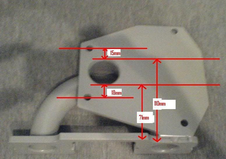
You dont have to cut off those lugs to clear the manifold, if your making the kit, you might as well just run a single belt that does alternator, water aswell rather than use a V belt. It means you can get the charger further to the left and make everything so much easier. If you go for the Jonspeed/Vmaxx set up you will need to machine into the charger, if you use one drivebelt, you wont need to.

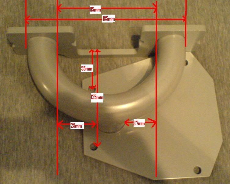
On mine, I've machined away all of the area in red;

Posted ImagePosted Image


just out of interest, what was your thought behind machining away the area you marked? I have purchased the Vmax Scart kit and there has been no machining done to any part of the charger that attaches to the inlet manifold. I would be very keen to understand the benefits of doing this and/or the implications of not doing it. Also, I presume that I would need to remove the blades before doing any form of machining in this area?

Cheers, Si

#19 Surfbluegarage

Surfbluegarage

    AKA mini_mad_daps

  • Traders
  • PipPipPipPipPipPipPipPip
  • 1,547 posts
  • Location: nottingham
  • Local Club: Notts About Minis

Posted 30 October 2008 - 07:31 PM

hmmmm very good point... but i was told never to remove the blades as the way they went in is the way they have to stay and to remove them you could possibally misalign them and with thou between them.... could be bad..lol but saying that ive also bin told to grind away an area in the thick spot of the charger on the bottom where my pen is as to allow flow. As the hole in the manifold sits underneath that slab of metal

#20 Sammy D

Sammy D

    One Carb Or Two?

  • Members
  • PipPipPipPipPipPipPip
  • 977 posts

Posted 31 October 2008 - 11:33 AM

You could do it with the blades still in there but it's a bit hektic. Just take the charger apart, it comes apart pretty easy.

Like zis;

Posted Image

Posted Image

Much better flowing than the Vmax/Jonspeed design.

Some food for thought.

#21 Tomf

Tomf

    Baby Tom

  • Traders
  • PipPipPipPipPipPipPipPipPipPip
  • 6,440 posts

Posted 31 October 2008 - 12:03 PM

Looks like a much better design that the kits on the market, i think iv decided on a different way of amking my inlet, im just waiting on parts to come through the post then ill start on making it, it should offer alot better flow than the kits on the market offer and should be alot cheaper to make...

Where did you get your kit from sam? as i remember reading that your brought it as a full kit in the end...

#22 1275midget

1275midget

    Stage One Kit Fitted

  • Noobies
  • PipPipPip
  • 73 posts

Posted 31 October 2008 - 07:07 PM

what's the thinking on whether the inlet manifold is balanced for each port?

I know its important for a non-forced induction setup, and I'd noticed that the images here, one is centralised on the manifold (same distance for the air to go) and the other appears not to be...

my plan was to adapt a standard mini single carb manifold with a sort of s-bendy thing to put the hole in the centre of the charger outlet - as it's in a midget I have a lot more space "behind" the engine to play with..

Rob

#23 1275midget

1275midget

    Stage One Kit Fitted

  • Noobies
  • PipPipPip
  • 73 posts

Posted 20 November 2008 - 10:26 AM

bump >_<

#24 Surfbluegarage

Surfbluegarage

    AKA mini_mad_daps

  • Traders
  • PipPipPipPipPipPipPipPip
  • 1,547 posts
  • Location: nottingham
  • Local Club: Notts About Minis

Posted 18 December 2008 - 09:46 PM

i thought with forced induction it didnt matter to much if it was balanced from the off as the back pressure when valaves are closed equals out in all chambers?
spose there no stopping you mounting it this way... i thought about that but went with an all steel one rather than mixin cast with non cast as to be able to wled to and adapt more.
my mates using a mini manifold.. guess which one?lol

#25 ferrox_666

ferrox_666

    Mini Mad

  • Noobies
  • PipPipPipPip
  • 126 posts
  • Local Club: you tell me !

Posted 20 December 2008 - 05:57 PM

'Ideally' one would want both ports to be equal distances but this world is far from perfect..
If its in a Midget i think fabricating a plenum under the charger feeding both ports would make best use of the space available, ..or a f*&k off turbo lol

#26 nobbycameron

nobbycameron

    Mini Mad

  • Noobies
  • PipPipPipPip
  • 130 posts
  • Local Club: .

Posted 16 June 2009 - 09:54 PM

hello, im doing the same as you, making the kit from scratch.
local car dismantler and they have a
the manifold seems fairly straight forward, just a bit of time with the welder.

My idea at the moment with regard to the pulley is to try and find one off the shelf and get a longer crank bolt made, i think this will be cheaper than getting a whole pulley made, the belt is a standard 6PK whick is widely used in cars for alternators etc. I went to my local car dismantler and they have a massive rack full of pulleys, all i need to do is calculate the size i need for a 1275 running 10psi then i sure there will be a way of attaching it to the mini pulley. Also no need to machine a keyway would save a lot of hassle,

my question is to you is how do you calculate the required pulley size ofr 10psi, my calculations keep showing up with a pulley ratio od 1:1 which is way too slow... any suggestions...

#27 Rosslin Racing

Rosslin Racing

    Up Into Fourth

  • Traders
  • PipPipPipPipPipPipPipPipPip
  • 2,408 posts
  • Location: Burgdorf.
  • Local Club: SMP beo BMC swiss

Posted 19 June 2009 - 01:50 PM

You could do it with the blades still in there but it's a bit hektic. Just take the charger apart, it comes apart pretty easy.

Like zis;

Posted Image

Posted Image

Much better flowing than the Vmax/Jonspeed design.

Some food for thought.


That manifold looks tonnes better. The one I have is a plate with a hole in it.!

#28 smj

smj

    Mini Mad

  • Members
  • PipPipPipPip
  • 246 posts

Posted 19 June 2009 - 07:11 PM

If anyone is stuck making the sheet metal work for their inlet manifold, or any of the flat stuff for their charger project, give me a dimensioned sketch(scanned drawing, photo, paint file whatever) and i can draw it in autocad and get it laser cut and posted to you very very reasonably priced, you can find us at www.lasermaster.co.uk, or ebay search for profilemen. I am starting my own supercharger project at the moment but am just now building a low compression engine up before i get stuck into the fitting up stage etc etc


1 user(s) are reading this topic

0 members, 1 guests, 0 anonymous users