OK if any of you remember the story so far, when I turn on ign. the fuel gauge goes straight to max. Its the early mk1 type without the voltage stabiliser. As I broke the old one investigating this I have now bought another old speedo etc with the same type of gauge and fitted that. The gauge is def. earthing ok - I ran an extra earth wire from the mounting screw to be sure and have tested it. I have also disconnected the green /black wire from sender and taken a new one direct from the sender to the gauge. Now when I switch on - nothing! Unless temporarily I bridge the connections on the sender and it goes straight to max again and stays there until I turn ign. off and on again and it then shows empty. There is approx 7.5 volts showing across the sender terminals and same from terminal on gauge - I believe this should be 10?. Other terminal on gauge shows 12volts as I presume it should.
Where do I go from here?


Fuel Gauge Goes Straight To Max
Started by
mister bridger
, Feb 25 2009 03:23 PM
21 replies to this topic
#1

mister bridger
-
- Traders
-

- 911 posts
One Carb Or Two?
- Location: Hastings
Posted 25 February 2009 - 03:23 PM
#2
mister bridger
-
- Traders
-
- 911 posts
One Carb Or Two?
- Location: Hastings
Posted 25 February 2009 - 05:24 PM
by the way tank is approx half full so neither of the above readings is correct!
#3
dklawson
-

- TMF+ Member
-
- 10,923 posts
Moved Into The Garage
- Name: Doug
- Location: Durham, NC - USA
- Local Club: none
Posted 25 February 2009 - 06:36 PM
It sounds as if you have bought the wrong gauge. I know, I know you said you bought the same type as the one that broke.
Let's take a moment to talk about the later gauge system and how it works.
LATER GAUGES (post 1964)
You have the gauge connected to a 10V supply using one terminal, the other terminal goes to the insulated terminal on the sending unit. Inside the sending unit is a variable resistor. The far end of the sending unit variable resistor is hooked to earth. With 10V supplied current flows through the gauge's internal resistance wire, to the sender and to earth. The float arm changes the sending unit's resistance and "throttles" the amount of current flowing.
When the sending unit terminals are shorted out the maximum current flows through the gauge AND this causes the gauge to read FULL. Later sending units have a resistance that swings from about 240 Ohms = Empty, to 30 Ohms = Full.
It makes no difference which gauge terminal the two wires hook to. The gauge case does not have to have an earth connection.
EARLY GAUGES
Suffice it to say they are called moving magnet or moving iron gauges, they respond immediately to changes. The important distinction operationally is if you SHORT the sending unit terminals together, the gauge will read EMPTY, not full. The early sending units have a resistance that swings from about 10 Ohms = Empty, to 90 Ohms = Full. Note that this is the opposite direction and a narrower range than the later senders. It DOES matter which gauge terminal you connect the wires to. The "T" terminal comes from the (Tank) sending unit. The gauge "B" terminal comes from a switched 12V supply (Battery). As you remember, the gauge case must have a good earth connection.
You can't mix the early and late gauge system parts. It's time to make some measurements. Check the sending unit resistance. Use a bent coat hanger through the tank filler neck to lift and lower the sender. Connect a multimeter to the two lugs on the sender AND make sure no wires are connected to the sender during the test.
Look again at the back of your gauge.
The back of an early gauge (moving iron) will look like the one in this link:
http://i8.ebayimg.co...0/3c/47f4_1.JPG
Note the hex nuts moving in slots below where the wires will connect.
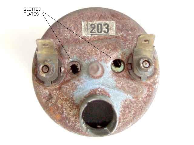
The back of a later type gauge will be very different. I couldn't find a link to a Mini or Minor later fuel gauge. This link is for a picture showing the back of a round Smiths gauge.
http://www.mgb-stuff...mages/fuel1.jpg
Look past the rust and you'll notice two holes with screwdriver slots. The back of the gauge does NOT have the additional hex nuts in slots.
Measure that sending unit and look again at the back of your new fuel gauge and let us know what you find.
Let's take a moment to talk about the later gauge system and how it works.
LATER GAUGES (post 1964)
You have the gauge connected to a 10V supply using one terminal, the other terminal goes to the insulated terminal on the sending unit. Inside the sending unit is a variable resistor. The far end of the sending unit variable resistor is hooked to earth. With 10V supplied current flows through the gauge's internal resistance wire, to the sender and to earth. The float arm changes the sending unit's resistance and "throttles" the amount of current flowing.
When the sending unit terminals are shorted out the maximum current flows through the gauge AND this causes the gauge to read FULL. Later sending units have a resistance that swings from about 240 Ohms = Empty, to 30 Ohms = Full.
It makes no difference which gauge terminal the two wires hook to. The gauge case does not have to have an earth connection.
EARLY GAUGES
Suffice it to say they are called moving magnet or moving iron gauges, they respond immediately to changes. The important distinction operationally is if you SHORT the sending unit terminals together, the gauge will read EMPTY, not full. The early sending units have a resistance that swings from about 10 Ohms = Empty, to 90 Ohms = Full. Note that this is the opposite direction and a narrower range than the later senders. It DOES matter which gauge terminal you connect the wires to. The "T" terminal comes from the (Tank) sending unit. The gauge "B" terminal comes from a switched 12V supply (Battery). As you remember, the gauge case must have a good earth connection.
You can't mix the early and late gauge system parts. It's time to make some measurements. Check the sending unit resistance. Use a bent coat hanger through the tank filler neck to lift and lower the sender. Connect a multimeter to the two lugs on the sender AND make sure no wires are connected to the sender during the test.
Look again at the back of your gauge.
The back of an early gauge (moving iron) will look like the one in this link:
http://i8.ebayimg.co...0/3c/47f4_1.JPG
Note the hex nuts moving in slots below where the wires will connect.
The back of a later type gauge will be very different. I couldn't find a link to a Mini or Minor later fuel gauge. This link is for a picture showing the back of a round Smiths gauge.
http://www.mgb-stuff...mages/fuel1.jpg
Look past the rust and you'll notice two holes with screwdriver slots. The back of the gauge does NOT have the additional hex nuts in slots.
Measure that sending unit and look again at the back of your new fuel gauge and let us know what you find.
#4
mister bridger
-
- Traders
-
- 911 posts
One Carb Or Two?
- Location: Hastings
Posted 25 February 2009 - 07:22 PM
Checked the gauge and it appears to be exactly the same as the original one and the one you refer to though with spade connections not nuts. You can see a bit of it in attached photo. Couldn't hook sender with anything so took it out and tested it on bench. I'm not very good with electrics but I think I was doing it right - No movement of the sender arm appeared to make any difference to the test though. Can you tell what sender type by looking at it?It sounds as if you have bought the wrong gauge. I know, I know you said you bought the same type as the one that broke.
Let's take a moment to talk about the later gauge system and how it works.
LATER GAUGES (post 1964)
You have the gauge connected to a 10V supply using one terminal, the other terminal goes to the insulated terminal on the sending unit. Inside the sending unit is a variable resistor. The far end of the sending unit variable resistor is hooked to earth. With 10V supplied current flows through the gauge's internal resistance wire, to the sender and to earth. The float arm changes the sending unit's resistance and "throttles" the amount of current flowing.
When the sending unit terminals are shorted out the maximum current flows through the gauge AND this causes the gauge to read FULL. Later sending units have a resistance that swings from about 240 Ohms = Empty, to 30 Ohms = Full.
It makes no difference which gauge terminal the two wires hook to. The gauge case does not have to have an earth connection.
EARLY GAUGES
Suffice it to say they are called moving magnet or moving iron gauges, they respond immediately to changes. The important distinction operationally is if you SHORT the sending unit terminals together, the gauge will read EMPTY, not full. The early sending units have a resistance that swings from about 10 Ohms = Empty, to 90 Ohms = Full. Note that this is the opposite direction and a narrower range than the later senders. It DOES matter which gauge terminal you connect the wires to. The "T" terminal comes from the (Tank) sending unit. The gauge "B" terminal comes from a switched 12V supply (Battery). As you remember, the gauge case must have a good earth connection.
You can't mix the early and late gauge system parts. It's time to make some measurements. Check the sending unit resistance. Use a bent coat hanger through the tank filler neck to lift and lower the sender. Connect a multimeter to the two lugs on the sender AND make sure no wires are connected to the sender during the test.
Look again at the back of your gauge.
The back of an early gauge (moving iron) will look like the one in this link:
http://i8.ebayimg.co...0/3c/47f4_1.JPG
Note the hex nuts moving in slots below where the wires will connect.
The back of a later type gauge will be very different. I couldn't find a link to a Mini or Minor later fuel gauge. This link is for a picture showing the back of a round Smiths gauge.
http://www.mgb-stuff...mages/fuel1.jpg
Look past the rust and you'll notice two holes with screwdriver slots. The back of the gauge does NOT have the additional hex nuts in slots.
Measure that sending unit and look again at the back of your new fuel gauge and let us know what you find.
#5
mister bridger
-
- Traders
-
- 911 posts
One Carb Or Two?
- Location: Hastings
Posted 25 February 2009 - 09:55 PM
bump
#6
dklawson
-
- TMF+ Member
-
- 10,923 posts
Moved Into The Garage
- Name: Doug
- Location: Durham, NC - USA
- Local Club: none
Posted 25 February 2009 - 10:19 PM
When I look at your second picture in your last post I see the hex nuts on the back of the gauge. That's the gauge that should work with the 10-90 Ohm early sender.
Your sender is a very rare transitional one. I've only seen one other... and that has been during the past week. See this eBay link:
http://cgi.ebay.com/...O...A1|240:1318
If the link doesn't work, look up eBay item # 230326848521
Your sender is a later bayonet mount type but it should have the EARLY resistance range (10 Ohms = Empty, 90 Ohms = Full). If you are carefully connecting your meter between the two lugs and you do NOT see any change with arm movement, the internal windings have probably burned through. I can't see clearly how you've connected the meter leads or the value displayed on the meter. Still, thanks for trying, the pictures are helpful.
Take another look at my PDF notes on the early gauges:
http://home.mindspri...ldFuelGauge.pdf
On page 1 you'll see the back of the early fuel gauge with adjusting nuts. The sending unit shown is older than yours as it has the 6 mounting screw holes. However, it should have the same resistance range as your sender. On page 4 you'll see what's inside your sending unit. If you are NOT seeing any resistance change when you move the arm on your sender you may want to open your sender up as shown in the PDF and see if you can find and fix the reason why it's not changing. You could have an open wire, a broken wire, a dirty connection between the arm and housing, loose or damaged wiper arms....
I still think your long term easy fix is to buy a later gauge AND matching later sender along with a solid state stabilizer from Jupitus. In a few minutes you'll have a working gauge system that uses parts that are still available.
#7
mister bridger
-
- Traders
-
- 911 posts
One Carb Or Two?
- Location: Hastings
Posted 26 February 2009 - 12:09 AM
I guess thats what I'll have to do though I was trying to retain the silver face instruments original to the car. I have managed to detach the front from the old broken gauge so will try to marry that up with the later gauge I have, along with the stabilizer and I'll order a later type sender. Frustrating that I've not been able to get the original parts working though!When I look at your second picture in your last post I see the hex nuts on the back of the gauge. That's the gauge that should work with the 10-90 Ohm early sender.
Your sender is a very rare transitional one. I've only seen one other... and that has been during the past week. See this eBay link:
http://cgi.ebay.com/...O...A1|240:1318
If the link doesn't work, look up eBay item # 230326848521
Your sender is a later bayonet mount type but it should have the EARLY resistance range (10 Ohms = Empty, 90 Ohms = Full). If you are carefully connecting your meter between the two lugs and you do NOT see any change with arm movement, the internal windings have probably burned through. I can't see clearly how you've connected the meter leads or the value displayed on the meter. Still, thanks for trying, the pictures are helpful.
Take another look at my PDF notes on the early gauges:
http://home.mindspri...ldFuelGauge.pdf
On page 1 you'll see the back of the early fuel gauge with adjusting nuts. The sending unit shown is older than yours as it has the 6 mounting screw holes. However, it should have the same resistance range as your sender. On page 4 you'll see what's inside your sending unit. If you are NOT seeing any resistance change when you move the arm on your sender you may want to open your sender up as shown in the PDF and see if you can find and fix the reason why it's not changing. You could have an open wire, a broken wire, a dirty connection between the arm and housing, loose or damaged wiper arms....
I still think your long term easy fix is to buy a later gauge AND matching later sender along with a solid state stabilizer from Jupitus. In a few minutes you'll have a working gauge system that uses parts that are still available.
#8
mister bridger
-
- Traders
-
- 911 posts
One Carb Or Two?
- Location: Hastings
Posted 26 February 2009 - 12:15 AM
That sender has exactly the same markings as mine..
Your sender is a very rare transitional one. I've only seen one other... and that has been during the past week. See this eBay link:
http://cgi.ebay.com/...O...A1|240:1318
#9
dklawson
-
- TMF+ Member
-
- 10,923 posts
Moved Into The Garage
- Name: Doug
- Location: Durham, NC - USA
- Local Club: none
Posted 26 February 2009 - 01:02 AM
Well don't give up yet.
I thought the silver faced gauges were exclusive for the really early Minis and weren't in use by 1964. I can understand why you want to keep it looking the way it is. The silver faced gauges have a very unique look.
OK, so before giving up, confirm for me what the sending unit is doing on the bench AND what happens if you connect the green/black wire in the boot to earth. (With the ignition on and the green/black wire disconnected the gauge should read Full. With the ignition on and the green/black wire earthed, the gauge should read Empty or below Empty). We've already talked at length about what the sending unit should be doing, just confirm for me how you've connected the meter probes and what if anything is happening when you test the sending unit.
If the green/black wire tests give the gauge action I described above then the gauge and wiring are OK. Your next step once you know the gauge is OK would be to open up that sending unit. If it's not changing resistance when you move the arm... you have nothing to loose by opening it up, cleaning it, and (if possible) repairing any damage you find.
EDIT: I believe I mentioned this earlier when discussing problems with the early sending units. The wipers for the variable resistor are inside the back cover of the sending unit and are attached to the float arm. The float arm makes its earth connection through the bushing supporting the arm when it pivots. Dirt or varnish in the bushing can cause problems just as mechanical damage to the wiper and resistance windings. Again, it won't hurt to look inside if you're not measuring resistance changes.
You certainly could move the gauge face from one fuel gauge to another and it shouldn't be too hard. I assume you saved the gauge where the nut broke off the back and that gauge will be your face donor.
You could always bid on the eBay sender I posted the link to. I only remember there being one bid on it.
Edited by dklawson, 26 February 2009 - 01:07 AM.
#10
dklawson
-
- TMF+ Member
-
- 10,923 posts
Moved Into The Garage
- Name: Doug
- Location: Durham, NC - USA
- Local Club: none
Posted 26 February 2009 - 01:28 AM
Rather than edit my last post (again) I thought it would be best to post the following information all by itself.
I don't remember if I provided the following link in your last thread or not. Please visit this link and read through the subsequent pages. (Use the arrows at the bottom of the page to move forward to subsequent pages).
http://www.mgaguru.c...ctric/fg_01.htm
The link above is for Barney Gaylord's web site for the MGA. The gauge system on the MGA is virtually identical to that used on the early Mini apart from the resistance range of the sending unit. Barney will walk you through how the gauge works, show you pictures of what's inside, and finally show you how to calibrate the gauge.
I keep coming back to your first post above where you said shorting the sending unit terminals moves the needle to full. This is the behavior one expects of the later gauge system, not the early gauges so I am very confused. Is there any chance you put the green/black wire on the gauge's "B" terminal instead of its "T" terminal?
#11
mister bridger
-
- Traders
-
- 911 posts
One Carb Or Two?
- Location: Hastings
Posted 26 February 2009 - 10:59 AM
Well I HATE to admit but I give up! Taken the sender unit off again and there is no response on the meter when you move the arm. And lucky old me I have the only one in Christendom that's not serviceable - spot welded together rather than screws or tabs. Also tried the tests on the wiring suggested and it doesn't seem to do one thing or the other consistently. Only bit of luck I've had is transferring the silver face of the broken gauge to the later one.
Will order the later type sensor today. Can someone just explain how to wire in the voltage stabiliser? 3 wires red black and white.
Will order the later type sensor today. Can someone just explain how to wire in the voltage stabiliser? 3 wires red black and white.
#12
midridge2
-

- Members
-
- 1,794 posts
Camshaft & Stage Two Head
- Location: north east england
Posted 26 February 2009 - 11:42 AM
taking into account you said your not good with electrics what settings did you have your multimeter on when you tested the sender unit on the bench, remember you have to have electric going through the sender unit to get readings.
#13
mister bridger
-
- Traders
-
- 911 posts
One Carb Or Two?
- Location: Hastings
Posted 26 February 2009 - 12:58 PM
Aaaah! I just put an ohmeter across the teminals! So should I have 12v feed to one and then measure across terminals or what?taking into account you said your not good with electrics what settings did you have your multimeter on when you tested the sender unit on the bench, remember you have to have electric going through the sender unit to get readings.
#14
Jupitus
-

- Members
-
- 1,479 posts
One Carb Or Two?
- Local Club: Breathemini
Posted 26 February 2009 - 01:12 PM
Well I HATE to admit but I give up! Taken the sender unit off again and there is no response on the meter when you move the arm. And lucky old me I have the only one in Christendom that's not serviceable - spot welded together rather than screws or tabs. Also tried the tests on the wiring suggested and it doesn't seem to do one thing or the other consistently. Only bit of luck I've had is transferring the silver face of the broken gauge to the later one.
Will order the later type sensor today. Can someone just explain how to wire in the voltage stabiliser? 3 wires red black and white.
Black = Earth
Red = Ignition fed 12V
White = Stabilised 10V - Connect to +ve terminal on gauge

#15
dklawson
-
- TMF+ Member
-
- 10,923 posts
Moved Into The Garage
- Name: Doug
- Location: Durham, NC - USA
- Local Club: none
Posted 26 February 2009 - 01:25 PM
You posted a picture of you using the meter and it looked OK. You had the meter set to Ohms, you had the red and black probes in the correct meter sockets. I couldn't tell where the meter leads were being held against the sender but one lead should be on one sender post, one meter lead on the other.
At the extreme limits of travel the wiper inside the sender MAY be off the resistance coil. If that's true, the meter will read infinite Ohms instead of somewhere between 0 and 100 Ohms. On threaded posts like that I put ring terminals on them and stick the meter probes into the wire hole in the ring terminals. It's easier than holding things in place while you try to move the float arm.
OK, so let's say you give up and go for the later gauge conversion. It sounds like you're well under way with the gauge face. Turning our attention to the sending unit, you need only to put the new one in the hole in the tank and secure as normal. Your old harness will have ring terminals for the old sender. You'll need to replace those with female spade lugs to work with the new sender.
At the front of the car there are a couple of things you'll need to do. The later (resistance wire type) fuel gauge does NOT care which wire goes where. Connect the green/black wire from the sender to one gauge terminal. If you buy the voltage stabilizer from Jupitus, he'll have to tell you which wire colors he used, I can't. On the OLD gauge there would have been two green wires on the "B" terminal. What you will need to do is join those two wires together AND join them to the stabilizer's input terminal. (I am not a big fan of cutting wire ends off and splicing them together. Electronic shops may have spade type connector parts that will let you join multiple wires. I would find one of those and make sure it's insulated when you're done. This will allow you go change back at a future date if you change your mind). The stabilizer will have an earth connection wire, be sure to use it. Finally, the output wire from the stabilizer will go to the remaining terminal on the fuel gauge. That's it, you're done.
You could still bid on the sending unit in the U.S. However, the way you're describing the gauge's behavior doesn't give me a lot of confidence in it. As I mentioned in your previous thread DO NOT throw those old parts out. I know you said that the old sending unit is spot welded closed. It can still be worked on by someone who really wants it. If you don't want to keep the old bits, post a "free to good home" message on the Specialist Mini Forums for the early cars:
http://specialistmin...ku.com/forums/5
Were I in the U.K. I'd pick the parts up from you just to see how they differ from the early and later components.
Don't let this thread end here. Be sure to post updates of your progress and obviously feel free to ask more questions.


1 user(s) are reading this topic
0 members, 1 guests, 0 anonymous users


