Hi everyone,
I need to know the current rating on the wire used on the ignition barrel as I am replacing it with a push button circuit and a few relays to take the place of the key switch.
Any help would be much appreciated,
Thanks
Seb


Ignition Cable Rating
Started by
sebseb8
, Dec 09 2011 10:07 AM
13 replies to this topic
#1

sebseb8
-
- TMF+ Member
-

- 92 posts
Stage One Kit Fitted
- Location: Stroud, Gloucestershire
Posted 09 December 2011 - 10:07 AM
#2
sebseb8
-
- TMF+ Member
-
- 92 posts
Stage One Kit Fitted
- Location: Stroud, Gloucestershire
Posted 09 December 2011 - 10:46 PM
Anyone got any idea?
#3
grahama
-

- Members
-
- 2,442 posts
Up Into Fourth
- Location: Warrington
- Local Club: None in my area !!
Posted 09 December 2011 - 11:17 PM
No, waiting for a reply myself. However, if you have the cable take it to an auto electrician and ask there, they will at least be able to let you know the mm square of the cable and if it has any special properties as an ignition cable.
Graham
Graham
#4
sebseb8
-
- TMF+ Member
-
- 92 posts
Stage One Kit Fitted
- Location: Stroud, Gloucestershire
Posted 13 December 2011 - 11:14 PM
No, waiting for a reply myself. However, if you have the cable take it to an auto electrician and ask there, they will at least be able to let you know the mm square of the cable and if it has any special properties as an ignition cable.
Graham
Thanks Graham. If I do manage to find out I shall let you know.
Seb
#5
Dan
-

- TMF+ Member
-
- 21,354 posts
On Sabbatical
Posted 13 December 2011 - 11:48 PM
How exactly are you going about this? It would be extremely dangerous, and illegal, to adapt the car in such a way that it was possible for the steering lock to be engaged with the engine running. Also there are legal requirements regarding immobilisation that the steering lock satisfies, which is why they became standard fit after originally being an option.
If you are replacing a lot of the functions of the switch with relays then the actual push button won't be doing much. Just make sure the cables, relays and all the components in each individual power supply circuit are capable of running the equipment on that circuit with a healthy margin for safety. You don't say what Mini it is, the electrical system changed probably more often than anything else over the years. Without relays fitted, under most of the standard wiring layouts the ignition switch is carrying all of the current through the system apart from battery charging and headlights so it's pretty chunky cable. Count the strands in it, it's probably 65 strand cable, 4.5 mm. Rated at 35 amps depending on installation.
If you are replacing a lot of the functions of the switch with relays then the actual push button won't be doing much. Just make sure the cables, relays and all the components in each individual power supply circuit are capable of running the equipment on that circuit with a healthy margin for safety. You don't say what Mini it is, the electrical system changed probably more often than anything else over the years. Without relays fitted, under most of the standard wiring layouts the ignition switch is carrying all of the current through the system apart from battery charging and headlights so it's pretty chunky cable. Count the strands in it, it's probably 65 strand cable, 4.5 mm. Rated at 35 amps depending on installation.
#6
sebseb8
-
- TMF+ Member
-
- 92 posts
Stage One Kit Fitted
- Location: Stroud, Gloucestershire
Posted 14 December 2011 - 10:51 AM
Dan,
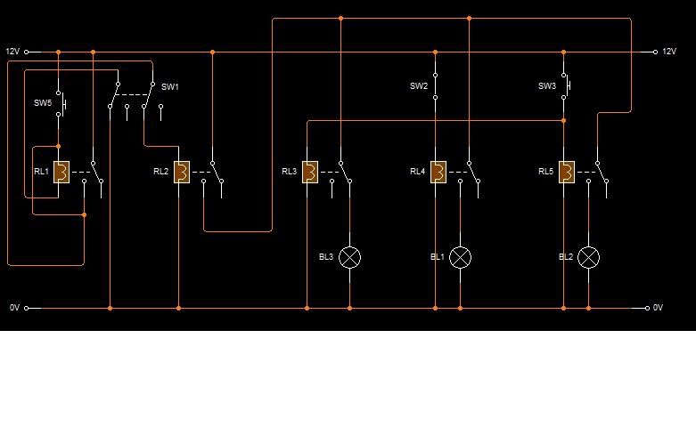
There is a RFID circuit which when activated will supply the first relay, this relay will latch and supply a second relay which will supply power to the common points on the next three relays, the next relay is the controller of the auxiliary circuit, power is then supplied to a fourth relay which will control the ignition circuit, this circuit is only active though when a switch is on, when the push button is pressed this dis-engages the auxiliary circuit and a fifth relay supplies power to the starter solenoid, when released power is then re-enstated to the auxiliary circuit. To turn the engine off a switch is moved to the off position which leaves the auxiliary circuit running, to turn this off a second switch is also moved to the off position. In the diagram I've attached the auxiliary switch is sw1, ignition switch is sw2 and the engine start button is sw3, aux relay is RL3, ignition relay is RL4 and starter relay is RL5.
Please let me know if im going to have problems with this,
Thanks,
Seb
#7
phil hill
-

- TMF+ Member
-
- 616 posts
Super Mini Mad
- Location: Lincoln, UK
Posted 14 December 2011 - 11:11 AM
Looks over complicated to me, what are you actually trying to achieve ??
Phil.
Phil.
#8
sebseb8
-
- TMF+ Member
-
- 92 posts
Stage One Kit Fitted
- Location: Stroud, Gloucestershire
Posted 14 December 2011 - 11:35 AM
I just wanted to replace the boring old key switch with something a bit more impressive like a race start but for the road. Plus I'm doing electronics at college so just wanted a project to work on
Seb
Seb
Edited by sebseb8, 14 December 2011 - 11:36 AM.
#9
Guess-Works.com
-

- Traders
-
- 19,838 posts
Gearbox Guru
- Local Club: Rugby Classic Mini Owners Club
Posted 14 December 2011 - 12:36 PM
What happens if one of the 'charged' relays blows while you are driving ?
#10
sebseb8
-
- TMF+ Member
-
- 92 posts
Stage One Kit Fitted
- Location: Stroud, Gloucestershire
Posted 14 December 2011 - 01:26 PM
What happens if one of the 'charged' relays blows while you are driving ?
Guess works,
Since the only relay that is charged while driving is the ignition circuit one would replacing this with a switch be ok?
Seb
#11
phil hill
-
- TMF+ Member
-
- 616 posts
Super Mini Mad
- Location: Lincoln, UK
Posted 14 December 2011 - 02:02 PM
Ok, assuming by RFID you mean some sort of wireless transponder deal like a modern car with the security chip in the key to remote "activate" the whole system then that sounds like a great project. Unfortunately I completed my electronics degree about 20 years ago now (can't believe I just admitted that lol !!) so I'm not current with that technology but I get the point. In terms of using some relays and some hard-wired logic to get what you want then ok, fair enough, but I think you are getting too complicated. If you have the ability to do the RFID but then use the same micro-controller to drive some outputs to active a couple of relays for auxillary and ignition circuits, then another for your starter request. If you simply want to replace or run in parallel with the existing key for a starter button then go for that.
Phil.
Phil.
#12
sebseb8
-
- TMF+ Member
-
- 92 posts
Stage One Kit Fitted
- Location: Stroud, Gloucestershire
Posted 14 December 2011 - 10:41 PM
Ok, assuming by RFID you mean some sort of wireless transponder deal like a modern car with the security chip in the key to remote "activate" the whole system then that sounds like a great project. Unfortunately I completed my electronics degree about 20 years ago now (can't believe I just admitted that lol !!) so I'm not current with that technology but I get the point. In terms of using some relays and some hard-wired logic to get what you want then ok, fair enough, but I think you are getting too complicated. If you have the ability to do the RFID but then use the same micro-controller to drive some outputs to active a couple of relays for auxillary and ignition circuits, then another for your starter request. If you simply want to replace or run in parallel with the existing key for a starter button then go for that.
Phil.
Phil,
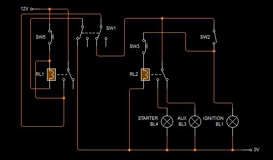
I have re-worked the circuit down to just two relays, one to latch and control power and the other to switch between the auxiliary and starter circuit. I did think about using the micro-controller as the driver for the relays but I did think along the same lines as guess work for that and wasn't sure what would happen if something happened with the program or something similar. So my question to you is do you think the circuit I've got it down to is more reasonable?
Thanks,
Seb
#13
Brams96
-

- Members
-
- 2,308 posts
Up Into Fourth
- Local Club: Kentish Mini Club
Posted 14 December 2011 - 10:54 PM
Seems over complicated to me. Normal operation is get in car, turn key, drive, turn key off. Yours seems like get in, turn on switch 1, turn on switch 2 then push start button, drive, turn off switch 1, turn off switch 2. It's not like your in a helicopter or aeroplane cockpit with lots of switches, it's a mini. Why not come up with something to immobilise your car using a series of latching relay's, that would b more practicle.
#14
sebseb8
-
- TMF+ Member
-
- 92 posts
Stage One Kit Fitted
- Location: Stroud, Gloucestershire
Posted 14 December 2011 - 11:09 PM
Seems over complicated to me. Normal operation is get in car, turn key, drive, turn key off. Yours seems like get in, turn on switch 1, turn on switch 2 then push start button, drive, turn off switch 1, turn off switch 2. It's not like your in a helicopter or aeroplane cockpit with lots of switches, it's a mini. Why not come up with something to immobilise your car using a series of latching relay's, that would b more practicle.
There is an immobiser in the circuit, just not on the circuit digram. I have an RFID circuit that once active will cause the first relay to latch on, and this circuit to work


1 user(s) are reading this topic
0 members, 1 guests, 0 anonymous users


