Help with wiring an FIA style master switch please.
How does the little - is it a choke? - go in the circuit? I understand that it's purpose is to protect the alternator and to prevent engine run on, but how and where. In my previous track day car I wired the ignition separately and alway killed that circuit before turning off the master. Seemed to work well but I want to do this project 'properly' so advice welcomed.....
Bob


Master Switch Wiring
Started by
Old Bob
, Jan 31 2013 05:35 PM
7 replies to this topic
#1

Old Bob
-
- Noobies
-

- 825 posts
TMF Menber Passed On R.I,P
- Location: South Hams
Posted 31 January 2013 - 05:35 PM
#3
tiger99
-

- Members
-
- 8,584 posts
Crazy About Mini's
- Location: Hemel Hempstead
Posted 31 January 2013 - 06:11 PM
You should have a diode which bypasses the switch, so that the alternator can still charge the battery with the switch off, but the battery can't continue to drive the rest of the car. It needs to be a very beefy diode, as it might be momentarily carrying full alternator current if someone opens the switch with the engine running. The resistor is not an effective substitute. It is presumably switched in by a contact on the switch as the main contact opens, however simultaneous contact operation is impossible, and if the main contact opens first, the alternator may still be damaged, while if the switch is operated slowly and the diode comes into circuity when the main contact is still closed, nearly 5 amps is going to flow through that 3 ohm resistor, at 14.4V, so the 11 watt resistor is going to experience nearly 70 watts. If the switch is operated too slowly, the resistor will fail, giving no indication, and next time the switch is used, it will be the alternator that fails.
The diode is far less troublesome, but it wants to be rated at 50V or more, say 10A continuous, 100A peak, to give it a decent safety factor and therefore a long life. It may need a heatsink. but possibly not, depending on how quickly the engine stops, and the alternator stops generating, when the switch is opened.
The diode is far less troublesome, but it wants to be rated at 50V or more, say 10A continuous, 100A peak, to give it a decent safety factor and therefore a long life. It may need a heatsink. but possibly not, depending on how quickly the engine stops, and the alternator stops generating, when the switch is opened.
#4
dklawson
-

- TMF+ Member
-
- 10,923 posts
Moved Into The Garage
- Name: Doug
- Location: Durham, NC - USA
- Local Club: none
Posted 31 January 2013 - 06:36 PM
You should have a diode which bypasses the switch, so that the alternator can still charge the battery with the switch off, but the battery can't continue to drive the rest of the car.
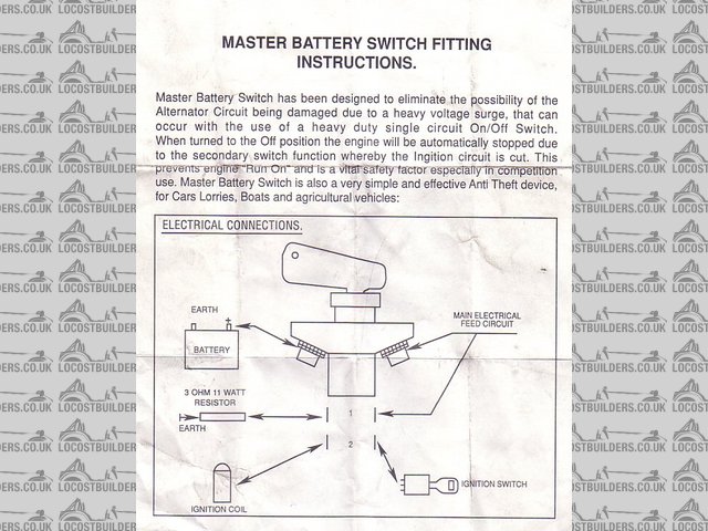
That is not my understanding. The FIA switch has three sets of contacts. When the switch is off it is supposed to separate the battery from the alternator output, kill the engine by breaking the current flowing through the coil, and dump the alternator output to earth (through the power resistor). The purpose of the switch is to completely separate the alternator output from the battery when the switch is turned to the off position so you don't want a diode to bypass it...at least not for racing purposes.
I have no argument with the switch time statements but if this is for racing purposes it should be wired to meet the appropriate sanctioning body standards as described in the switch literature. Keep in mind that this is NOT the way you normally turn the engine off, it is for corner workers responding to an emergency. That high-Wattage surge will be experienced for a fraction of a second, not continuously.
EDIT: Sorry, I did not address Rally1380's question.
The threaded power terminal shown on the right of the schematic should have cables for the starter motor (solenoid supply side) and alternator output attached.
A smaller jumper wire goes from that threaded terminal down to one side (either side) of the switch contacts labeled "1" in the schematic.
A wire from one side of the power resistor connects to the other terminal for contact pair "1".
A wire from the other side of the power resistor goes to earth.
When you turn the key to "OFF" contact pair "1" closes and the alternator output passes through the resistor, and on to earth.
The current flowing through the ignition coil must pass through the contacts labeled "2".
When the switch is in the "ON" position, contact pair "2" is closed and coil current can pass.
When the switch is set to "OFF" the coil current path is broken and this disables the ignition spark.
Without the spark, the engine comes to a stop very quickly and the alternator output quickly dumps to earth through the power resistor during this coast-down period.
Edited by dklawson, 31 January 2013 - 06:47 PM.
#5
Old Bob
-
- Noobies
-
- 825 posts
TMF Menber Passed On R.I,P
- Location: South Hams
Posted 31 January 2013 - 07:06 PM
Thanks Guys.
Bob
Bob
#6
rally1380
-

- Members
-
- 1,893 posts
Camshaft & Stage Two Head
- Location: Cheshire
Posted 31 January 2013 - 09:24 PM
DKLAWSON.....superb answer yet again.
The "2" pair......which side of coil and how do you link it into the ignition switch?
The "2" pair......which side of coil and how do you link it into the ignition switch?
#7
dklawson
-
- TMF+ Member
-
- 10,923 posts
Moved Into The Garage
- Name: Doug
- Location: Durham, NC - USA
- Local Club: none
Posted 31 January 2013 - 10:32 PM
There are a couple of ways to wire the ignition switch depending on whether you want to fuse the circuit or not.
(I have not included the start push-button below).
Without fusing...
With fusing:
I don't believe fusing the ignition circuit is required by most sanctioning bodies but double check to be sure. Simple ignition systems for street cars are typically not fused. Personally, I like fuses.
(I have not included the start push-button below).
Without fusing...
- Install a jumper wire between the threaded right hand terminal on the FIA switch to one of the contact "2" terminals.
- Run a wire from the remaining contact "2" terminal to your ignition switch.
- Run a wire from the other ignition switch terminal to coil (+)
With fusing:
- Run a large feed wire from the threaded right hand terminal on the FIA switch to your fuse block.
- Run a wire from one of those fuse terminals to your ignition switch.
- Run a wire from the remaining ignition switch terminal to one of the contact "2" terminals.
- Run a wire from the remaining contact "2" terminals to coil (+)
I don't believe fusing the ignition circuit is required by most sanctioning bodies but double check to be sure. Simple ignition systems for street cars are typically not fused. Personally, I like fuses.
#8
tiger99
-
- Members
-
- 8,584 posts
Crazy About Mini's
- Location: Hemel Hempstead
Posted 01 February 2013 - 01:12 PM
Doug, yes if it is for meeting safety regulations, I would agree with you. It does not matter so much if the alternator is killed in the process, and in any case they will be operating the switch quickly and decisively, which helps. But there are other switches available for normal road cars which do have the diode, and are mostly used for deterring thieves, although they have other benefits too, such as avoiding residual current drain if the car is not in regular use.
As you suggest, not to be used in non-emergency situations for stopping the engine, although I fear that some people might do that....


1 user(s) are reading this topic
0 members, 1 guests, 0 anonymous users


