Jump to content


Photo
- - - - -

Radiator Switch/electric Fan/relay. How Is It Wired?


  • Please log in to reply
4 replies to this topic

#1 Pigeonto

Pigeonto

    One Carb Or Two?

  • Members
  • PipPipPipPipPipPipPip
  • 973 posts
  • Location: Nr Colchester Essex
  • Local Club: ISMOC

Posted 12 July 2013 - 11:01 AM

Simple electrics I assumed.12v goes to one of the radiator thermo-switch connections,green and white.The other is black.Connect them together,the relay goes and the fan runs.But if I put a separate 12v supply up that same black wire the relay doesnt energise and too many amps are being drawn (over 10) so I have to stop. How does it work??

Also if I put the thermo-swich in boiling water should it then open and make a circuit?

I want to run a switched 12v supply(toggle switch in the car) to a trigger on the fan relay but if I do that to any of the 4, it doesnt energise.

I dont get it,hopefully some one does.


#2 lrostoke

lrostoke

    Crazy About Mini's

  • Members
  • PipPipPipPipPipPipPipPipPipPip
  • 6,923 posts
  • Location: Maybank, Staffordshire
  • Local Club: none

Posted 12 July 2013 - 11:10 AM

Your main problem is you are confusing what the thermocouple does...it supplies an earth to the relay no a positive 12v supply.

This is why when you connect to the black wire you get high current draw, your are dead shorting.


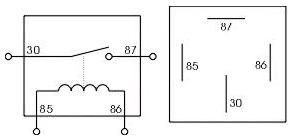
see diagram


terminal 30 is main battery power into relay

terminal 87 goes to the fans positive terminal     ..note 30 and 87 can be reversed


terminal 85 is lower ampage 12v supply

terminal 86 is earth in the case of a thermocouple it will be connected to one wire on that, the other wire on the thermocouple should be earth


again terminals 85 and 86 can be reversed


also attached diagram from Haynes parts 38 is switch , parts 30 is fan


Easiest way add a seperate switch to overide the thermocouple is connect one side of the switch to a good earth, then run a wire from the other switch terminal and connect it to the light green/white wire off the thermocouple...This will fool the system into thinking the thermocouple as closed and will energise the relay


4-pin-automotive-relay.jpg

Attached Files


Edited by lrostoke, 12 July 2013 - 11:23 AM.


#3 Pigeonto

Pigeonto

    One Carb Or Two?

  • Members
  • PipPipPipPipPipPipPip
  • 973 posts
  • Location: Nr Colchester Essex
  • Local Club: ISMOC

Posted 12 July 2013 - 12:00 PM

AHA.Thankyou. I started to consider this must use a switched earth  but the thought of 12v coming to the thermocouple and it opening up when hot to then send that 12v to earth did me. Where does that 12v down the green/white go to when the switch closes?  

Anyway,no problen with what you suggest,sounds like a plan, will do that


Edited by Pigeonto, 12 July 2013 - 12:02 PM.


#4 Ethel

Ethel

    ..is NOT a girl!

  • TMF Team
  • PipPipPipPipPipPipPipPipPipPipPip
  • 26,077 posts
  • Local Club: none

Posted 12 July 2013 - 12:16 PM

If you're measuring 12v at the open thermic switch, that's correct. Voltage is also called "potential difference", like water in the header tank above your toilet. When you connect your voltmeter you allow a vary small current to flow through the meter to measure the electrical equivalent of the gravitational energy the water would release in running down the pipe into your bog.


#5 Pigeonto

Pigeonto

    One Carb Or Two?

  • Members
  • PipPipPipPipPipPipPip
  • 973 posts
  • Location: Nr Colchester Essex
  • Local Club: ISMOC

Posted 12 July 2013 - 12:38 PM

I see. So that 12v measured is a merest trickle,no amps behind it,no power just sort of  'there' and not 'real' 12v. (Layman's logic :shy: ) Have tried earthing out both the thermocouple/thermic switch wires to the block at same time and sure enough the relay energises.As it does when like Steve suggests an earth is supplied to that spade terminal on the relay :highfive:  But the switch itself wont close even at boiling point so must be goosed


1 user(s) are reading this topic

0 members, 1 guests, 0 anonymous users