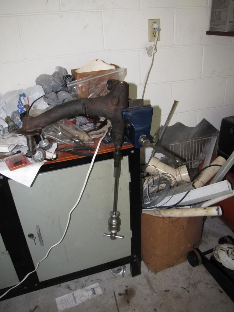
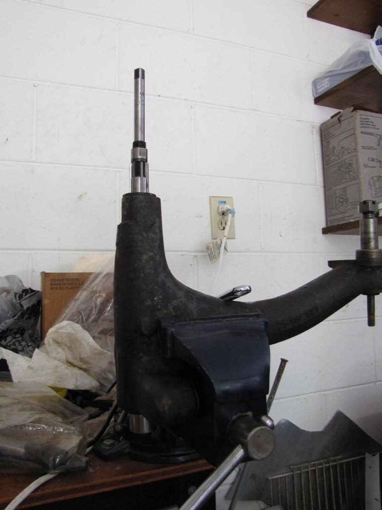
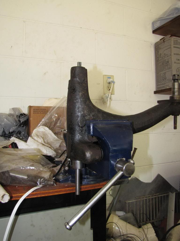
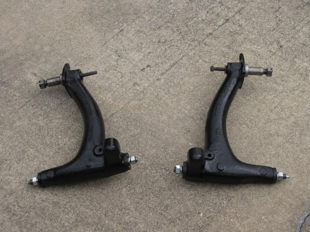
For a while, I have been planning on redoing at least one of my radius arms. But the planning got interrupted last year with a blown differential that created a whole new set of lessons to be learned. I had already bought the tools I needed a long time ago to remove and ream the bushing of the radius arm. That was a good thing since the internal bearing puller came in very handy when replacing the bearing and races on the transfer case. Anyway, recently I obtained a used set of radius arms from a TMF member to practice with and redo with new brakes so by the time I get them to the car it is hopefully just a swap of already built up radius arms.
This is not necessarily the best way to redo the radius arms, but it is how I did it. Hopefully, it will be of some help to somebody.
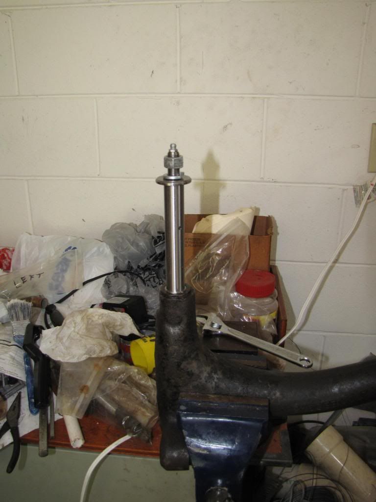
On that note, the shafts came out of radius arms with not much effort and they had some pitting and corrosion on the bushing end. It looked like lack of grease. However the bearing ends did not look bad and had enough grease. This was not an issue since I was going to install a rebuild kit.
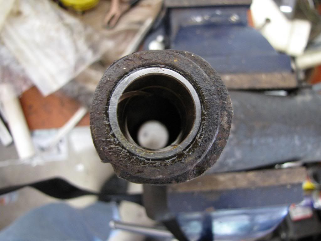
I reinstalled the shafts and degreased and pressure washed the arms externally. Big mistake. By the time I got back to remove the shafts, bushings and bearings, then the right shaft was very difficult to remove. The bearing came out fine with the internal bearing puller.
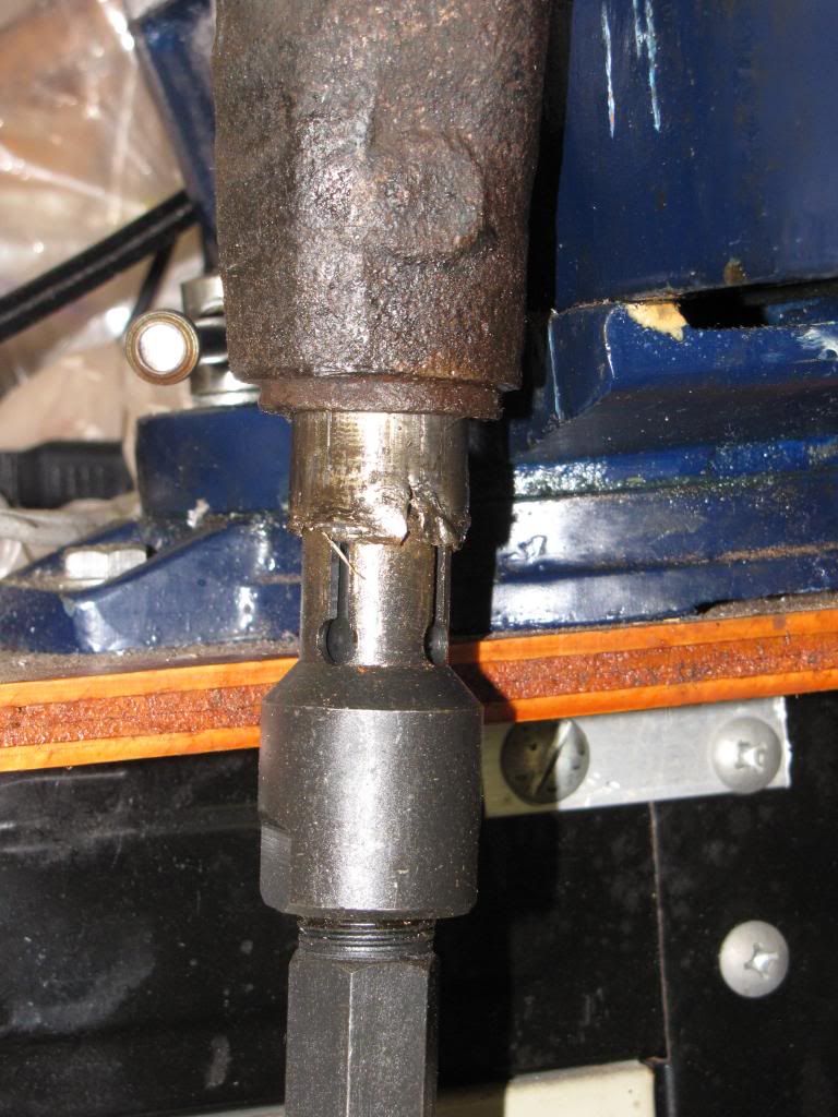
However, the bushing would not come out. I had to cut some axial slots on the bushing with the tip of a hack saw to weaken it and it finally came out with the puller. The puller needs the aid of gravity, that was the lesson learned with the transfer case. Either that or I am getting too old and weak to make it work in any other direction.
When I tried to remove the left shaft, it was really stuck. Making a long story short, after a day of soaking in penetrating oil, the shaft started coming out with a lot of hammering and the bushing still stuck to it.
The lesson learned was; remove the old shaft, bearing and bushing before pressure washing the radius arm or everything will rust in place.
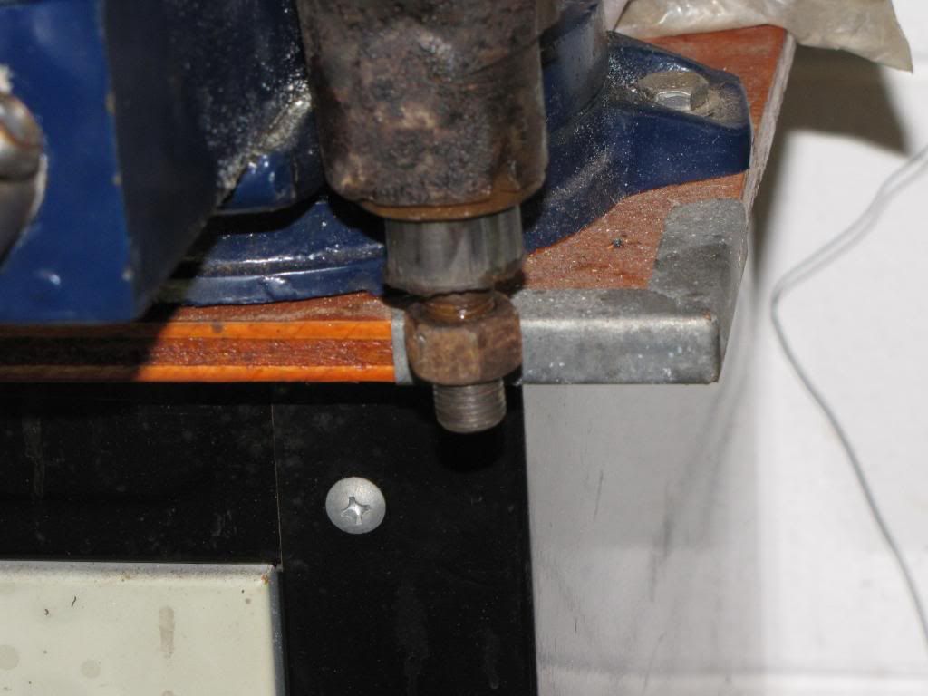
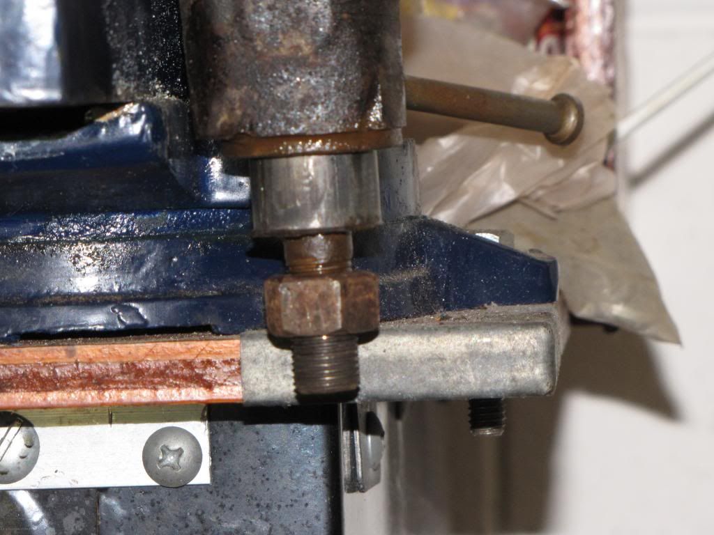
For the installation, I started with the bushing. First I greased the inside of the arm bore and the outside of the bushing. I used a socket and a two pound hammer to drive it in.
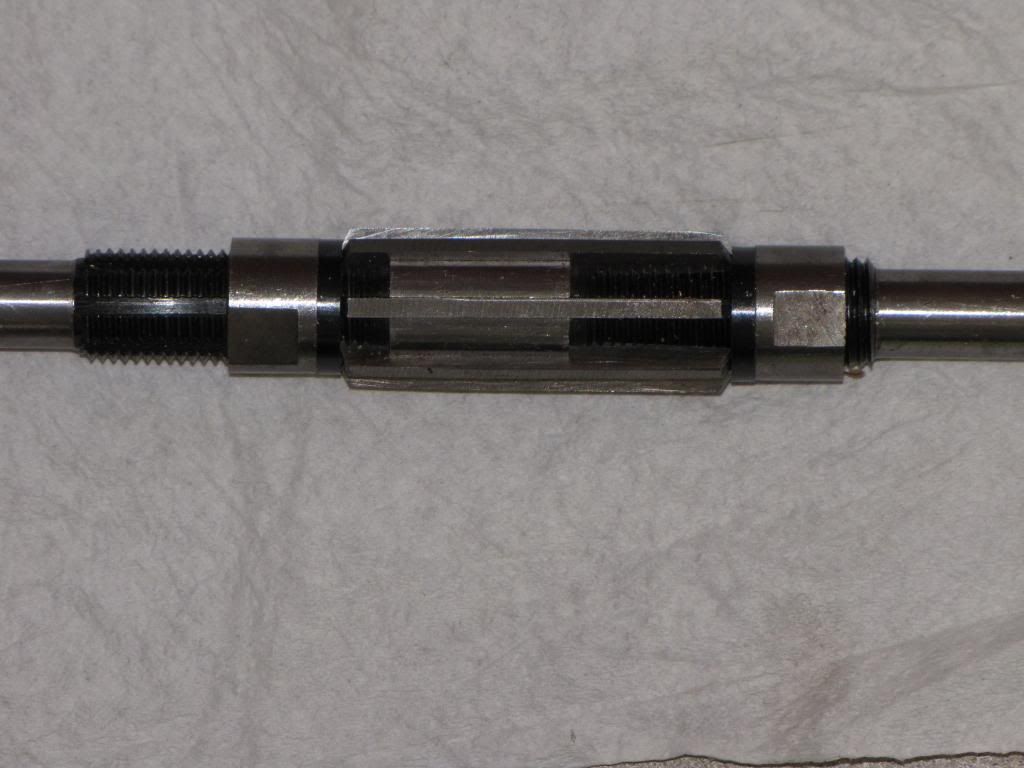
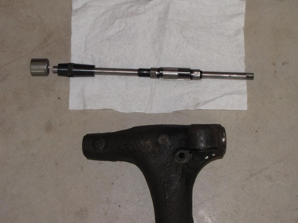
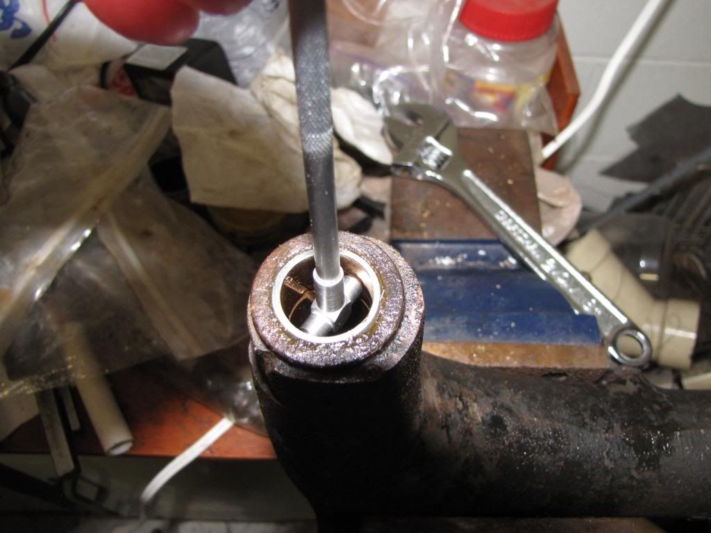
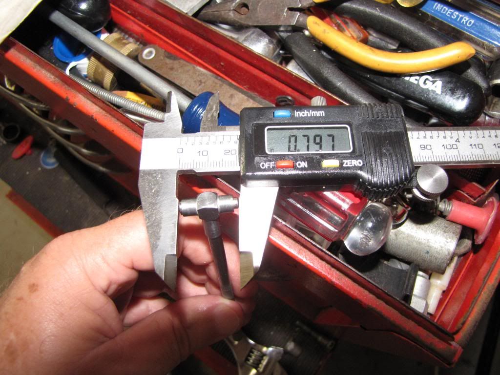
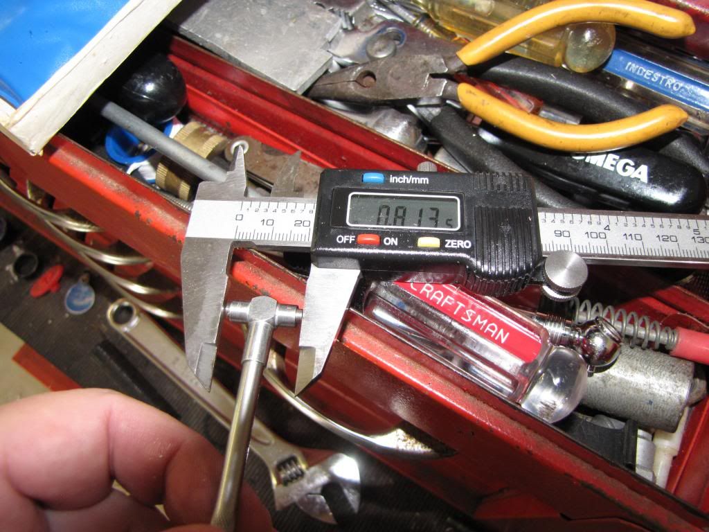
Now, I needed to come up with the scheme to use the adjustable piloted reamer which was originally used for reaming the king pin bushings of a 1950’s Chevy. When I bought the reamer from Ebay, I was looking for a piloted reamer that would go up to 13/16 of an inch. This one had the pilot and the diameter. I was not sure of the length. When I got it, the length seemed OK but one thing I was not counting on was the number of cutter heads was not even. So, the diameter could not be set by measuring directly with a caliper or micrometer across the cutter heads.
The lesson learned was; if you buy an adjustable reamer make sure it has an even number of cutter heads. Or use some scrap of soft metal, drill and ream it to the proper size to use as a gage before reaming the radius arm bushing.
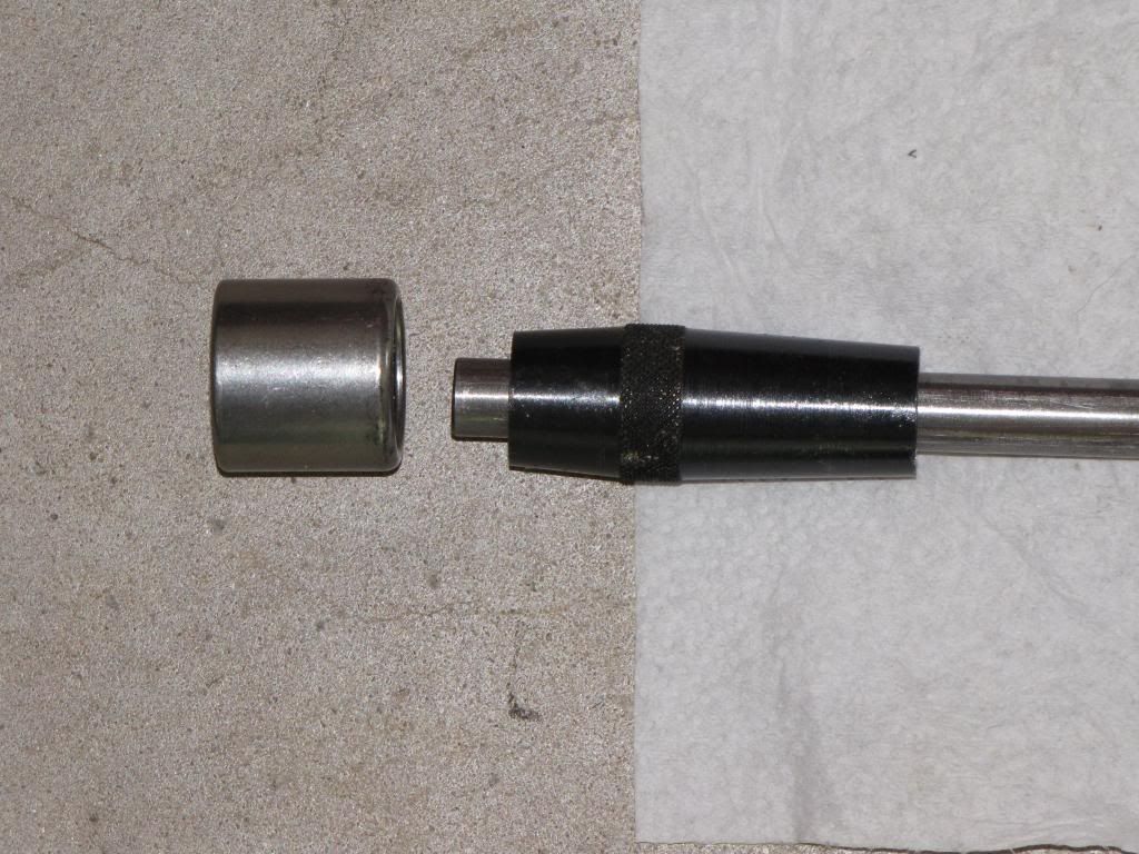
The double tapered pilot was too small to fit directly inside the radius arm. However, if partially inserted an old bearing the fit of the taper was perfect. With a couple of taps on the sides the bearing would comeback out easily. So, again gravity would do some of the work by allowing the taper to center itself in the bearing and when driving the reamer from above.
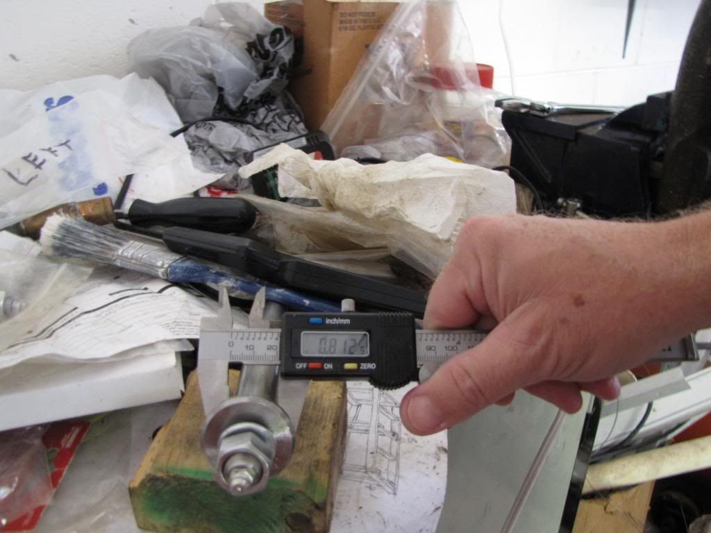
I decided to do a first pass with pretty much the initial diameter of the bushing to measure a diameter then turn the adjustment by 1/2 turn for the second cut and estimate how many thousands of an inch per turn the diameter of the cutter would increase. It was about 0.010 inch per turn. I did this a couple of times until I got to the final diameter and the shaft went in with no play.
The other side took longer for some weird reason but it got done too. Now, let’s hope that car cooperates for the installation whenever I am ready…..
Edited by xrocketengineer, 18 August 2013 - 01:19 PM.


