Jump to content


Photo
- - - - -

Wiring Issue For Tachometer, Coil, Solenoid


  • Please log in to reply
18 replies to this topic

#1 unique_name

unique_name

    Learner Driver

  • Noobies
  • PipPip
  • 17 posts
  • Location: Outback

Posted 26 August 2013 - 11:53 AM

Hi Mini Guru's


I'm have a number of questions regarding my mini and would love some help. I have a issue with the wiring of my 1972 Clubman and getting it to start. So this is what I have done so far.


- So I started at the battery and everything is fine. 

- Next checked the solenoid. It was due to a replacement so a new one has been installed. Engine kicks over by bridging the points. 

- I had been cleaning up the wiring behind the dash due to previous owner doing a crappy job and I thought the alarm system might be playing up. .So spent a couple of weeks checking that. Seems to be fine. I have done a basic wiring diagram to show the setup.See third image below.

- Checked the + side on the coil terminal. No power. no connection back to Rev counter.. hmm.. I believe a dodgy mechanic did this to make more money off me. Luckily I knew how to bridge the solenoid.

- Checked behind my rev counter.. The two connections are disconnected. ;/


So My questions are: Ohh and yes I have read this forum post http://www.theminifo...ing-tachometer/ but felt with the security alarm and my other questions it would of been clear that I started a fresh post. 


1. What type do I have RVI or RVC? I have a smith GT 3 pod dash


 IMG_3465_1_zps84760f91.jpg


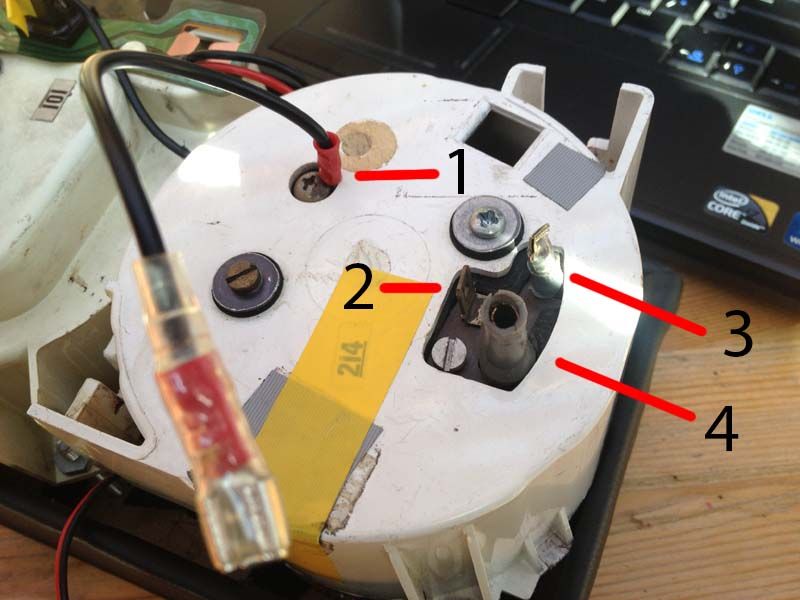
2. What is each connection of the back of my Rev counter. I'm pretty sure number 1 is earth. 


IMG_3464_1_zps1758b2c1.jpg


3. Where does the white lead go after the 3rd path of the alarm system? it leads back into the loom in the engine bay and i'm assuming it white for ignition?


Alarm_SystemDiagram_zps858a6449.jpg


4. Does it matter which is of the solenoid the positive and negative are on?


IMG_3463_1_zps152d0805.jpg


Thanks In advance guys. I really need some help on these. 


#2 Yoda

Yoda

    Camshaft & Stage Two Head

  • Traders
  • PipPipPipPipPipPipPipPip
  • 1,958 posts
  • Location: Dartford, Kent
  • Local Club: Medway mini club

Posted 26 August 2013 - 12:31 PM

Do not under any circumstances go any further!


you WILL have a fire and and possibly an exploding battery.


If you have a negative and a positive across that solenoid, as soon as you turn the key to the start position you will have a direct short through very high amperage cables if you have any power going to the ignition switch.


Please check how you have wired the solenoid against a correct wiring diagram. If you do not have a Haynes manual or similar, get one and read it!


If you do not know how things like solenoids work, you must get someone who understands car electrics to help you.


We can and will help, but you need to leave well alone until we can check your wiring.


You should have a short lead on the battery -ve going to a bolt in the boot floor and a long black cable going from the +ve battery terminal all the way under the car to the front that connects to the solenoid. the other terminal on the solenoid then connects via a shorter black cable to the starter motor. Check that this is so before doing anything else. but first please remove the negative terminal from the battery PLEASE!


#3 unique_name

unique_name

    Learner Driver

  • Noobies
  • PipPip
  • 17 posts
  • Location: Outback

Posted 27 August 2013 - 01:41 AM

Hi Yoda,


Thank you for the concern and this is partly why I have made this thread. I wanted to double check against the Haynes manual. Last thing I want is a fire.


Yes I understand what your have mentioned above. The battery is earth correctly in the boot and the cable leading to the solenoid is correct. I did take the car to an auto election who has check this and told me the 1st thing to do is  bolt the red + connections to the solenoid. Which you can see in the previous picture above.


The starter motor has a black 24 gauge cable leading to the solenoid.  ..


So I asked the original owner which diagram he used. He replied it was two years ago and I can't remember.. He then mentioned. He didn't really understood the Haynes manual that well and only used part of it.   I'm thinking. well isn't this great. So most of my time has been tracing wires and finding exactly where they go. Also the loom is brand new .


What should I check next? Thanks in advance.


#4 Barman

Barman

    One Carb Or Two?

  • Members
  • PipPipPipPipPipPipPip
  • 1,068 posts

Posted 27 August 2013 - 06:10 AM

Hi Yoda,


Thank you for the concern and this is partly why I have made this thread. I wanted to double check against the Haynes manual. Last thing I want is a fire.


Yes I understand what your have mentioned above. The battery is earth correctly in the boot and the cable leading to the solenoid is correct. I did take the car to an auto election who has check this and told me the 1st thing to do is  bolt the red + connections to the solenoid. Which you can see in the previous picture above.


The starter motor has a black 24 gauge cable leading to the solenoid.  ..


So I asked the original owner which diagram he used. He replied it was two years ago and I can't remember.. He then mentioned. He didn't really understood the Haynes manual that well and only used part of it.   I'm thinking. well isn't this great. So most of my time has been tracing wires and finding exactly where they go. Also the loom is brand new .


What should I check next? Thanks in advance.


Please clarify...


The black or the red cable in your picture goes to the battery positive in the boot...?


#5 Dan

Dan

    On Sabbatical

  • TMF+ Member
  • PipPipPipPipPipPipPipPipPipPipPip
  • 21,354 posts

Posted 27 August 2013 - 08:25 AM

  The crimp tag on the end of your red main battery cable is very poorly made, I imagine that it will show fairly high resistance and when it comes to delivering 150 amps will be a hot spot.  Someone has tried to get away without having to buy the proper, £75.00, heavy terminal crimp tool.  Doesn't work, you need a lot of force to close these crimps.  I am also concerned, as above, about why you are asking about a positive and negative at the solenoid.  The solenoid negative is it's mounting bracket, all the cables on it of whatever size are positive.


  Judging by the presence of a positive supply to the dizzy in your diagram I imagine you have electronic ignition.  This is an RVI tacho and simply put, will not work with your ignition if it is electronic.  In case that's an error on the diagram however:


  1 is tacho ground (actually I think they have used the wrong screw, it should be the small one by the bullets.  The one they have used is for something internal that hopefully hasn't been messed up by removing the screw), 4 is tacho power.  These do not have to go anywhere near the coil, they are just the power supply to the instrument. As standard tacho power would come from the accessory circuit (stereo, heater, wipers etc.), and the ground would be provided through the instrument PCB so this was originally a 2 clock car I would imagine.  Without swapping to the correct 3 clock PCB, which would provide that ground, you are going to have a hard time providing illumination to this gauge too.


  2 and 3 are the sensing circuit for the gauge.  The ignition supply cable (white) must run from the ignition switch to 2, then another cable from 3 to the coil provides coil power (white/green).  It's an RVI.  In order to provide immobilisation the white cable must also run through your alarm.  Without knowing more about the alarm it's hard to say for sure but judging by the diagram you have provided I would run it from the ignition switch, to 4 on the alarm, then from 3 on the alarm to 2 on the tacho, then from 3 on the tacho to + on the coil.  All other wires you have on the diagram are not needed.  There are too many white/red wires here and the extra white cable you can't trace must be the ignition supply I imagine.


  The diagram for this clock would be that of a 1975 1275GT.  Who knows what diagram the rest of the cars needs though!


#6 unique_name

unique_name

    Learner Driver

  • Noobies
  • PipPip
  • 17 posts
  • Location: Outback

Posted 27 August 2013 - 09:33 AM

Hi Barman,


I have updated my circuit diagram to answer your question. Yes you are all right. I was confused about the positive and negative on the solenoid. I didn't realise the black cable leading from the solenoid to the starter motor. Sorry for freaking you all out as it was a lazy mistake on my behalf. 


Alarm_SystemDiagram_zpse567a33f.jpg


Edited by unique_name, 27 August 2013 - 09:41 AM.


#7 Yoda

Yoda

    Camshaft & Stage Two Head

  • Traders
  • PipPipPipPipPipPipPipPip
  • 1,958 posts
  • Location: Dartford, Kent
  • Local Club: Medway mini club

Posted 27 August 2013 - 10:53 AM

No worries. 


Its just that we DO see some silly things done occasionally, so needed to make sure all was good on that side before worrying about the other issues.


Have a look at your diagram, if you take the alarm out of the equation, and connect white red from the ignition switch to the small terminal on the solenoid, you should get the engine to crank. If you then give the coil a 12v supply you should get the engine to fire. Then we can work out the wiring for the alarm at a later stage. ( make and model number of the alarm would be useful)


Follow the instructions you have already been given by others regarding the tacho/rev counter and you should then have all the components working as they should apart from the alarm/immobiliser which will at least get your car up and running.


Please pay attention to Dans comment regarding the battery feed connector, it really needs crimping or soldering properly before you draw too much current through it or you may end up with that fire i was concerned about to start with LOL


Edited by Yoda, 27 August 2013 - 10:55 AM.


#8 unique_name

unique_name

    Learner Driver

  • Noobies
  • PipPip
  • 17 posts
  • Location: Outback

Posted 27 August 2013 - 11:06 AM

  The crimp tag on the end of your red main battery cable is very poorly made, I imagine that it will show fairly high resistance and when it comes to delivering 150 amps will be a hot spot.  Someone has tried to get away without having to buy the proper, £75.00, heavy terminal crimp tool.  Doesn't work, you need a lot of force to close these crimps.  I am also concerned, as above, about why you are asking about a positive and negative at the solenoid.  The solenoid negative is it's mounting bracket, all the cables on it of whatever size are positive.


  Judging by the presence of a positive supply to the dizzy in your diagram I imagine you have electronic ignition.  This is an RVI tacho and simply put, will not work with your ignition if it is electronic.  In case that's an error on the diagram however:


  1 is tacho ground (actually I think they have used the wrong screw, it should be the small one by the bullets.  The one they have used is for something internal that hopefully hasn't been messed up by removing the screw), 4 is tacho power.  These do not have to go anywhere near the coil, they are just the power supply to the instrument. As standard tacho power would come from the accessory circuit (stereo, heater, wipers etc.), and the ground would be provided through the instrument PCB so this was originally a 2 clock car I would imagine.  Without swapping to the correct 3 clock PCB, which would provide that ground, you are going to have a hard time providing illumination to this gauge too.


  2 and 3 are the sensing circuit for the gauge.  The ignition supply cable (white) must run from the ignition switch to 2, then another cable from 3 to the coil provides coil power (white/green).  It's an RVI.  In order to provide immobilisation the white cable must also run through your alarm.  Without knowing more about the alarm it's hard to say for sure but judging by the diagram you have provided I would run it from the ignition switch, to 4 on the alarm, then from 3 on the alarm to 2 on the tacho, then from 3 on the tacho to + on the coil.  All other wires you have on the diagram are not needed.  There are too many white/red wires here and the extra white cable you can't trace must be the ignition supply I imagine.


  The diagram for this clock would be that of a 1975 1275GT.  Who knows what diagram the rest of the cars needs though!


Hi Dan,
 
Thank you for your reply. Yes I was confused regarding the postive and negative at the solenoid. I know rookie mistake :( Apart from that, Thank you for your lengthy reply. It's just what I needed.
 
I'm pretty sure it's a electronic ignition. How can I confirm this? I have also attached a picture of the engine bay.
 
If this is a RVI tacho.. How come it was workinig before? note: The old PCB had a bit of Frankenstein adaptation. Hence the reason why I replaced it.
 
I will need a bit of time to confirm all the tach connections and yes you are right. It use to be a 2 pod setup and I believe the previous owner just bought a 3 pod 1275gt setup.. Yes I agree with you regarding #1. I'm assuming it was ground due to the colour of the wiring. Is the only way to check this is buy opening the Tach?
I will connect #4 the tacho to the acceessory circuit. The original illumination to the tach was orginal done by soldeing wire's into the PCB. It's there a alternate to doing this?
 
Yes. The alarm system is a tad complicated. What would you need to know about the alarm system etc? I believe what you have posted is pretty much spot on and I will test it all out and post back my finding..
 
Engine Bay. Ignore white/blue wire as it's tempory

IMG_3496_zps79d933b9.jpg


OLD PCB

IMG_0610_zps829229fe.jpg


Other pics

Coil and Distributor.. 

http://i1272.photobu...zps018976a0.jpg

Close up Coil

http://i1272.photobu...zps3bdce0be.jpg

Distributor and Alternator

http://i1272.photobu...zps018976a0.jpg


#9 unique_name

unique_name

    Learner Driver

  • Noobies
  • PipPip
  • 17 posts
  • Location: Outback

Posted 27 August 2013 - 11:17 AM

No worries. 


Its just that we DO see some silly things done occasionally, so needed to make sure all was good on that side before worrying about the other issues.


Have a look at your diagram, if you take the alarm out of the equation, and connect white red from the ignition switch to the small terminal on the solenoid, you should get the engine to crank. If you then give the coil a 12v supply you should get the engine to fire. Then we can work out the wiring for the alarm at a later stage. ( make and model number of the alarm would be useful)


Follow the instructions you have already been given by others regarding the tacho/rev counter and you should then have all the components working as they should apart from the alarm/immobiliser which will at least get your car up and running.


Please pay attention to Dans comment regarding the battery feed connector, it really needs crimping or soldering properly before you draw too much current through it or you may end up with that fire i was concerned about to start with LOL


LoL I can imagine. I will pop into a auto electrician and get him to do a proper crimp/solder for me. I want to tick all my boxes as much as possible.


The auto electrician set up a temporary 12v feed to the coil so I could get the car cranking by connecting the solenoid terminals. I know it's not ideal.


I fill be following Dan's recommendations which will be very helpful.


Thanks for all the replies guys. It's just what I needed :D 


Link to Alarm Diagram

http://s3.amazonaws....11_VS1600XR.jpg


#10 Dan

Dan

    On Sabbatical

  • TMF+ Member
  • PipPipPipPipPipPipPipPipPipPipPip
  • 21,354 posts

Posted 27 August 2013 - 01:38 PM

Errm.  Yes, that's going to take some sorting out.  I really don't know what to say.  Is the previous owner on medication?  Errm.  Where are you located?


#11 unique_name

unique_name

    Learner Driver

  • Noobies
  • PipPip
  • 17 posts
  • Location: Outback

Posted 28 August 2013 - 02:38 AM

HAHAHA Yeah, That's what I was thinking.. A lot of the wire mess has come from me pulling the loom apart trying to trace where wires go.


I'm unfortunately in New Zealand. Your more than welcome to come over for a holiday ;)  I will be attend a mini club meet up tonight and I will have a good chat with the local master mechanic about the number of problems I'm having. 


I will keep the thread updated with everything.


#12 unique_name

unique_name

    Learner Driver

  • Noobies
  • PipPip
  • 17 posts
  • Location: Outback

Posted 12 November 2013 - 10:52 PM

Hi All,


Sorry for my delay in my reply. It has been a crazy at work and I have done a lot work on the car which isn't related to this topic.


So this is where i'm up to. With the mini master mechanic, We basically checked all of battery connections for the car. Some werid things where happening. Extra wire for no reason, Earth running from battery to the engine for no reason. So we have removed the extra wiring, Resolder all end correctly. Replaced dodgey connections on earth and postive connectors. Looks like this solved a couple of issues. Everything has been checked and fixed. Clearly the previous owner didn't know what he was doing.


So I have removed the alarm system from the car. As you all mentioning before this was causing more issues than what it is worth. I have have left the original wiring of the alarmfor the next owner.


I have made a little spade bridge between the iginition switch to coil “Where the alarm intersected the ingition to coil”and connected the the soilenoid wire to the ignition start. Boom she starts up like a dream.


So my next thing to do on my list is getting the rev counter working. I will be following Yoda recommendation of getting this to work. I will keep you posted on how it goes.


#13 Yoda

Yoda

    Camshaft & Stage Two Head

  • Traders
  • PipPipPipPipPipPipPipPip
  • 1,958 posts
  • Location: Dartford, Kent
  • Local Club: Medway mini club

Posted 13 November 2013 - 09:09 AM

Well done so far, but i think Dan gave you the advice for the rev counter, not me! so i cant take any credit for that!


Edited by Yoda, 13 November 2013 - 09:09 AM.


#14 unique_name

unique_name

    Learner Driver

  • Noobies
  • PipPip
  • 17 posts
  • Location: Outback

Posted 13 November 2013 - 09:21 AM

LoL. Yes you are correct. Sorry Dan, But Yoda I do give you credit as your have helped me in my journey.. lol


#15 Yoda

Yoda

    Camshaft & Stage Two Head

  • Traders
  • PipPipPipPipPipPipPipPip
  • 1,958 posts
  • Location: Dartford, Kent
  • Local Club: Medway mini club

Posted 13 November 2013 - 09:23 AM

And i will continue to do so where i can. Please send me your address so i can post the invoices LOL


1 user(s) are reading this topic

0 members, 1 guests, 0 anonymous users