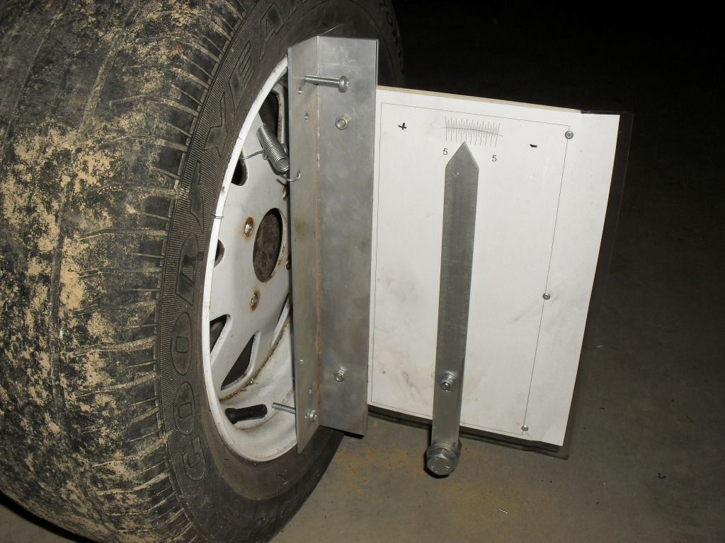
Is that just a bolt for a pivot and a big bolt for a weight Spider? I like it 
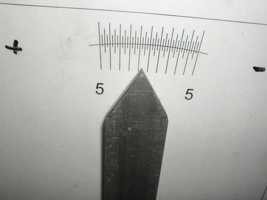
There is a Bolt in there for the pivot, however I filed it to a ^ for the pointer to move on - less friction and yeah, just an M16 Nut and Bolt of the bottom for a counter weight, though the hole is M20, so I can move it a tad to calibrate it. I really like it because I can see it (even without my glasses!) while I'm adjusting it, right there! I do have a 'Professional' Wheel Aligner 'Machine' but it's just sat in the corner for about 5 years now, too slow to use! I also made up a 'Lazer' aligner for doing the Toe Adjustment, which I can comfortable see from under the car while I'm adjusting. I'll try to remember to snap off a photo next time I use it.
I like the homemade idea. How did you print out the correct angle ?
By turntable are we just talking round plate with a bearing underneath it, so you can turn the wheels(side to side).I get the idea of flat level ground but won't the turntables will raise the front end up a little? or am I missing something ?
I made the back plate by first Drawing it on CAD, printing it and Laminating that, but no reason in the world why it couldn't be done the old fashioned way, pencil, protractor and a ruler. The one I've made here is marked down to 15" (or 1/4 of a degree).
The Turntables not only spin but also have a few inches of sideways travel. Mine are only about an inch high, for most stuff, I find that doesn't present a problem (there's more flex in the rubbers than any error that will make), however, anything with Poly Bushes or Rose Joints, I have some 10 x 1-1/2" Flat Timbers I place under the other set of wheels.


