Jump to content


Photo
- - - - -

Gauge Experts - The Insides Of A 12V Temperature Gauge Help

electrical

  • Please log in to reply
3 replies to this topic

#1 Timmehgane

Timmehgane

    Stage One Kit Fitted

  • Noobies
  • PipPipPip
  • 51 posts
  • Location: Stafford
  • Local Club: Torbay

Posted 28 March 2015 - 03:37 PM

Hey Y'all


My temperature gauge smoked out so I removed it from the car. Now I've finally got round to taking it apart and it looks pretty simple. But there's a couple of bits that either don't look right to me, or at least I'm struggling to comprehend how it works or if because its broken it looks like it does now


Please note, its not a named brand gauge, all that it is is on the back of the case "Japan", "12V", "I", "U" and "E".


In the 4 attached photos:


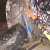
Looking at "main.jpg" there's a piece on the left that looks a bit orange and horrible, but nothing I would usually worry about in a gauge of this age

But on the right there's the wire wrapped around the piece of metal in a really rough way, and the piece coming out of the bundle looks to me where it probably burnt out because the white covering has gone and it looks like raw copper or something.


Looking at "touching.jpg" again there's the lever at the top right square that moves away from the piece its touching, whether it should be or not I don't know?


Looking at "focused.jpg" I'm pulling the lever away with the screwdriver so yee can grasp what I mean :)


The whole insides are impressively fragile, but I wasn't too sure what to expect so!


The needle attaches at the bottom in some fashion I can't quite work out but that's not my main issue


If anyone can help with what looks wrong / right /broken or anything, it would be much appreciated :D


I'm holding no hopes of getting it working again, but would be nice to know what happened or perhaps try and fix it :)


Thanks very much in advance :D

Attached Files


#2 dklawson

dklawson

    Moved Into The Garage

  • TMF+ Member
  • PipPipPipPipPipPipPipPipPipPipPip
  • 10,923 posts
  • Name: Doug
  • Location: Durham, NC - USA
  • Local Club: none

Posted 28 March 2015 - 07:24 PM

While those are great pictures I cannot see enough in them to tell you what has failed.  I can walk you through what is supposed to happen though.


The three pictures of the front of the gauge (the right-most 3) show both a bimetallic needle actuating strip on the left and a built-in voltage stabilizer on the right (the pieces with the contact points on the metal arms).  When you supply 12V to the gauge, current flows through the right-hand parts AND through the contact points on to the left-side parts.  The current leaving the points goes through the components on the left and off to the sending unit.  Current flowing through the right-hand parts heats the metal strip until it flexes from expansion and opens the points.  When those points open, current stops flowing to the left-side parts operating the needle.  The points open and close rapidly so that an "average" lower voltage (probably 10V or 5V) is supplied to the sending unit.


Again, I cannot see what failed but failure of either the right-side or left-side components can release white smoke.  In both cases, if the failure is the resistance wire, the gauge is not worth repairing at home.   It's not normal wire and it doesn't stand a good chance of surviving being soldered back together.


#3 Timmehgane

Timmehgane

    Stage One Kit Fitted

  • Noobies
  • PipPipPip
  • 51 posts
  • Location: Stafford
  • Local Club: Torbay

Posted 28 March 2015 - 08:01 PM

Ahhh right okay!


Thanks very much for the response!


By the sounds of it its not worth trying to repair then, ah well!
 

Do you happen to know what the wire is ? Curiosity now is all :)


#4 dklawson

dklawson

    Moved Into The Garage

  • TMF+ Member
  • PipPipPipPipPipPipPipPipPipPipPip
  • 10,923 posts
  • Name: Doug
  • Location: Durham, NC - USA
  • Local Club: none

Posted 29 March 2015 - 03:17 PM

The wires with the white, fuzzy insulation are probably nichrome like the wires used in electric toasters.  They have a specific amount of resistance per inch of length and are specifically made to provide controlled heat to the metal bits they are wrapped around.  Those metal "arms" are "bimetallic".  Rather than being one piece of a single alloy, one side is one metal, the other side a different metal.  The two metals have different coefficients of expansion.  When heated, one side grows longer than the other causing the metal arm to bow.


Also tagged with one or more of these keywords: electrical

1 user(s) are reading this topic

0 members, 1 guests, 0 anonymous users