Jump to content


Photo

Alarm System With Central Locking Installation Problem


  • Please log in to reply
2 replies to this topic

#1 giorgos1410

giorgos1410

    Learner Driver

  • Noobies
  • PipPip
  • 16 posts

Posted 13 July 2015 - 04:04 PM

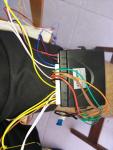
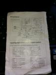
Hi guys, Yesterday i tried to install an alarm system with central locking and i faced some problems that i have no idea how to proceed. The main problem is that the alarm stayed armed! The wiring diagram is not saying everything (from what i understand). Please see attached files.

 post-49703-0-38971200-1436679770_thumb.j


I installed the actuators an the doors and i tried to work the system before the final installation. The problem is that the central locking is not working.

post-49703-0-59056400-1436679804_thumb.j


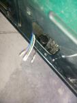
I can hear the alarm module to perform actions (blinking on unlock and lock) but actually the actuators are not working. From the main actuator there are 8 wires. The first 2 are the light brown and white, and the other 5 are together (those are the wires from the actuator and the red for the power wire).

post-49703-0-44946900-1436680264_thumb.j


Seems like those two left wires are signal wires? when i earth the brown one the actuators instantly perform lock and unlock action.


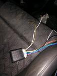
Now in attachment 4, is the alarm module. from left to right i have the LED Light harness and the Shock sensor harnes. Then i have one blue and one white wire. From the manual is saying that the blue is negative trigger and the white is KEY ON (ACC) POSSITION.


Then i have one orange (is for the foot brake switch) Not to use that

Green (trunk) not to use that

2 browns (for indicator lights)

Red (Live wire)

Pink for the siren

Black (earth)

Yellow (is going to the ignition) *** In the manual there is a relay where the yellow is end up - do i have to install a relay???


All those 10 wires are in the same harness


Next to that there is a harness with 6 wires

Yellow/black 

White/black

Orange/black

Yellow

White

Yellow


All those are for Central controllock arranging line.


Now does anyone have an idea how the wiring must be? 

Attached Thumbnails
  • post-49703-0-35547600-1436680417_thumb.j


#2 screech

screech

    Up Into Fourth

  • Members
  • PipPipPipPipPipPipPipPipPip
  • 3,136 posts
  • Location: West Sussex
  • Local Club: Bognor rock ya mini & WSMOC

Posted 13 July 2015 - 07:56 PM

As for the central locking. The red will need to be permanent live.
The brown and white are, as you say, trigger wires.
Pulse the brown to ground, will lock. Pulse the White will unlock.
The other 5 will be colour to colour on the actuators.

As for the alarm wiring, can you post a decent pic of the instructions? Can't zoom in on that one.

#3 giorgos1410

giorgos1410

    Learner Driver

  • Noobies
  • PipPip
  • 16 posts

Posted 15 July 2015 - 04:04 PM

Hi Screech, thanks for your answering. Please see the new photos of the wiring diagram. The first is for the alarm and the second for the actuators connection. As for the two wires you said, the brown and the white, depends if the mini's based on negative trigger or positive trigger isnt it? Do you know what it is? So i have to earth the brown and the white one has to be connected with the door switch? (dome light switch) Is that what you mean?


And if you know, can you please tell me about the yellows wires? where do they have to be connected? Do i need to use a relay or not?


Thanks a lot mate!! :)


Attached Files


1 user(s) are reading this topic

0 members, 1 guests, 0 anonymous users