Jump to content


Photo
- - - - -

Body Cracked Near Tower Bolt.. Help!


Best Answer sonikk4 , 24 December 2015 - 03:19 PM

Mmm a bit extreme to replace the complete crossmember or even that end.


First thing is to gain access to assess the damage. So remove the triangular gusset first. This is spot welded in place.


Now remove the tower bolt on this side only.


Strip off all of the paint in the affected area. Now you should be able to see the full extent of the damage. Now if ithe damage is not caused by rust then you have a couple of ways of repairing this. BUT before you remove anything else have a good look as far as possible on the underside of the crossmember. You will only see so much due to the subframe. If you find any further damage you will need to remove the subframe. 


1: Find the ends of the cracking and then use a 3/16th drill bit to drill a hole directly at the end of the crack / s. Now fully seam weld the crack / s and the hole / s drilled. Dress back the welds until flush. Prime and paint. refit the gusset and then tower bolt.


2. Now if it is rust damage you need to make a repair section. You will 1.2mm thick steel sheet for this. Fabricate your repair section first. Once done mark the are a affected and remove. Insert repair section and seam weld in place. Dress back the welds, prime and paint. attach the gusset then refit tower bolt.


Now as mentioned if you have a combination of solid mounts and rubber or poly then you need to either go fully solid or fully rubber. Bin the poly bushes.


Do thoroughly check the toeboard as this is normally the place that is affected by mixing solid and rubber.


To give an idea about rust causing this here is the damage i found behind the triangular gusset on Project erm. What looked like nothing turned into me doing this.

DSC02788.jpg


DSC02787.jpg

DSC02790.jpg

Go to the full post


  • Please log in to reply
9 replies to this topic

#1 daenesh

daenesh

    Speeding Along Now

  • Members
  • PipPipPipPipPip
  • 423 posts
  • Location: Malaysia
  • Local Club: Classic Car Owners Group

Posted 24 December 2015 - 10:51 AM

Hey guys, sorry for being dramatic.. hahaha well i have a 1978 clubby which has been prone to rust over the years. 

Lately i noticed the metal near the tower bolt starting to split. And I know it can be welded up but any idea what is causing this??

I'll let the pictures do the explaining. Any advise would be greatly appreciated. Thank you.


20151224_175718_zpsx4x2p421.jpg


20151224_175817_zpscpxmwfdp.jpg


#2 kezzkitkat

kezzkitkat

    One Carb Or Two?

  • Members
  • PipPipPipPipPipPipPip
  • 714 posts
  • Location: leicestershire

Posted 24 December 2015 - 11:16 AM

Two reason either the repair has not been done correctly so just keep splitting open or you have solid subframe mounts and the vibration is causing it to crack
But at a guess I would say it's the combination of the two

#3 minidaves

minidaves

    Up Into Fourth

  • Traders
  • PipPipPipPipPipPipPipPipPip
  • 4,933 posts
  • Location: kent
  • Local Club: mine

Posted 24 December 2015 - 11:43 AM

i suspect some other rust on the under side of the cross section, and poor repair strip it down and see what you have


dave


#4 tiger99

tiger99

    Crazy About Mini's

  • Members
  • PipPipPipPipPipPipPipPipPipPip
  • 8,584 posts
  • Location: Hemel Hempstead

Posted 24 December 2015 - 01:49 PM

Have you a combination of solid and rubber or poly mounts, or the pathetic all-poly mount kit that is readily available? That will ALWAYS result in structural cracking, for very obvious reasons, yet a depressingly large number of people insist on doing it. Not using front mounts at all, e.g. flip front with poorly designed brace bars, or none at all, will have the same result. The original design of Mini, before the soft mounts were introduced, was not prone to cracking, because Issigonis knew what he was doing. Some junior person seems to have designed the rubber mounts, and triggered lots of problems, including degraded handling.


The other places to check are around the toeboard mounts and the inner wings just ahead of or above the subframe towers. The latter is a right pig to fix properly if the cracks have opened out very far, as it means that the inner and outer wings will be somewhat out of shape. You need a lot of downward force at the front to close them up before welding. I know from experience, and in my case it was wrongly fitted washers on the front teardrop mounts, done by a bodyshop after a minor collision involving new wing, that caused the problem, but I have seen it on many other Minis. I did get the cracks closed up eventually (undid teardrop mounts and loosened all others, supported car under front edge of floor, and jumped up and down on front bumper), and welded a doubler plate over the area.


If none of those apply, you have high cycle fatigue cracking (unlikely, unless you have been stressing the car beyond its design limits, driving hard on really bad surfaces for example) or stress corrosion cracking (likely). In either case you must not just weld up the crack, but cut out the affected area and properly weld in fresh metal. Apply rust protection, and it will then last for very many years. If you just weld it up, you are only joining two bits of hopelessly fatigued metal together and it will fail again, near but probably not at the weld. The safety implications of it failing completely while on the move suggest that a proper, durable repair is essential.


Personally, I would take the easiest, but not cheapest or quickest, route (because I hate shaping bits of metal without a decent folder etc) and fit a new crossmember. Not a small job, but it leaves you with nice strong, new metal at both sides, in one of the most highly stressed parts of the shell. I would both plug and seam weld it, you can gain a little bit of stiffness and some extra crash protection that way. Do it right, and only do it once!


#5 sonikk4

sonikk4

    Twisted Paint Polisher!!!

  • Admin
  • PipPipPipPipPipPipPipPipPipPipPip
  • 16,053 posts
  • Name: Neil
  • Location: Oxfordshire

Posted 24 December 2015 - 03:19 PM   Best Answer

Mmm a bit extreme to replace the complete crossmember or even that end.


First thing is to gain access to assess the damage. So remove the triangular gusset first. This is spot welded in place.


Now remove the tower bolt on this side only.


Strip off all of the paint in the affected area. Now you should be able to see the full extent of the damage. Now if ithe damage is not caused by rust then you have a couple of ways of repairing this. BUT before you remove anything else have a good look as far as possible on the underside of the crossmember. You will only see so much due to the subframe. If you find any further damage you will need to remove the subframe. 


1: Find the ends of the cracking and then use a 3/16th drill bit to drill a hole directly at the end of the crack / s. Now fully seam weld the crack / s and the hole / s drilled. Dress back the welds until flush. Prime and paint. refit the gusset and then tower bolt.


2. Now if it is rust damage you need to make a repair section. You will 1.2mm thick steel sheet for this. Fabricate your repair section first. Once done mark the are a affected and remove. Insert repair section and seam weld in place. Dress back the welds, prime and paint. attach the gusset then refit tower bolt.


Now as mentioned if you have a combination of solid mounts and rubber or poly then you need to either go fully solid or fully rubber. Bin the poly bushes.


Do thoroughly check the toeboard as this is normally the place that is affected by mixing solid and rubber.


To give an idea about rust causing this here is the damage i found behind the triangular gusset on Project erm. What looked like nothing turned into me doing this.

DSC02788.jpg


DSC02787.jpg

DSC02790.jpg


#6 Blatherskite

Blatherskite

    Super Mini Mad

  • Members
  • PipPipPipPipPipPip
  • 501 posts
  • Location: Bærum
  • Local Club: Norsk Mini Cooper Club

Posted 24 December 2015 - 03:53 PM

Regarding drilling the crack tip, note that the tip will usually be very fine, and is often past where the hole gets drilled, as its so difficult to see without crack detection. You'll need a clean, shiny surface to have a chance by eye alone, and a torch to shine at various angles to get a good chance of getting the tip.

#7 midridge2

midridge2

    Camshaft & Stage Two Head

  • Members
  • PipPipPipPipPipPipPipPip
  • 1,794 posts
  • Location: north east england

Posted 24 December 2015 - 04:29 PM

I think its stress, caused by the coil spring suspension you have fitted. 


#8 sonikk4

sonikk4

    Twisted Paint Polisher!!!

  • Admin
  • PipPipPipPipPipPipPipPipPipPipPip
  • 16,053 posts
  • Name: Neil
  • Location: Oxfordshire

Posted 24 December 2015 - 05:43 PM

Regarding drilling the crack tip, note that the tip will usually be very fine, and is often past where the hole gets drilled, as its so difficult to see without crack detection. You'll need a clean, shiny surface to have a chance by eye alone, and a torch to shine at various angles to get a good chance of getting the tip.


If you have the right stuff to hand ie something like this http://www.ebay.co.u...MQAAOSwu4BV3tC4 then it takes the guesswork away from finding the end.


#9 daenesh

daenesh

    Speeding Along Now

  • Members
  • PipPipPipPipPip
  • 423 posts
  • Location: Malaysia
  • Local Club: Classic Car Owners Group

Posted 25 December 2015 - 12:06 AM

Great replies everyone.. Just to confirm I'm using all poly bushes from minispares except for the tower bush which is using a solid metal mount which I fabricated. Simply because the ones I got from minispares weren't sitting evenly.. They cost about £10 each to machine.. And the roads in Malaysia are horrendous with many uneven surfaces and bad deep potholes which I avoid but somehow hit 1 or 2.. I'm using rubber Dunlop cones but quite compressed with the hilos as I wanted a lowered look.. I even noticed a hairline Crack on the subframe just below that tower bolt affected area.. Which means substantial stress is being put on the driver side.. I'm only 90 kgs.. Hahaha

#10 tiger99

tiger99

    Crazy About Mini's

  • Members
  • PipPipPipPipPipPipPipPipPipPip
  • 8,584 posts
  • Location: Hemel Hempstead

Posted 26 December 2015 - 02:17 PM

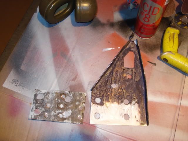
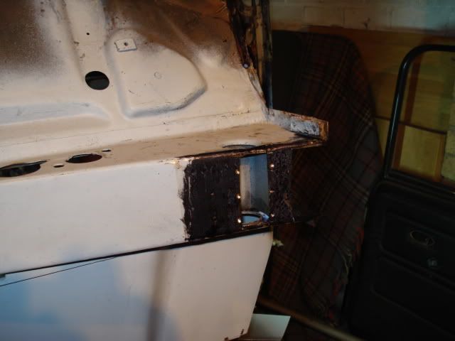
I thought so. The mixture of mounts is causing the cracking. It always does, even on average roads. You should preferably go to all solid, with reinforcing plates on the rear mounts. Otherwise, it is just going to happen again regardless of how well it is repaired. The poly mounts are completely useless anyway.


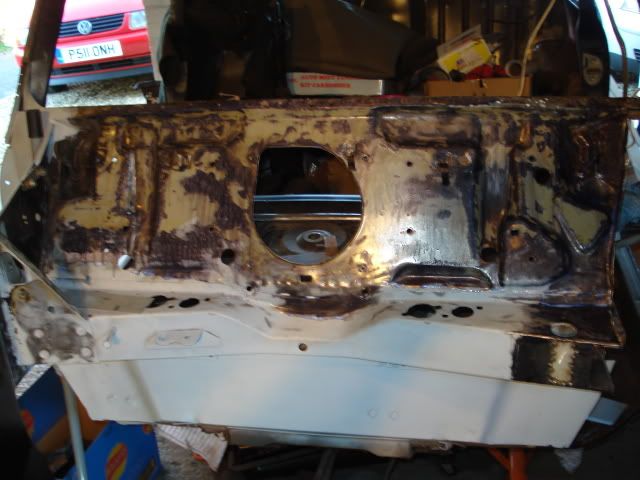
There is a fundamental issue with the main tower bolts, which may need careful attention. The shoulder of the bolt ideally needs to be up tight against the subframe, and the head of the bolt, plus any spacer that is needed, also needs to be in firm contact with the top surface of the crossmember. Any dimensional tolerances prevent that from happening, because one or the other will make contact first. I would be inclined to make the top spacer just a couple of thou too thick, and allow a very small amount of crush on the crossmember when the bolt is torqued down tight. It might not matter in most cases, but if the roads are as you say, every little bit helps, and you really should try to aim for the bolt being bottomed and getting good clamping load. If the bolt shoulder is not bottomed tightly against the subframe, you may get fretting, and failure of the thread.


One other method is to put a stack of thick Belleville washers, all facing the same way, under the bolt head, and ensure that when the bolt bottoms against the subframe, the stack is compressed almost flat. If the face the same way, the spring rates are additive, and you get a good clamping load. Using them as springs, they normally face alternate directions, which you don't want here. You need a clamping load, which can be calculated from the spring compression, of maybe 1 to 2 tonnes each side, to ensure that there will be no movement, and therefore fretting, under worst case conditions. The internal spacer in the crossmember needs to be in good condition to take the load.


http://www.schnorr.c...sc-springs.html


Some people have achieved the same result by fitting the top half of a poly tower mount, and a solid spacer between subframe and bulkhead, with the poly providing the amount of crush needed to take up the tolerances. That is very hit and miss, and may work ok sometimes, but you can't tell how much compressive load the bolt is applying to the joint faces, because the crush properties of the poly bush are completely uncalibrated.


Another possibility is to machine the hexagon head of the bolt off in a lathe. (I don't mean cut it off, just reduce it to the same diameter as the bolt.) Thread the end. Tighten the modified bolt into the subframe, put your top spacer on, followed by a lockwasher and nut, and torque up. All tolerances taken up at both ends. Should be good.


Actually the best way of getting a very firm and fatigue-free structure is to put the car back to the configuration which Issigonis designed, with twin tower bolts or studs, solid fromt mounts, and the rear mounts attached at the stiffest point, the junction of lower bulkhead and floor, but that is a lot of work. Nevertheless, earlier cars with solid mounted subframes are more robust, but may be more dangerous in frontal impacts.


Another thing to think about is that on the old two bolt subframes, the spacer between subframe and bulkhead was rather large, as it spanned both bolts, which if I recall correctly were 2.5 inches apart, and formed a good load spreader. Nothing to stop you fitting larger spacers, except that you can't just turn them up on a lathe, as they are not circular, and you would waste a lot of material. The original lower rubber would give a rough indication of the size to aim for, as it was much the same size as the old metal spacer.


I am sure that you will be glad to know that your HiLos have nothing to do with the problem. They do put the bottom of the car at risk if you hit a very bad pothole, just because it is lower, but in general will not increase the peak spring (rubber cone) load significantly. Some HiLos have a shaped platform to effectively increase, for initial deflection only, the spring rate, but under severe bump conditions that becomes irrelevant.


1 user(s) are reading this topic

0 members, 1 guests, 0 anonymous users