Jump to content


Photo

Spi Relay Pack Help


  • Please log in to reply
6 replies to this topic

#1 minisilverbullet

minisilverbullet

    Up Into Fourth

  • TMF+ Member
  • PipPipPipPipPipPipPipPipPip
  • 3,799 posts
  • Name: Craig
  • Location: Sweden

Posted 06 June 2016 - 05:05 PM

I am in the process of converting my SPi to a SC Twin K engine. 


I will use the SC ECU, I have seen other builds from SPi/MPI bases and these retain the relay pack.


So while this isnt strictly an SPI question, i hope someone can help. 


I have removed all the SPi engine management loom/ECU and sensors. 


I am left with the main relay pack and all the things which directly attach to it. 


some questions:


QUESTION/TOPIC 1


Is this the O2 sensor relay?

81699ADF-F082-46F7-90CA-C4FD9120EA40_zps


it has blue/red wire which ran to the sensor 

black/green wire i understand to the ECU

brown/pink from the main switched live (large connector on relay pack) 

brown from the starter.  


Now my new ECU will connect directly the 02 sensor. I guess the O2 relay is now redundant. But what about the brown and brown/pink wires, is it as easy as removing these completely? 


QUESTION / TOPIC 2


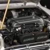
This is a picture of the relay pack. 


I have managed to identify almost all wires using various diagrams (and very helpful picture from Flyingscot). The top left the colour os brown/pink, which differs from Flyingscots picture, but can I assume it is also a "main switched live"?


Also in my picture you will see a brown/blue wire which ran to the manifold heater. Can I just completely remove this terminal, without disturbing anything else? 


B2B747F5-22E4-4290-9170-2856587E5CEE_zps


Screen%20shot%202016-06-06%20at%207.13.4


QUESTION / TOPIC 3


This  query refers to the two "redundant wires" connected to the o2 sensor, namely:


- brown/pink from the main switched live (large connector on relay pack) 

- brown from the starter.  


the New ECU requires a permanent live and switched with ign live. I guess these two o2 wires can be used? 


#2 tmsmini

tmsmini

    One Carb Or Two?

  • Members
  • PipPipPipPipPipPipPip
  • 728 posts
  • Local Club: MOASF

Posted 06 June 2016 - 06:58 PM

Are you using an SC provided wiring loom?

What provisions does it have for the lambda sensor?


I would have to review an SPi diagram, but the ecu may connect directly to the signal wire from the lambda sensor, but the relay is for the lambda sensor heater.

Are you using a wide band lambda sensor provided by SC?


Wiring diagrams:


Terry


Edited by tmsmini, 06 June 2016 - 07:26 PM.


#3 minisilverbullet

minisilverbullet

    Up Into Fourth

  • TMF+ Member
  • PipPipPipPipPipPipPipPipPip
  • 3,799 posts
  • Name: Craig
  • Location: Sweden

Posted 06 June 2016 - 07:38 PM

Cheers Terry, 


I have those wiring diagrams, unfortunately  they are for Mpis and japanese SPis. The Japanese one is close but not 100%, that is what i have been using.


Yip, I am using the SC loom, It has all the provisions for the Lambda sensor. 


it looks like there is a lot from these really packs which is redundant. 


#4 minisilverbullet

minisilverbullet

    Up Into Fourth

  • TMF+ Member
  • PipPipPipPipPipPipPipPipPip
  • 3,799 posts
  • Name: Craig
  • Location: Sweden

Posted 07 June 2016 - 11:06 AM

Seems like i had an SC loom for an earlier car. 


SC will send a new loom out today.


I guess that will help me a lot. 


#5 FlyingScot

FlyingScot

    Up Into Fourth

  • TMF Team
  • PipPipPipPipPipPipPipPipPip
  • 2,664 posts
  • Location: Inverclyde Scotland
  • Local Club: Mini Cooper Register

Posted 07 June 2016 - 04:21 PM

Just to close your questions Craig, sorry was under a car the last days...

Answer 1 yes that's the lambda relay, if not needed cut back and cap with heat shrink.

Answer 2 yes switched live, they changed colours on some years/models. Manifold PTC can be cut back and capped.

Answer 3 yes you could use these if the cable is in a suitable place.

You will end up using the only the main relay and starter I'm guessing, not sure about the fuel pump circuit with your new set up presumably you could splice into the existing signal side (small plug) of the MFU ?

Or perhaps the correct loom is plug and play?

FS

#6 tmsmini

tmsmini

    One Carb Or Two?

  • Members
  • PipPipPipPipPipPipPip
  • 728 posts
  • Local Club: MOASF

Posted 07 June 2016 - 04:50 PM

When we adapted our MK I to use an MPi engine, we had to decide to use either the SC provided MPi loom or the SC provided standard Mini loom and make changes as needed.

We went for the MPi loom which meant we kept the multi function unit. I am not sure that was the best choice. I have a number of connectors not in use.


I would think the SC provided loom for the K head would have provisions for all the relays and power feeds needed, so that you could do away with the MFU.

But if they have a K head loom for the MPi, it would make sense to keep it.


Does the British Heritage manual CD have the correct diagram for the early SPi? My version no longer works as it only runs on Windows XP.


Edited by tmsmini, 07 June 2016 - 05:04 PM.


#7 FlyingScot

FlyingScot

    Up Into Fourth

  • TMF Team
  • PipPipPipPipPipPipPipPipPip
  • 2,664 posts
  • Location: Inverclyde Scotland
  • Local Club: Mini Cooper Register

Posted 07 June 2016 - 06:51 PM

http://www.dries.net...ual - 92-96.pdf

FS

Edited by FlyingScot, 07 June 2016 - 06:52 PM.


1 user(s) are reading this topic

0 members, 1 guests, 0 anonymous users