Jump to content


Photo

Flywheel Clutch Balancing Information Help Please


  • Please log in to reply
18 replies to this topic

#1 ryomini

ryomini

    Super Mini Mad

  • Members
  • PipPipPipPipPipPip
  • 583 posts
  • Location: Hiroshima

Posted 08 June 2016 - 01:39 PM

Again hello to all you good mini people and Spi lovers


just nudging along with my build,

getting to putting the box back on

and then the flywheel and clutch


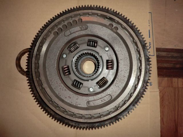
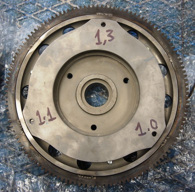
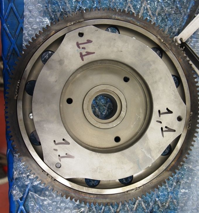
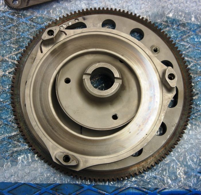
As you can see from the pictures the original Spi flywheel is balanced with some serious little holes drilled out in strategic places

CIMG3376_zpszgjn35hh.jpg

CIMG3377_zpsltw38f27.jpg


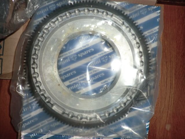
As I understand I need to mount the new Minispares steel flywheel to the other clutch parts and get it dynamically balanced.

As my local machinist is not likely to be familiar with the Mini clutch where exactly is / are the best spots to drill (do people add weight, I don't think they do, do they)


I want to be able to give the machinist the maximum amount of info possible, which can be a bit tricky as we often don't speak the same language

if anyone has pictures or drawings of a balanced billet steel Spi flywheel I would be very very grateful


as usual thanks so much to you all for your enthusiasm, knowledge and for sharing

let's hope I can get this engine together


#2 Fast Ivan

Fast Ivan

    Up Into Fourth

  • Members
  • PipPipPipPipPipPipPipPipPip
  • 2,909 posts
  • Location: Earth

Posted 08 June 2016 - 04:42 PM

unfortunately you cant tell where you need to drill the holes until you check the balance, your original flywheel would have been heavy on the side with the drill holes

also, I don't think its necessary to dynamically balance the whole assembly unless your revving the nuts off it, which considering you have an SPI and therefore a fairly mild cam, you wont be

so realistically you probably only need the flywheel assembly done


I would advise sending AC Dodd a message; he will be better placed to give you advice and he may part with some valuable information that you can pass on to your machinist


#3 Carlos W

Carlos W

    Mine is purple, but I have been told that's normal

  • TMF+ Member
  • PipPipPipPipPipPipPipPipPipPipPip
  • 10,110 posts
  • Location: Sittingbourne, Kent

Posted 08 June 2016 - 05:05 PM

Find a bearing that fits in the hole, put it on a shaft and spin it slowly, mark the lowest point, if this is the same place every time this area is heavy


#4 brivinci

brivinci

    One Carb Or Two?

  • Members
  • PipPipPipPipPipPipPip
  • 1,095 posts
  • Location: New Jersey

Posted 08 June 2016 - 07:20 PM

That is Mini Spares "lightened" flywheel, correct? It should be balanced already on its own. Are you looking to assemble it fully and then balance it? With the clutch disk and pressure plate in place?


#5 ryomini

ryomini

    Super Mini Mad

  • Members
  • PipPipPipPipPipPip
  • 583 posts
  • Location: Hiroshima

Posted 09 June 2016 - 12:37 AM

Thanks for your feedback

@Ivan exactly but there are some areas where it is not a good idea to drill a hole, and other areas where it is better Contacting AC is an ace idea, if he is happy to help out that would be amazing

@carlos that kind of home balancing is better than nothing but this thing is going to be spinning at 6000rpm so you don't really want it to be wobbling around - yes I will balance the assembly but not with the crank it's just too much for me to do - so just the plate and clutch parts


@brvinci - no actually mini spares recommend that you balance the unit assembled to clutch parts.  How well it is balanced out of the box I don't know as it's not easy to balance an item with such a big hole in it !


#6 nicklouse

nicklouse

    Moved Into The Garage

  • TMF+ Member
  • PipPipPipPipPipPipPipPipPipPipPip
  • 17,899 posts
  • Location: Not Yorkshire
  • Local Club: Anonyme Miniholiker

Posted 09 June 2016 - 07:15 AM

just to state the obvious you do not include the clutch plate/friction plate.


just everything else.


#7 brivinci

brivinci

    One Carb Or Two?

  • Members
  • PipPipPipPipPipPipPip
  • 1,095 posts
  • Location: New Jersey

Posted 09 June 2016 - 02:02 PM

Sorry, that is what I was getting at. The plate/friction plate is not included. I was wondering if MS told him it was. Then you know you are getting the wrong info:-)


#8 Ethel

Ethel

    ..is NOT a girl!

  • TMF Team
  • PipPipPipPipPipPipPipPipPipPipPip
  • 25,379 posts
  • Local Club: none

Posted 10 June 2016 - 08:07 AM

No point in balancing bits that spin independently every time you press the pedal. It's the heavier back plate that makes it always a good idea with Vertos. Even if every bit has perfect balance itself there's no guarantee they will bolt together perfectly concentric.


#9 MontpellierVanMan

MontpellierVanMan

    Mini Mad

  • Noobies
  • PipPipPipPip
  • 102 posts
  • Location: Montpellier

Posted 10 June 2016 - 05:30 PM

Interested in this as was about to get my crank / flywheel balanced, and was puzzled by the idea that you would balance the clutch back-plate as well as the flywheel, when - as has been pointed out - it doesn't necessarily spin 100% concentrically with the flywheel.


I have a lightened steel flywheel Pre-Verto fitted to my 1380 and the back-plate is ostensibly machined on every face and would logically be perfectly symmetrical and balanced about its centre ; however there is obviously some limited slop on the three pillars that locate it in the flywheel, and unless one were to centre it very carefully (is that even possible ?) by adjusting the position of all the flat straps, it is never going to run true - even if its position ought to remain constant once the 6 strap-bolts are hard up ?


The pressure plate however is reliably located on its 3 bolts and can go back in the same place each time, so presumably this is included during the balancing simulation ?


Anyone with hands-on and informed input about this ? I'll be on the spot when I get mine done, would pictures be worthwhile ?


#10 ryomini

ryomini

    Super Mini Mad

  • Members
  • PipPipPipPipPipPip
  • 583 posts
  • Location: Hiroshima

Posted 10 June 2016 - 11:20 PM

hummm

again thanks for more feedback

I see I have not fully understood the criteria

yes I was under the impression that the clutch assembly needed to be balanced as a unit

some people even go as far as balancing the assembly attached to the crank


If I was to balance the flywheel alone I would need a jig as the aperture is the size of a black hole !

with the heavy pressure plate would be easier that is for sure


so as Nicklouse says (and I know that you have a lot of experience in Mini building) I am not sure I understand why you wouldn't include the friction pad as well, it's got to spin in there too (obviously it's going to wear though)


I am wondering then should I balance the flywheel bolted to the heavy pressure plate but NOT including the lighter clutch pad - is that the BEST or should I just balance the flywheel alone set up on a special jig ????


I must admit it is still not totally clear to me. 


(and as for getting the dowels in, I left the flywheel out in the sun and put the dowels in the freezer, lubed up the holes but still needed a pretty hefty hammer to drive those dowels home)


#11 Carlos W

Carlos W

    Mine is purple, but I have been told that's normal

  • TMF+ Member
  • PipPipPipPipPipPipPipPipPipPipPip
  • 10,110 posts
  • Location: Sittingbourne, Kent

Posted 11 June 2016 - 08:06 AM

When the clutch is pressed it doesn't spin at the same rate as the engine, therefore its position changes relative to the rest of the assembly.


You could balance it separately


#12 Ethel

Ethel

    ..is NOT a girl!

  • TMF Team
  • PipPipPipPipPipPipPipPipPipPipPip
  • 25,379 posts
  • Local Club: none

Posted 11 June 2016 - 10:19 AM

I would guess anyone who's set up to dynamically balance Mini flywheels has a crank tail shaped mandrel (e.g. - a crank) for their balancing machine.Another reason to do Vertos as an assembly.


#13 ACDodd

ACDodd

    Up Into Fourth

  • Mini Docs
  • PipPipPipPipPipPipPipPipPip
  • 2,646 posts

Posted 11 June 2016 - 11:15 AM

This what I use.

Ac

Attached Files


#14 ryomini

ryomini

    Super Mini Mad

  • Members
  • PipPipPipPipPipPip
  • 583 posts
  • Location: Hiroshima

Posted 27 June 2016 - 04:18 AM

AC

that mandrel is a very RARE item !


#15 MontpellierVanMan

MontpellierVanMan

    Mini Mad

  • Noobies
  • PipPipPipPip
  • 102 posts
  • Location: Montpellier

Posted 27 June 2016 - 07:58 AM

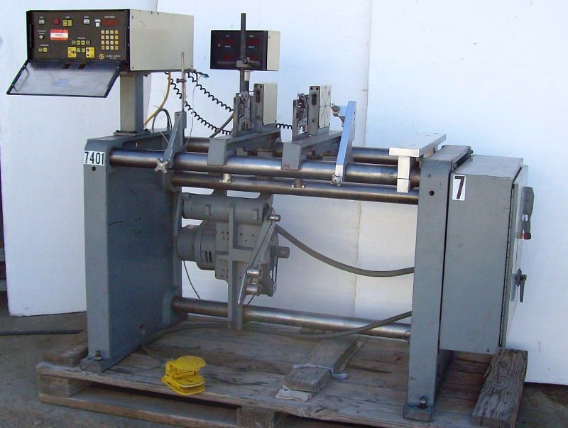
Getting the crank balanced tomorrow on a dynamic soft-bearing something like this,


Balancer_zpsxqgw1n66.jpg


- apparently done at 250 then 500 then 1000 rpm, will post pictures.


DSC01177_zpsxcnmnypd.jpg


But still unhappy about a glaring inconsistency with the way the reasoning goes over the whole issue regarding the clutch back-plate.


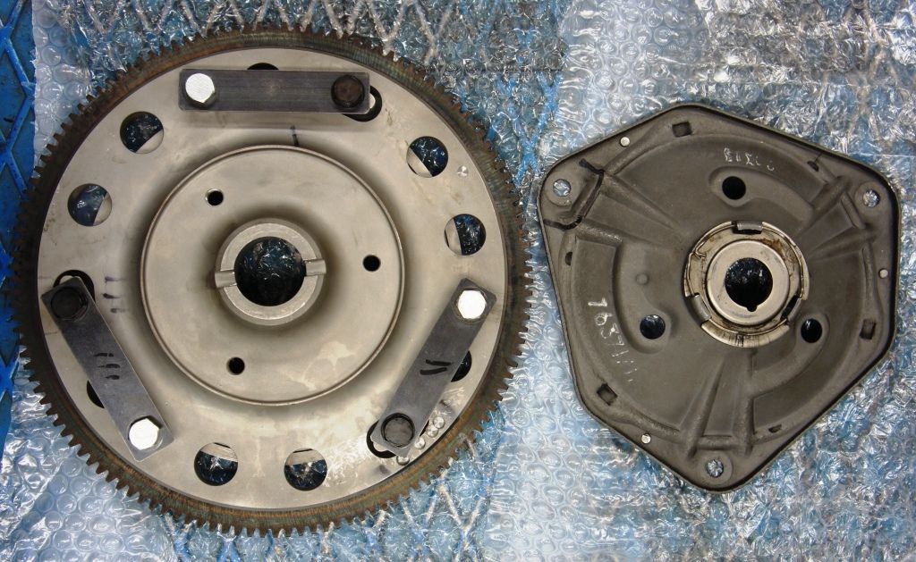
Imbalance is expressed in gramme.mm and I have heard a maximum of 100 g.mm quoted as a goal to aim for. The small holes visible in the flywheel can attest to previous nit-picking balancing.


DSC01175_zpsfhcmybrd.jpg


Yet according to the way you might subsequently "centre" or fit the clutch back-plate (which, being machined on all faces in this instance, is probably pretty inherently balanced) you can easily change the centre by 0.2mm - and I would guess on the original set-up by a whole lot more ? The scribbles are the edge-gaps measured with feeler-guages.


DSC01176_zpszgcjof1p.jpg


Now even a lightened back-plate like this weighs 1.75 kg .............. so you can throw the whole thing out by 350 g.mm just by fitting the clutch back-plate.


DSC01178_zpsno1tftvf.jpg


I am tempted to build the whole assembly including the clutch friction plate, which is a) light and b) symmetrical and c) of a relatively small diameter, with the back-plate centred as shown, and do the final crank + flywheel + clutch balancing with everything present.


Any informed comments on that ?


1 user(s) are reading this topic

0 members, 1 guests, 0 anonymous users