Jump to content


Photo
- - - - -

Front Subframe Re-Assembly Process


  • Please log in to reply
14 replies to this topic

#1 jabos7

jabos7

    Stage One Kit Fitted

  • Noobies
  • PipPipPip
  • 89 posts
  • Location: Hagerstown, MD

Posted 04 November 2016 - 12:55 AM

After a complete teardown/strip of my '73 MkIII, (with dry suspension) I'm finally starting the climb back up out

of the valley of "Why did I do this?"  I removed the engine first, then dropped front and rear subframes.   While working

on the body (a lot) I've been re-furbing both subs.


 -Which brings me to my question, of how far can I take the front subframe re-assembly/build-up without kicking myself later for going too far and un-doing a bunch of new work???

The rear sub was very straightforward and sits ready-to-mount.   But the front is getting changed from drums to discs,

and I can't tell where I should stop to prevent having engine-install problems later. 


I've installed upper and lower arms, and new tie rods to frame and lower arms.  My hubs have races installed, along with

ball joints.  Will I be safe continuing with bearings/CV axles/ then driveshafts?  Maybe calipers and brake lines as well,

knowing that I'll have to do the most serious torquing after it all sits on the ground?

I have the rubber couplings and U-bolts at the tranny/diff.    -What would be the point at which, as the engine goes in, the

last of the driveline joins up?   The choices of CV-to-driveshaft, or drive shaft-to-coupling-yoke (where the

gaiters are involved), or all the way to the rubber coupling yokes, lacking only the U-bolt final attachment?


My goal is to get the body painted before winter sets in, re-attach the subs and get her on wheels, then enjoy an engine

teardown during the dark months ahead.


Your recommendations would be greatly appreciated!  -J


#2 nicklouse

nicklouse

    Moved Into The Garage

  • Members
  • PipPipPipPipPipPipPipPipPipPipPip
  • 18,701 posts
  • Location: Not Yorkshire
  • Local Club: Anonyme Miniholiker

Posted 04 November 2016 - 01:03 AM

Fit everything.

Leave the yokes of the drive shafts. BUT they will need to go on before the engine is fully installed.

What you can do is knock the cups plastic Out of the closed end so that they can be slide further up the drive shafts allowing more space for the yokes on the diff to pass.

The other option is to not snug up the top ball joint bolt so you can easily pop the taper out of the top arm and swing the drive shaft from the diff.

#3 jabos7

jabos7

    Stage One Kit Fitted

  • Noobies
  • PipPipPip
  • 89 posts
  • Location: Hagerstown, MD

Posted 04 November 2016 - 03:25 PM

Okay, I understand your options.  -safe all the way to the yokes, including driveshaft gaiters.  Are the plastic cups very forgiving of

removal/refit?  Or should I buy a pair to have on hand?


Also--is it okay to tighten everything but the end axle nuts while it sits on the bench, or should that wait until mounting with

weight on the wheels when I do the heavy axle nut torque?    

Thanks --J


#4 tiger99

tiger99

    Crazy About Mini's

  • Members
  • PipPipPipPipPipPipPipPipPipPip
  • 8,584 posts
  • Location: Hemel Hempstead

Posted 04 November 2016 - 08:35 PM

The only parts that you can't tighten on the bench are the drive shaft U bolts (obviously!) and the rubber bushed joints ie tiebar and lower arm, which must be tightened at the vehicle's ride height, whatever you have set that to. Anything else, such as hub nuts, depends only on whether you can restrain the item in question while applying lots of torque. That depends on what you have at your disposal and how confident you are about the procedure. For instance, a tool consisting of a flat plate that bolts over the wheel studs and is held in an extremely well anchored vice might be a useful asset. Otherwise I suggest leaving those that will not be torqued up immediately very visibly loose and maybe with a red label so they don't get forgotten later.

I assume that this is an early Mini with rubber drive shaft couplings. Originality may be important to you, especially on a valuable vehicle. Otherwise I would suggest getting rid of those...

Many years ago there was a Quinton Hazel conversion kit with ordinary Hooke Joint UJs adapted by nylon mouldings to fit the yokes for the rubber joints. If you ever find one of these kits, I suggest acquiring it as it was a legitimate period modification, albeit causing some harshness in the drive train. It is as important a part of the Mini history as anything else.

#5 jabos7

jabos7

    Stage One Kit Fitted

  • Noobies
  • PipPipPip
  • 89 posts
  • Location: Hagerstown, MD

Posted 09 March 2017 - 01:21 AM

Hoping to get some plumbing advice as the process continues -


I've re-fitted the restored front subframe and started working underneath to re-install my

Brake line

Battery cable

Fuel Line


Can someone give me routing paths for these at the front subframe?   I have my pictures from the tear-down, but have found

too many questionable repairs on the car to trust their placement as I found them.


Previously, the brake line and fuel hose from its line came up between the steering rack and the floor/firewall on their respective

sides. --I'm worried about the steering rack bellows working around them

And the Battery cable came up under all of this and into the subframe/engine area, I believe with some locating clips to get it routed to the

solenoid/starter area.


Any guidance or pics would be appreciated to do this properly.


#6 Spider

Spider

    Moved Into The Garage

  • Admin
  • PipPipPipPipPipPipPipPipPipPipPip
  • 15,154 posts
  • Location: NSW
  • Local Club: South Australian Moke Club

Posted 09 March 2017 - 01:59 AM

I build up the subframe, with the arms, cones etc as one sub-assembly, the hubs, with the drive shafts as another, callipers (with hoses fitted) as yet another, steering rack another, and the 'power-unit' as a complete sub-assembly.


While 'on the bench', I make up the brake pipe(s), to enable me to do this, I'll temporarily fit the brake hoses.


Then at fit up time, I work in the following order;-


Steering rack

Subframe

Hubs

Callipers

Brake line


At this point, if the Rear Subframe is in, I can complete the Brake Pipes and Bleed the Brakes (if there's no Servo) and check for leaks. Once I'm happy with all that, I fit the Power Unit.


#7 GraemeC

GraemeC

    Crazy About Mini's

  • TMF+ Member
  • PipPipPipPipPipPipPipPipPipPip
  • 7,440 posts
  • Location: Carnforth

Posted 09 March 2017 - 09:09 AM

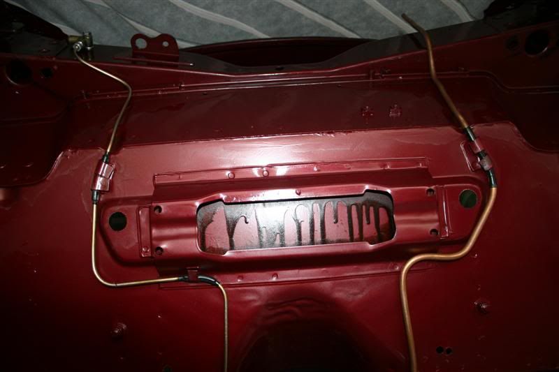
Battery cable goes in after the subframe and is usually secured to the RHS subframe leg with a P-clip


Front/rear brake pipe and the fuel pipe should be fitted before the steering rack, and hence before the subframe.

IMG_4201Medium.jpg


#8 jabos7

jabos7

    Stage One Kit Fitted

  • Noobies
  • PipPipPip
  • 89 posts
  • Location: Hagerstown, MD

Posted 09 March 2017 - 07:14 PM

Beautiful shot, great explanation!   Nice work in the pic--Is that heatshrink on the lines or something else

for protection?


Thanks for the definitive reply!  -J


#9 tiger99

tiger99

    Crazy About Mini's

  • Members
  • PipPipPipPipPipPipPipPipPipPip
  • 8,584 posts
  • Location: Hemel Hempstead

Posted 09 March 2017 - 07:18 PM

The battery cable has two P clips, one inside the lower flange of the side member, fixed by self tapper (should be hole in bottom) and the other has a long white plastic spacer and a bolt which is about 3/16" diameter. It goes into a hole in the rear subframe leg. with from memory a nut and lockwasher on top,  to keep the cable well away from the exhaust. It helps the cable to bridge the gap between the floor and the subframe flange and prevents it moving sideways. It is actually rather important, on models where it is needed! I can't say that it was fitted to all models, but definitely on many 998s with either rubber or solid subframe mounts. It was likely omitted on later models as the cable was routed differently.


Funnily enough it is missing from the Somerford web site, which has the clips and screws,  here:


http://www.somerford...page=page&id=70


#10 GraemeC

GraemeC

    Crazy About Mini's

  • TMF+ Member
  • PipPipPipPipPipPipPipPipPipPip
  • 7,440 posts
  • Location: Carnforth

Posted 10 March 2017 - 08:06 AM

Beautiful shot, great explanation!   Nice work in the pic--Is that heatshrink on the lines or something else

for protection?


Windscreen washer tube held in place with heatshrink


#11 jabos7

jabos7

    Stage One Kit Fitted

  • Noobies
  • PipPipPip
  • 89 posts
  • Location: Hagerstown, MD

Posted 25 April 2017 - 12:50 AM

A follow-up Front Sub question, added to my own build-up questions above:


As I'm rolling around in and under my MK3 getting everything re-wired and re-plumbed, I found what looks like attachment points that I cannot

account for from the dis-assembly:


At the base of each inner fender/facing the engine, there are 2 holes that line up perfectly with the Front Subframe sides.  Should there be

some sort of clip/hardware there to attach the inner fenders to the sub?   Are these for another purpose, such as securing a fender-liner?


Any info would be greatly appreciated


#12 tiger99

tiger99

    Crazy About Mini's

  • Members
  • PipPipPipPipPipPipPipPipPipPip
  • 8,584 posts
  • Location: Hemel Hempstead

Posted 26 April 2017 - 11:49 AM

The subframe is only attached at 6 points, the two front corners, to the front panel, the two towers to the bulkhead and the two rear legs at the toeboard.

Any side fixings are incorrect and should not be bolted. There should be a small clearance between subframe and inner wing along each side and sometimes there may be a small rubber grommet-like buffer to prevent rattling.

#13 jabos7

jabos7

    Stage One Kit Fitted

  • Noobies
  • PipPipPip
  • 89 posts
  • Location: Hagerstown, MD

Posted 26 April 2017 - 02:51 PM

Makes sense-  Could these two oblong holes at the base of each inner well be the placement for these grommets?


Maybe I can procure a rubber plug/bumper that would fit these spaces and either help stand the inner well off of the

the subframe, or at least be close enough to take the small shock away if anything flexes?


#14 tiger99

tiger99

    Crazy About Mini's

  • Members
  • PipPipPipPipPipPipPipPipPipPip
  • 8,584 posts
  • Location: Hemel Hempstead

Posted 27 April 2017 - 08:46 PM

The rubber buffers I am thinking of were small and circular and at the lower corner of the inner wing just ahead of the subframe tower, but I can't find any reference to them anywhere. Maybe at least one of my Minis had been modified because it rattled?


Just make sure that there is some clearance, and bend (pull, no levering needed) the inner wing lower edges outwards by hand if necessary. If you are using solid mounts (highly recommended) there is no movement at the front corners and only the lower corner has any tendency to vibrate.


My third Mini initially had rubber mounts (until the toeboard mounts broke twice in 20k miles!) but the shell had been badly thrown together at the factory, so the subframe did not fit properly between the inner wings at the front. I assume that the error was that the two mounting ears for the front panel had been wrongly shaped or welded. They had hammered over the lip on top of the subframe at the front on at least one side to squeeze it in, but as the subframe moved on its rubbers metal scraped on metal. Not good. It was a very unreliable car at first, so once it was out of warranty I had the subframe out and jacked the corners apart slightly, reformed the subframe lip correctly, welded in a second bracket for the lower steady, and did some rustproofing.


The rectangular holes are for spanner access to the brake pipes.


#15 jabos7

jabos7

    Stage One Kit Fitted

  • Noobies
  • PipPipPip
  • 89 posts
  • Location: Hagerstown, MD

Posted 01 May 2017 - 12:14 AM

Good info all through that answer - makes me wonder how much blame I heap on a previous owner(s) for the body problems I find vs. what

came out of the factory and had to be massaged into place.  My subframe on the right side, right near the brake line/switch sender, has an odd

bend on the top of the edge that almost looks deliberate, like a drain spout for fluids. -very odd, and if those inner fenders had to make contact

it would have been very much in the way.


I appreciate your guidance on this.  I'll wait until the engine goes back in and decide if anything is too close on clearance before I chase after

rubber mounts.  That way I'll know my size needs more accurately, if needed, and can firm things up properly.  -

-Many thanks!


1 user(s) are reading this topic

0 members, 1 guests, 0 anonymous users