Jump to content


Photo
- - - - -

3D Scanning A Mini, Help Appreciated!


  • Please log in to reply
7 replies to this topic

#1 tomgale

tomgale

    Super Mini Mad

  • Members
  • PipPipPipPipPipPip
  • 558 posts

Posted 17 September 2017 - 12:41 PM

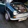
Hi all, I am currently attempting to do the micra swap, using a CG13 engine. Being an engineer I figured I'd work out my subframe design in CAD, saving any annoying trial and error. Obviously to do this I need some accurate models of a mini engine bay and a nissan engine. My plan was to use a technique called photogrammetry, which uses multiple images from various angles to reconstruct an accurate 3D model (if you've used google earth recently its how they make everything 3D). I figured that such models would be fairly useful to people so I would then upload them here for all to use. However, my mini isn't really an ideal candidate for this, as the lighting in my garage makes for poor photos, and the finish of my engine bay results in too many reflections (which confuse the software). It has also been repaired in the past and I'm not convinced the drivers side inner wing is quite right. So, I was wondering if anyone had a bare shell mini, preferably in primer they could take a bunch of pictures of the engine bay of? preferably with nice bright lighting (outdoors is ideal). Here is a handy tutorial on the process if anyone is interested: https://youtu.be/D6eqW6yk50k Once we have some photos I can run the programs and tidy up the mesh and all that and then put it up here for everyone. Now, if someone is willing to put in a fair bit of effort to get a really accurate model this tutorial: http://www.3dscansto...blog_post_id=19 shows a way of using spots of paint to give the software more features to identify (and thus a more accurate model) however it does involve a little bit of engine bay redecoration, I tried using strips of masking tape to give a little variation on mine and it did seem to help a bit.


Let me know if anyone wants to help with this!


Tom.


#2 Ethel

Ethel

    ..is NOT a girl!

  • TMF Team
  • PipPipPipPipPipPipPipPipPipPipPip
  • 25,946 posts
  • Local Club: none

Posted 17 September 2017 - 01:26 PM

Have you thought of contacting BMH or similar?


#3 tiger99

tiger99

    Crazy About Mini's

  • Members
  • PipPipPipPipPipPipPipPipPipPip
  • 8,584 posts
  • Location: Hemel Hempstead

Posted 17 September 2017 - 09:58 PM

Do you mean for a set of drawings? Good idea, if they are willing, but perhaps he would be better with the dimensions of an actual shell, incorporating all the deviations due to worn tooling? Or even better, both? Or several existing shells, so they can be averaged? Or did you mean scanning a new Heritage shell, with all their alleged recent problems? Any of these would be useful, some more so than others. It would be interesting to see the differences between shells!


Certainly this sort of information would be of immense usefulness to the Mini community in the future, when parts will have to be manufactured after Heritage have gone, or if and when IVA gets tightened up and mods need to be supported by proper engineering drawings and analysis, as will surely come eventually. It would also be useful to like-minded Mini modifiers, who plan ahead, rather than designing as they go. Nothing wrong with the latter, empirical approach by the way, it can give very good results as some of the build threads demonstrate, but if you need to go to an engineering company to make some bits (as I would need to for bending steel tubing, for example), a full drawing set is a very big advantage.


I wish this project success..It is important.


#4 Ethel

Ethel

    ..is NOT a girl!

  • TMF Team
  • PipPipPipPipPipPipPipPipPipPipPip
  • 25,946 posts
  • Local Club: none

Posted 17 September 2017 - 10:16 PM

I was hoping they might be interested in taking, or letting him take, some photos in exchange for a copy of his CAD file (possibly even cash). Surely it'd be of interest if you're knocking out shells, hopefully to the spec of the original drawings.


#5 nicklouse

nicklouse

    Moved Into The Garage

  • Members
  • PipPipPipPipPipPipPipPipPipPipPip
  • 18,599 posts
  • Location: Not Yorkshire
  • Local Club: Anonyme Miniholiker

Posted 17 September 2017 - 10:20 PM

DSN and co have a whole lot of scanned data you could pay for.


#6 benm

benm

    Mini Mad

  • Noobies
  • PipPipPipPip
  • 111 posts
  • Location: S.Wales

Posted 19 September 2017 - 05:14 AM

There is a full mini some one has designed on solid works available online

#7 benm

benm

    Mini Mad

  • Noobies
  • PipPipPipPip
  • 111 posts
  • Location: S.Wales

Posted 19 September 2017 - 05:16 AM

http://www.theminifo...bfram-cad-file/

#8 tiger99

tiger99

    Crazy About Mini's

  • Members
  • PipPipPipPipPipPipPipPipPipPip
  • 8,584 posts
  • Location: Hemel Hempstead

Posted 22 September 2017 - 07:09 PM

Any thoughts about the CAD software? Solidworks is only suitable for professionals who use it daily, because of cost, and it is Windoze only, which for me is a nuisance, but just about tolerable. If I was using CAD files to plan a project, I doubt that I would get over the initial learning curve in the 1 week free trial that you can get, far less design a major bit of metalwork. Any thoughts about converting to a format usable in free or cheap software? FreeCAD, perhaps? There are others too, like BRL-CAD. Or something up to a couple of hundred quid or so, more than that would be wasteful for the one project that I will do. Ideally not a huge learning curve, but that might be asking the impossible.


1 user(s) are reading this topic

0 members, 1 guests, 0 anonymous users