Hi chaps is there away I can test my fan I.e over ride it just to check operation ?
I tried unplugging the cable fro the thermostat housing but nothing ?
Thank you appreciate it as always

Testing Cooling Fan
Started by
leepol83
, Oct 08 2020 05:40 PM
13 replies to this topic
#2

Wazzah
-

- Noobies
-

- 142 posts
Mini Mad
- Location: Frankston
Posted 08 October 2020 - 08:35 PM
You don't mention whether your SPI or MPI so I offer a couple of solutions below.
The simplest way is to leave your engine idling until it gets hot enough to kick in.
From memory 92C is the kick in temp.
It is a pet hate of mine to idle engines for long periods so this method is up to you.
SPI's are relatively easy to override.
Disconnect the 2 wires off the radiator switch and bridge the 2 wires together.
The fan will work with the ignition on once bridged.
You'll have to remove the grill to get access.
MPI's are a bit harder as they have ECU control over the cooling fan.
Pin 28 from the ECU pulls in the cooling fan relay via a LG/B wire.
That wire runs through the bulkhead multiplug so the relay must be under the dash.
You could separate the multiplug and earth the wire coming from the cabin to pull the relay in.
The ignition must be on for the fan to work.
The multiplug sits behind the air filter so you'll have to remove this to gain access
#3
Steve220
-

- TMF+ Member
-
- 5,076 posts
Crazy About Mini's
- Location: Shropshire
- Local Club: BMC
Posted 08 October 2020 - 09:18 PM
You don't mention whether your SPI or MPI so I offer a couple of solutions below.
The simplest way is to leave your engine idling until it gets hot enough to kick in.
From memory 92C is the kick in temp.
It is a pet hate of mine to idle engines for long periods so this method is up to you.
SPI's are relatively easy to override.
Disconnect the 2 wires off the radiator switch and bridge the 2 wires together.
The fan will work with the ignition on once bridged.
You'll have to remove the grill to get access.
MPI's are a bit harder as they have ECU control over the cooling fan.
Pin 28 from the ECU pulls in the cooling fan relay via a LG/B wire.
That wire runs through the bulkhead multiplug so the relay must be under the dash.
You could separate the multiplug and earth the wire coming from the cabin to pull the relay in.
The ignition must be on for the fan to work.
The multiplug sits behind the air filter so you'll have to remove this to gain access
The fan motor relay is next to the fuel inertia switch on the bulkhead.
#4
leepol83
-
- Members
-
- 1,744 posts
Camshaft & Stage Two Head
Posted 09 October 2020 - 06:27 AM
You don't mention whether your SPI or MPI so I offer a couple of solutions below.
The simplest way is to leave your engine idling until it gets hot enough to kick in.
From memory 92C is the kick in temp.
It is a pet hate of mine to idle engines for long periods so this method is up to you.
SPI's are relatively easy to override.
Disconnect the 2 wires off the radiator switch and bridge the 2 wires together.
The fan will work with the ignition on once bridged.
You'll have to remove the grill to get access.
MPI's are a bit harder as they have ECU control over the cooling fan.
Pin 28 from the ECU pulls in the cooling fan relay via a LG/B wire.
That wire runs through the bulkhead multiplug so the relay must be under the dash.
You could separate the multiplug and earth the wire coming from the cabin to pull the relay in.
The ignition must be on for the fan to work.
The multiplug sits behind the air filter so you'll have to remove this to gain access
Brilliant thank you for taking the time to write all of this most appreciated ?? And it’s a MPI so I’ll probably just let It idle I think thanks again
Lee
#5
leepol83
-
- Members
-
- 1,744 posts
Camshaft & Stage Two Head
Posted 09 October 2020 - 06:30 AM
Cheers Steve
The fan motor relay is next to the fuel inertia switch on the bulkhead.
You don't mention whether your SPI or MPI so I offer a couple of solutions below.
The simplest way is to leave your engine idling until it gets hot enough to kick in.
From memory 92C is the kick in temp.
It is a pet hate of mine to idle engines for long periods so this method is up to you.
SPI's are relatively easy to override.
Disconnect the 2 wires off the radiator switch and bridge the 2 wires together.
The fan will work with the ignition on once bridged.
You'll have to remove the grill to get access.
MPI's are a bit harder as they have ECU control over the cooling fan.
Pin 28 from the ECU pulls in the cooling fan relay via a LG/B wire.
That wire runs through the bulkhead multiplug so the relay must be under the dash.
You could separate the multiplug and earth the wire coming from the cabin to pull the relay in.
The ignition must be on for the fan to work.
The multiplug sits behind the air filter so you'll have to remove this to gain access
#6
leepol83
-
- Members
-
- 1,744 posts
Camshaft & Stage Two Head
Posted 16 October 2020 - 07:20 PM
Hi chaps still no cooling fan and it did overheat a little the other day whilst idling went into the red in the gauge!!! been reading some threads and am I right in thinking if I unplug the temp sender from the thermo housing it should cut the fan in, didn’t fancy messing with the Ecu wiring if I’m honest ?
Thanks ?
Thanks ?
#7
Steve220
-
- TMF+ Member
-
- 5,076 posts
Crazy About Mini's
- Location: Shropshire
- Local Club: BMC
Posted 17 October 2020 - 11:58 AM
Hi chaps still no cooling fan and it did overheat a little the other day whilst idling went into the red in the gauge!!! been reading some threads and am I right in thinking if I unplug the temp sender from the thermo housing it should cut the fan in, didn’t fancy messing with the Ecu wiring if I’m honest ?
Thanks ?
Yes chap. If it doesn't do it then, I'd be looking into wiring, relays etc.
#8
leepol83
-
- Members
-
- 1,744 posts
Camshaft & Stage Two Head
Posted 17 October 2020 - 03:31 PM
Yes chap. If it doesn't do it then, I'd be looking into wiring, relays etc.Hi chaps still no cooling fan and it did overheat a little the other day whilst idling went into the red in the gauge!!! been reading some threads and am I right in thinking if I unplug the temp sender from the thermo housing it should cut the fan in, didn’t fancy messing with the Ecu wiring if I’m honest ?
Thanks ?
Okedokey I’ll check that first the yellow relay by the fuel inertia on the bulkhead is this the only one ? Any other wiring to check ?
#9
leepol83
-
- Members
-
- 1,744 posts
Camshaft & Stage Two Head
Posted 17 October 2020 - 06:39 PM
Don’t suppose anyone’s got the part number for the fan relay located in the bulkhead of the mpi mini ? Is it a
SRB 542 will this work ? Can’t find it in original yellow anywhere ?
Thanks
SRB 542 will this work ? Can’t find it in original yellow anywhere ?
Thanks
#10
Johnmar
-

- Just Joined
-
- 176 posts
Mini Mad
- Location: Drenthe (NL)
Posted 18 October 2020 - 06:13 AM
The SRB542 should work. This is just a standard 4-pin relay with the pins labeled:
85. (Ground (-))
86. Power (via a switch a control current)
87. The device to be switched on (this device have a ground connection itself or further up the wiring and this 87. becomes more or less a ground)
30. Feed
You can also search for "YWB10012" that will present you with a few yellow (more) original examples..
If one not just want to slap in a new relay but first want to test please read on:
Normally (when no power is applied) the switch in the relay (between 30 and 87) is open.
If there a current is placed on pin 86, it will flow through the spool in the relay to pin 85 (ground).
As the spool becomes electrified, it closes the circuit between pin 30 and 87 and current will flow
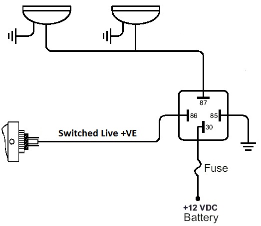
(drawing taken from www.xtremelandy.uk)
If you want to pin point and the problem you can remove the relays and measure with a multi meter:
1) check the resistance between 85 and a good ground connection (there may be some resistence).
2) if the ECU switches on the fan, there will be a positive feed on pin 86 (between 86 and 85 you should be able to measure 12v)
With this you've checked the wiring up to the relay
You can also check the wiring and connections from the relay (through the fan):
3) There should be a positive feed (12v) on pin 30 (measure against a good ground or pin 85)
4) You can and bridge pins 30 and 87 with a piece of wire and two spade connectors to test the wiring and fan after the relay (as you bypas the relay) as a test
Test 1+2: measure will tell you is everything is correct up to the relays.
Test 3+4: will tel you if all is ok after the relay (assuming that on pin 30 there is a 12v positive feed)
If all these tests are OK, then for sure it is the relay
Edited by Johnmar, 18 October 2020 - 06:57 AM.
#11
leepol83
-
- Members
-
- 1,744 posts
Camshaft & Stage Two Head
Posted 18 October 2020 - 07:22 AM
The SRB542 should work. This is just a standard 4-pin relay with the pins labeled:
85. (Ground (-))
86. Power (via a switch a control current)
87. The device to be switched on (this device have a ground connection itself or further up the wiring and this 87. becomes more or less a ground)
30. Feed
You can also search for "YWB10012" that will present you with a few yellow (more) original examples..
If one not just want to slap in a new relay but first want to test please read on:
Normally (when no power is applied) the switch in the relay (between 30 and 87) is open.
If there a current is placed on pin 86, it will flow through the spool in the relay to pin 85 (ground).
As the spool becomes electrified, it closes the circuit between pin 30 and 87 and current will flow
(drawing taken from www.xtremelandy.uk)
If you want to pin point and the problem you can remove the relays and measure with a multi meter:
1) check the resistance between 85 and a good ground connection (there may be some resistence).
2) if the ECU switches on the fan, there will be a positive feed on pin 86 (between 86 and 85 you should be able to measure 12v)
With this you've checked the wiring up to the relay
You can also check the wiring and connections from the relay (through the fan):
3) There should be a positive feed (12v) on pin 30 (measure against a good ground or pin 85)
4) You can and bridge pins 30 and 87 with a piece of wire and two spade connectors to test the wiring and fan after the relay (as you bypas the relay) as a test
Test 1+2: measure will tell you is everything is correct up to the relays.
Test 3+4: will tel you if all is ok after the relay (assuming that on pin 30 there is a 12v positive feed)
If all these tests are OK, then for sure it is the relay
Fantastic information thank you so much for taking the time, I’m not great with Electricial but my electrician mate will know what it all means, if I bridge 30 and 87 will this bring on the fan ?
Thanks again for taking the time to help me ??
Lee
#12
Johnmar
-
- Just Joined
-
- 176 posts
Mini Mad
- Location: Drenthe (NL)
Posted 18 October 2020 - 08:13 AM
Provided that your fault is the relay, bridging 30 and 87 will run the fan.
If there is a problem with the feed to pin 30, or the wiring from 87 via the fan to ground, it will not run.
(I'm not sure if you need the ignition to be on contact before pin 30 gets power and as me SPI is undergoing a full restoration and is only a bare shell at this moment without wiring, I can't test this for you.)
Hope this helps.
Edited by Johnmar, 18 October 2020 - 08:18 AM.
#13
leepol83
-
- Members
-
- 1,744 posts
Camshaft & Stage Two Head
Posted 18 October 2020 - 08:35 AM
Brilliant thank you honestly it’s most appreciated ????Provided that your fault is the relay, bridging 30 and 87 will run the fan.
If there is a problem with the feed to pin 30, or the wiring from 87 via the fan to ground, it will not run.
(I'm not sure if you need the ignition to be on contact before pin 30 gets power and as me SPI is undergoing a full restoration and is only a bare shell at this moment without wiring, I can't test this for you.)
Hope this helps.
#14
leepol83
-
- Members
-
- 1,744 posts
Camshaft & Stage Two Head
Posted 25 October 2020 - 06:15 PM
Sorted was the yellow relay on the bulkhead
Cheers all
Cheers all


1 user(s) are reading this topic
0 members, 1 guests, 0 anonymous users


