Jump to content


Photo
- - - - -

Adding Fuses For Accessories And Where To Get Power From


Best Answer humph , 29 April 2021 - 04:40 PM

good effort; not too far off 


the connections to terminals 87 and 30 are the wrong way round;  terminal 30 is by convention power in, and terminal 87 is power out


personally, i would install an additional (brown) wire from the starter solenoid to the relay (T30).  the reason being that if you take the feed to the relay from position1 on the fuse box then the additional load of the new circuits will have to be handled by the existing (brown) wire from the starter solenoid, which may or may not be able to handle the extra current load


the green wire you have marked from fuse position 4 to relay T86 is the trigger for the relay - when it's got 12volts on it, the relay will energise and connect T30 (power in) to T87 (power out).  it doesn't supply power to the downstream circuits hanging off the relay


if it was me, i'd take the green wire to the relay T86 from fuse position 3.  The downside of using position 4 is that if the fuse blows, you will lose all the circuits that are fed through the relay


hope this helps


Thanks KTS, your help is greatly appreciated. And thanks for spotting that my terminals were the wrong way around, think my relay diagram got rotated part way through me drawing the wiring up, sorted now.  So my corrected drawing looks like this;


51157130075_f50e3e46ae_b.jpg


I've removed the incorrect diagram from my original post so that nobody else uses it by mistake.

Go to the full post


  • Please log in to reply
21 replies to this topic

#1 humph

humph

    How bad can it Be?

  • TMF+ Member
  • PipPipPipPipPipPipPip
  • 1,065 posts

Posted 18 April 2021 - 07:46 PM

During my 69 Elf rebuild I am adding some accessories that the car didn’t leave the factory with, and want to have them fused. Please excuse the following dumb questions but I can’t claim to have any electrical knowledge.

The car originally had a 2 fuse box, I was thinking about upgrading this to a four fuse box

Was this;

https://www.minispar...|Back to search

Was think of using this;

https://www.minispar...|Back to search

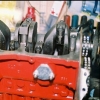
This is the wiring diagram for my car, currently showing a 2 fuse box. The car has a brand new loom which converts the car to negative earth and an alternator.

As can be seen always live is terminal 1, switched live is terminal 4. I want to add some of the new accessories to the two spare fuses, these are items like screen washer pump, radio, maybe a heated rear screen.

My main question is how do I get switched power to these spare fuses?

50958649248_77242e1148_3k.jpg


Edited by humph, 19 April 2021 - 10:19 AM.


#2 KTS

KTS

    Up Into Fourth

  • TMF+ Member
  • PipPipPipPipPipPipPipPipPip
  • 2,257 posts
  • Location: Herts

Posted 18 April 2021 - 08:21 PM

One way would be run another permanent live feed from the starter solenoid to a relay somewhere close to the fuse box. Use a connection from the existing terminal 2 / switched live fuse to trigger the relay. Output from the relay goes to the spare fuses giving you two additional switched live fuse positions

#3 phillrulz

phillrulz

    Super Mini Mad

  • Members
  • PipPipPipPipPipPip
  • 617 posts
  • Location: North West London

Posted 18 April 2021 - 09:26 PM

On my mini i did like KTS said,


Perm live from starter solenoid goes to a relay contact, the NO contact goes to my addition fuseboard. 


Coil of the relay is switched via a piggyback spade connector on the OEM fuseboard.


That way you dont burn your ignition switch or loom, you can also remove it all without leaving a trace or modifying the loom. 


#4 humph

humph

    How bad can it Be?

  • TMF+ Member
  • PipPipPipPipPipPipPip
  • 1,065 posts

Posted 19 April 2021 - 07:18 AM

Thanks guys, that seems like a pretty neat solution.  I'm assuming you guys kept the 2 fuse box and added another?  I'm beginning to wonder if that's what I should have done, but the 4 fuse box is mounted having drilled the inner wing.


What size/type of relay did you use?  Have you taken two supplies of the one pin, or used a 5 pin relay with two power pins?


https://www.autospar...ounting-bracket


KTS you mention switched power at terminal 2, but switched power on my diagram is terminal 4, was this a typo or am I misunderstanding?


Does the new switched supply need to come off that side of the box? or can it come off before the fuses?  I already have 4 green wires coming off the green switched terminal (the diagram above shows 3, but there is 4). I haven't established what the rogue one is yet but it looks like it may be the optional radio wiring that autosparks put in, not shown on the diagram)


https://www.autospar...k/media/AUD.pdf


Edited by humph, 19 April 2021 - 07:45 AM.


#5 KTS

KTS

    Up Into Fourth

  • TMF+ Member
  • PipPipPipPipPipPipPipPipPip
  • 2,257 posts
  • Location: Herts

Posted 19 April 2021 - 09:50 AM

i haven't switched from a 2 to a 4 fuse setup (..i've converted from 4 to 27 in my build)


a 30amp 4 pin (make/break) relay is all you should need.  5 pin (changeover) will do the same job, just that the 5th pin wouldn't be used


i took terminal 2 as the switched live as described in your original post 


from the diagram:

  • terminal 1 is permanent live power in (from starter solenoid)
  • terminal 2 is permanent live circuits fused supply.
  • terminal 3 is switched live power in (from the ignition switch)
  • terminal 4 is switched live circuits fused supply

for the replacement fusebox it's worth sticking with the same convention with power in using the left bank of connections, and fused circuit supplies (power out) using the right hand connectors 


#6 humph

humph

    How bad can it Be?

  • TMF+ Member
  • PipPipPipPipPipPipPip
  • 1,065 posts

Posted 19 April 2021 - 10:14 AM

Thanks KTS. I'm assuming then that your 27 box takes one supply and powers a number of fuses from that. My 4 gang doesn't do this, each fuse will need it's own supply. So it seems to me that this 30A 'ordinary make break' relay that has two powered pins when energised would suit my  situation, one pin per fuse I want to power.


https://www.autospar...ounting-bracket


http://www.minispare...|Back to search


By the way I've correct the first post to read terminal 4 for switched live, my error, thanks.


Edited by humph, 19 April 2021 - 10:26 AM.


#7 andyapanel

andyapanel

    Super Mini Mad

  • Members
  • PipPipPipPipPipPip
  • 562 posts

Posted 19 April 2021 - 11:41 AM

Have you approached Autosparks to make a loom for you? They are not expensive. They made me a new loom for my pickup, including relays and a fusebox (with bladed fuses) in the cabin.


#8 KTS

KTS

    Up Into Fourth

  • TMF+ Member
  • PipPipPipPipPipPipPipPipPip
  • 2,257 posts
  • Location: Herts

Posted 19 April 2021 - 12:06 PM

a standard 4 pin relay has just one output pin.  there's quite a helpful relay guide on this site https://www.12voltpl...dge-centre.html


to power 2 positions on the fuse box you can either connect two wires from a single crimp terminal at the relay to two connectors on the fuse box (i.e. positions 5 & 7) or run a single connector from the relay to position 5 and then use short link from there to position 7.  this can be either as a separate link or daisy chained off the crimp terminal at position 5.  both are acceptable, daisy chaining just means one less connector position on the fuse box is used


#9 gazza82

gazza82

    Up Into Fourth

  • Members
  • PipPipPipPipPipPipPipPipPip
  • 2,916 posts
  • Location: Bucks
  • Local Club: TMF+

Posted 19 April 2021 - 07:08 PM

Have you approached Autosparks to make a loom for you? They are not expensive. They made me a new loom for my pickup, including relays and a fusebox (with bladed fuses) in the cabin.


12 week production cycle at the moment!

#10 humph

humph

    How bad can it Be?

  • TMF+ Member
  • PipPipPipPipPipPipPip
  • 1,065 posts

Posted 19 April 2021 - 09:17 PM

Have you approached Autosparks to make a loom for you? They are not expensive. They made me a new loom for my pickup, including relays and a fusebox (with bladed fuses) in the cabin.

12 week production cycle at the moment!
My new loom is from autosparks, it’s their standard Elf one with mods for alternator, radio, and power socket.

Will be going for the relay option, happy with that, just need to size up the cable from my permanent live to match the existing. Thanks to KTS and philrullz for their help and patience.

Edited by humph, 19 April 2021 - 09:19 PM.


#11 humph

humph

    How bad can it Be?

  • TMF+ Member
  • PipPipPipPipPipPipPip
  • 1,065 posts

Posted 29 April 2021 - 11:42 AM

phillrulz, on 18 Apr 2021 - 10:26 PM, said:

On my mini i did like KTS said,

Perm live from starter solenoid goes to a relay contact, the NO contact goes to my addition fuseboard.

Coil of the relay is switched via a piggyback spade connector on the OEM fuseboard.

That way you dont burn your ignition switch or loom, you can also remove it all without leaving a trace or modifying the loom.


KTS, on 19 Apr 2021 - 10:50 AM, said:

i haven't switched from a 2 to a 4 fuse setup (..i've converted from 4 to 27 in my build)

a 30amp 4 pin (make/break) relay is all you should need. 5 pin (changeover) will do the same job, just that the 5th pin wouldn't be used

i took terminal 2 as the switched live as described in your original post

from the diagram:

  • terminal 1 is permanent live power in (from starter solenoid)
  • terminal 2 is permanent live circuits fused supply.
  • terminal 3 is switched live power in (from the ignition switch)
  • terminal 4 is switched live circuits fused supply
for the replacement fusebox it's worth sticking with the same convention with power in using the left bank of connections, and fused circuit supplies (power out) using the right hand connectors

So I've been looking at this and have drawn up this wiring proposal based on my understanding of the replies above.

ORIGINAL WIRING DIAGRAM REMOVED SO IT DOESN'T GET USED BY MISTAKE

Can anyone advise if this is correct before I go about putting it in?

I'm taking the switched live to the additional fuses from terminal 4. This means that anything fused by the additional fuses is covered by 2 fuses. Should I be taking this feed off terminal 3 or 4 i.e. before or after the switched supply fuse?

The only question then is fuse sizes. The relay will be 30 or 40 Amp.

Edited by humph, 29 April 2021 - 04:35 PM.


#12 Cooperman

Cooperman

    Uncle Cooperman, Voted Mr TMF 2011

  • TMF+ Member
  • PipPipPipPipPipPipPipPipPipPipPip
  • 23,036 posts
  • Location: Cambs.
  • Local Club: MCR, HAMOC, Chelmsford M.C.

Posted 29 April 2021 - 12:04 PM

On my cars I usually fit a 12 volt power source with a direct feed from the battery.

I use an exhaust 'cotton reel' and bolt it through the RH inner wing. Then the main battery line I fit to the cotton-reel other end (after I clean all the paint off). I then have an insulated 12 volt supply point to which I fit the main cable to the starter solenoid.

All the additional services can then come off from that power source to the extra fuse boxes. That way it is easy to have additional power when needed and it provides a great place to put the charger lead from a battery charger. I found a small red plastic cover to go over the cotton-reel live terminal.


#13 KTS

KTS

    Up Into Fourth

  • TMF+ Member
  • PipPipPipPipPipPipPipPipPip
  • 2,257 posts
  • Location: Herts

Posted 29 April 2021 - 12:27 PM

good effort; not too far off 


the connections to terminals 87 and 30 are the wrong way round;  terminal 30 is by convention power in, and terminal 87 is power out


personally, i would install an additional (brown) wire from the starter solenoid to the relay (T30).  the reason being that if you take the feed to the relay from position1 on the fuse box then the additional load of the new circuits will have to be handled by the existing (brown) wire from the starter solenoid, which may or may not be able to handle the extra current load


the green wire you have marked from fuse position 4 to relay T86 is the trigger for the relay - when it's got 12volts on it, the relay will energise and connect T30 (power in) to T87 (power out).  it doesn't supply power to the downstream circuits hanging off the relay


if it was me, i'd take the green wire to the relay T86 from fuse position 3.  The downside of using position 4 is that if the fuse blows, you will lose all the circuits that are fed through the relay


hope this helps


#14 humph

humph

    How bad can it Be?

  • TMF+ Member
  • PipPipPipPipPipPipPip
  • 1,065 posts

Posted 29 April 2021 - 04:40 PM   Best Answer

good effort; not too far off 


the connections to terminals 87 and 30 are the wrong way round;  terminal 30 is by convention power in, and terminal 87 is power out


personally, i would install an additional (brown) wire from the starter solenoid to the relay (T30).  the reason being that if you take the feed to the relay from position1 on the fuse box then the additional load of the new circuits will have to be handled by the existing (brown) wire from the starter solenoid, which may or may not be able to handle the extra current load


the green wire you have marked from fuse position 4 to relay T86 is the trigger for the relay - when it's got 12volts on it, the relay will energise and connect T30 (power in) to T87 (power out).  it doesn't supply power to the downstream circuits hanging off the relay


if it was me, i'd take the green wire to the relay T86 from fuse position 3.  The downside of using position 4 is that if the fuse blows, you will lose all the circuits that are fed through the relay


hope this helps


Thanks KTS, your help is greatly appreciated. And thanks for spotting that my terminals were the wrong way around, think my relay diagram got rotated part way through me drawing the wiring up, sorted now.  So my corrected drawing looks like this;


51157130075_f50e3e46ae_b.jpg


I've removed the incorrect diagram from my original post so that nobody else uses it by mistake.


Edited by humph, 03 May 2021 - 08:33 PM.


#15 KTS

KTS

    Up Into Fourth

  • TMF+ Member
  • PipPipPipPipPipPipPipPipPip
  • 2,257 posts
  • Location: Herts

Posted 29 April 2021 - 06:37 PM

That looks good.

15amp fuses should be sufficient to handle the loads


0 user(s) are reading this topic

0 members, 0 guests, 0 anonymous users