Jump to content


Photo
- - - - -

Fuel And Temp Guage's Are Not Working


  • Please log in to reply
10 replies to this topic

#1 nbw

nbw

    Learner Driver

  • Noobies
  • PipPip
  • 15 posts
  • Location: Essex

Posted 29 November 2021 - 01:46 PM

1996 Mini Tahiti


Hi all

I have an issue with both the Temp and Fuel gauge's not working


I have cleaned both the connectors on the fuel tank and the temp sensor.  But i am still not getting any feed back in the gauges.


For both not to work makes me wonder if there is something i am missing.


Anyone able to point me in the direction to look at?


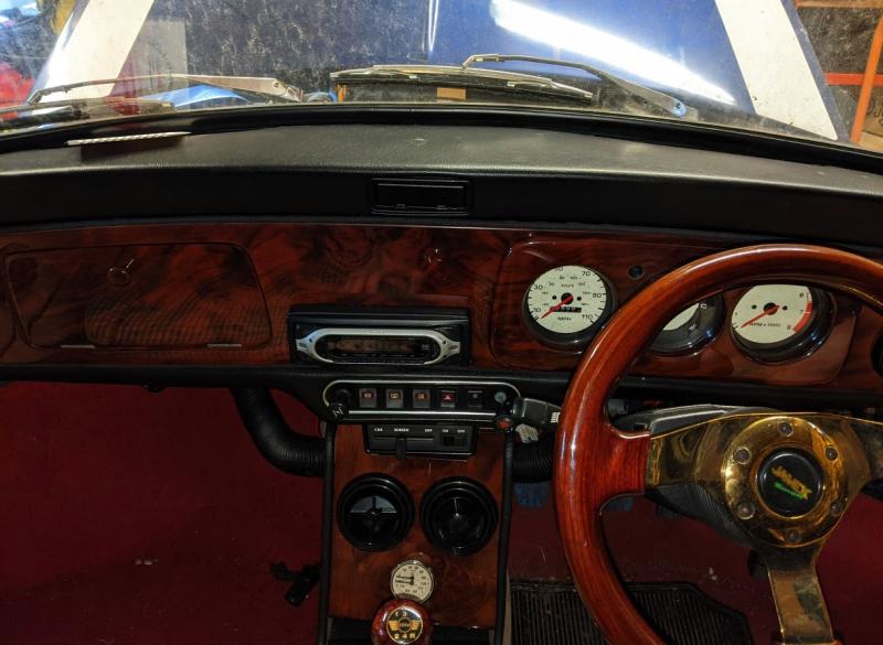
Photo of the dash below.


Can i ground the black and green cable going to the fuel sender to see if it goes to full?

The car has sat for a long time, with no fuel in.  Not sure if that helps identify where the issue is


3D0B202D-FD66-43F0-B129-5DF78AA14191.jpeg


#2 Spider

Spider

    Moved Into The Garage

  • Admin
  • PipPipPipPipPipPipPipPipPipPipPip
  • 13,904 posts
  • Location: NSW
  • Local Club: South Australian Moke Club

Posted 29 November 2021 - 06:52 PM

I'd say the Voltage Stabaliser is karput.


#3 nbw

nbw

    Learner Driver

  • Noobies
  • PipPip
  • 15 posts
  • Location: Essex

Posted 29 November 2021 - 08:42 PM

Hi
Thanks for the reply.

I have opened the dash up and tried to find the voltage stabilizer but I cannot. I am assuming it's built into the dash cluster dials and not easily accessible?

Thanks
Nick

Attached Files


#4 mini-mad-mark

mini-mad-mark

    One Carb Or Two?

  • Members
  • PipPipPipPipPipPipPip
  • 703 posts
  • Local Club: northants wot no brakes

Posted 29 November 2021 - 10:33 PM

Hopefully I recall this correctly - pretty sure it was on here - the older smiths gauges had a separate VR  plugged into the circuit board but the later ones (NipponSeiki - ?) have VR built into the dial I believe - not sure what the fix is for the later ones though sorry


I bet someone else will respond with a bit more help...


#5 Spider

Spider

    Moved Into The Garage

  • Admin
  • PipPipPipPipPipPipPipPipPipPipPip
  • 13,904 posts
  • Location: NSW
  • Local Club: South Australian Moke Club

Posted 29 November 2021 - 11:54 PM

Hopefully I recall this correctly - pretty sure it was on here - the older smiths gauges had a separate VR  plugged into the circuit board but the later ones (NipponSeiki - ?) have VR built into the dial I believe - not sure what the fix is for the later ones though sorry


I bet someone else will respond with a bit more help...


Thanks for bailing me out !

I know they have a Regulator, but I am not sure where they are, it makes sense though that it would be inside the assembly somewhere !

There's a fix here;-


https://www.theminif...tage-regulator/


#6 nbw

nbw

    Learner Driver

  • Noobies
  • PipPip
  • 15 posts
  • Location: Essex

Posted 30 November 2021 - 08:04 PM

Thanks both.  Looks like the fix i needed!  Parts ordered!


#7 cal844

cal844

    Crazy About Mini's

  • Members
  • PipPipPipPipPipPipPipPipPipPip
  • 9,486 posts
  • Location: Ballingry, Fife
  • Local Club: TFMOC

Posted 30 November 2021 - 10:18 PM

That's the correct fix that Spider linked, some of the part numbers may now be superceded but a decent parts Advisor should still cross reference

#8 nbw

nbw

    Learner Driver

  • Noobies
  • PipPip
  • 15 posts
  • Location: Essex

Posted 07 December 2021 - 09:21 PM

I am having a stinker with the guide chaps


I have been able to remove the temp voltage unit from the cluster

but i am unable to undo the brass nut to break the contact as part of the guide linked in the post above.  Correct me if i am wrong, but i am to break the current at the bolt


Attached File  PXL_20211207_204303576.jpg   29.69K   0 downloads

Attached File  PXL_20211207_204331723.jpg   28.21K   0 downloads
Attached File  PXL_20211207_204308958.jpg   29.56K   0 downloads


The image in the guide:

Attached File  f4d8feddb072a690a35cbe802f656f4f3e0a7fae.jpg   34.8K   0 downloads

Its becoming a tad frustrating as i cannot apply too much pressure as i feel i will damage the unit.


Any suggestions?


Thanks

Nick


Edited by nbw, 07 December 2021 - 09:24 PM.


#9 Tornado99

Tornado99

    One Carb Or Two?

  • Members
  • PipPipPipPipPipPipPip
  • 749 posts
  • Location: Vancouver

Posted 08 December 2021 - 12:13 AM

From the guide it seems to states to block the contact at thr brass nut/bolt and he used electrical tape (black blob wrapped around the brass in one image). So nothing about undoing the nut, just "breaking" the electrical contact. I'd use something better than e tape, as that tends to age poorly. A bit of heat shrink would be better i'd think.

#10 sonscar

sonscar

    Up Into Fourth

  • Members
  • PipPipPipPipPipPipPipPipPip
  • 2,721 posts
  • Location: crowle
  • Local Club: none

Posted 08 December 2021 - 08:24 AM

The nut will be welded to the brass arm so that the screw can be used to adjust it.Try removing the screw and sleeving the contact?Steve..

#11 Spider

Spider

    Moved Into The Garage

  • Admin
  • PipPipPipPipPipPipPipPipPipPipPip
  • 13,904 posts
  • Location: NSW
  • Local Club: South Australian Moke Club

Posted 08 December 2021 - 09:45 AM

That's a vibrating contact.

Just gently push them apart a little and slip some tape between them, than let them go to hold the tape captive.


1 user(s) are reading this topic

0 members, 1 guests, 0 anonymous users