I wrote up my attempts to improve the bump-steer of my 1978 Van (owned now for 40 years) about three years ago, but the post ended up with over 60 exchanges and I had always intended to cut to the chase and publish an edited version.
https://www.theminif...hl=+bump +steer
This might interest anyone who thinks that there's nothing particularly clever about having "lively" steering.
I had fitted 8.4" Discs with the requisite hubs (these 2-pots were later replaced with Metro Turbo 4-pots and ventilated discs).
However the tracking was wildly variable according to the height of the front suspension, which made the steering dangerously lively
With 6' lengths of 30x30 angle iron bolted to the discs (a very good way of exaggerating toe-in / out for what you might call an "initial approach" to bump-steer, 6' lengths giving about an 8x magnification of what is happening at the tyre diameter) I was seeing deviations of over 350mm (that's a foot to you !) which equates to about a 45mm change in toe measured at the tyres between full-droop and full-bump.
On the road this led to a floating sensation requiring constant steering inputs to keep the car in a straight line.
In case the disc-type hubs were the reason for my alarming bump steer, I checked two pairs of steering arms, one from disc-hubs, one from drum-hubs, and got the same results.
The cure obviously lay in moving the centre of the steering-rack-to-steering-arm ball-joints to a different vertical location.
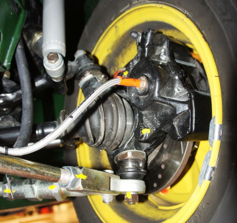
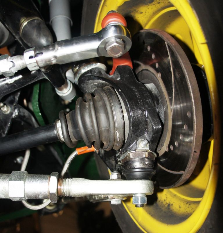
As you can't easily change the cone's location, nor then fine-tune it with spacers/shims, I resolved to use proper rose-joints (from McGills) as seen above.
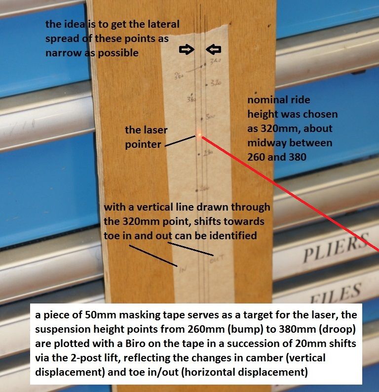
I first set about tweaking the steering arms' shapes, and swapped the standard ball-joints for the rose-joints so I could get the alignment I wanted, and was then able to shim - patiently - their position, until I ended up with virtually ZERO (2' of arc ?) bump-steer deviation over a whole120mm of suspension movement from full-droop to full-bump.
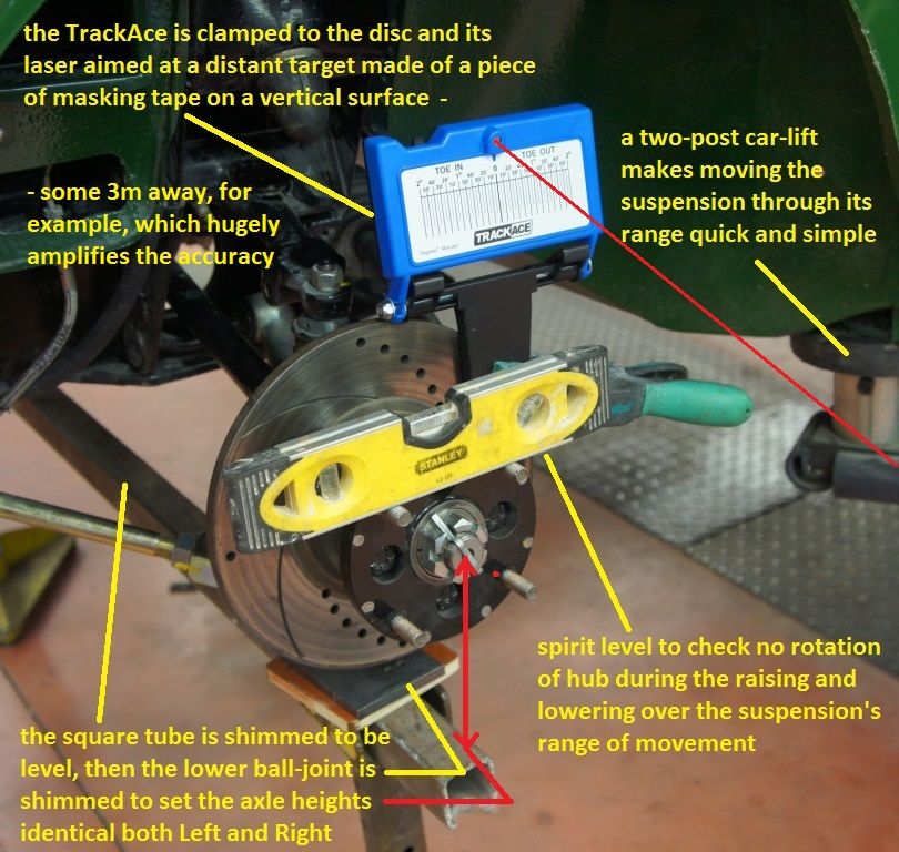
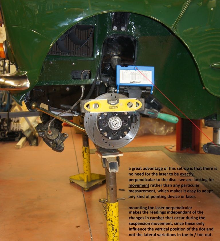
This can be checked with a cheap laser clamped perpendicularly to the disc, and in my case then projected 3m away onto a bit of masking tape.
These changes totally transformed the car.
For What It Is Worth, here are some shots of the modifications ; acknowledgements to K.Calver for pointing me in the right direction.
These mods are not for the faint-hearted, nor for beginners, but what follows worked very successfully for me (this being now written 3 + years on) and I would have found this info most helpful when I was casting around for a solution.
Rose-Joints - freed from the original conical fixing - make it possible to change the relative height of the track-rod end, and this is the only really practical "variable" that you can do on a Mini to address the bump-steer issue.
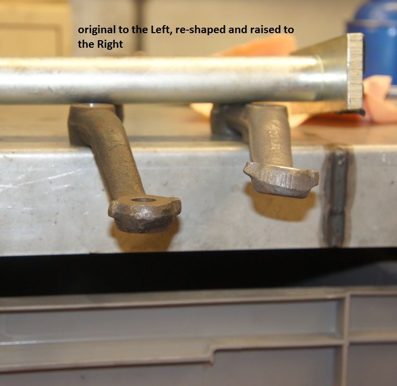
By shimming underneath the steering-arm-to-hub-interface - initially - to get a rough idea of where you need to go height-wise, the steering arms can be re-shaped so that they are a tad too high, and the rose-joint-to steering-arm-interface can then be shimmed for final adjustments.
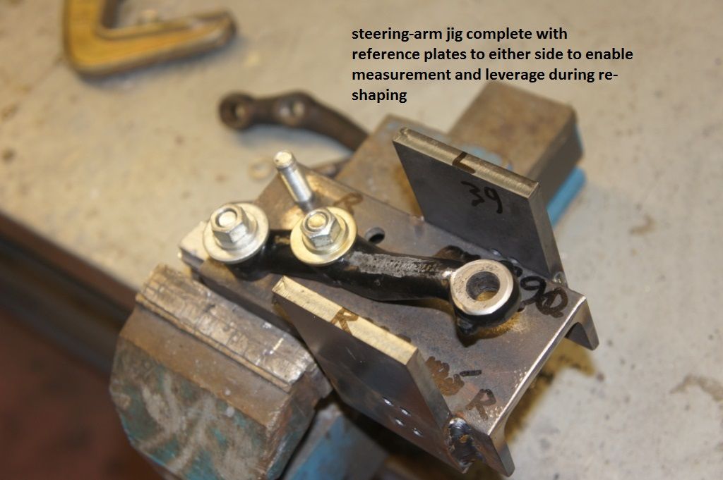
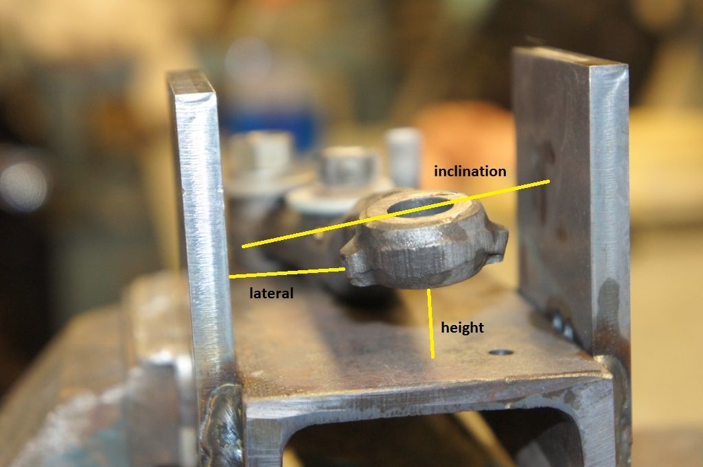
It's a good idea to make a jig from 8mm plate for what follows, so that you have some reference points to refer to when in the heat of the (very hot) action, there being three variables to consider.
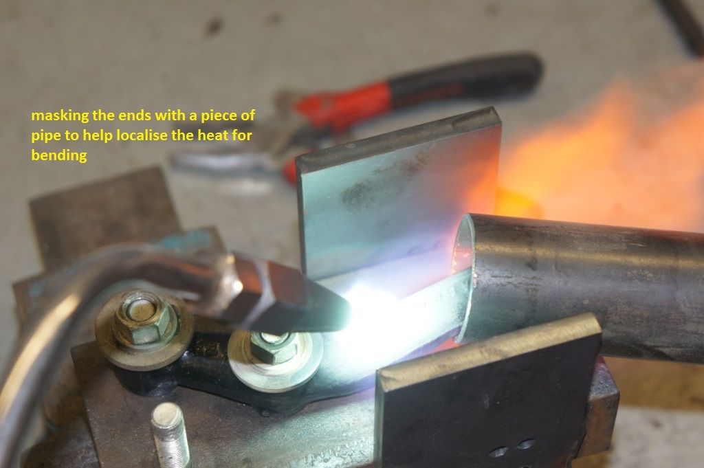
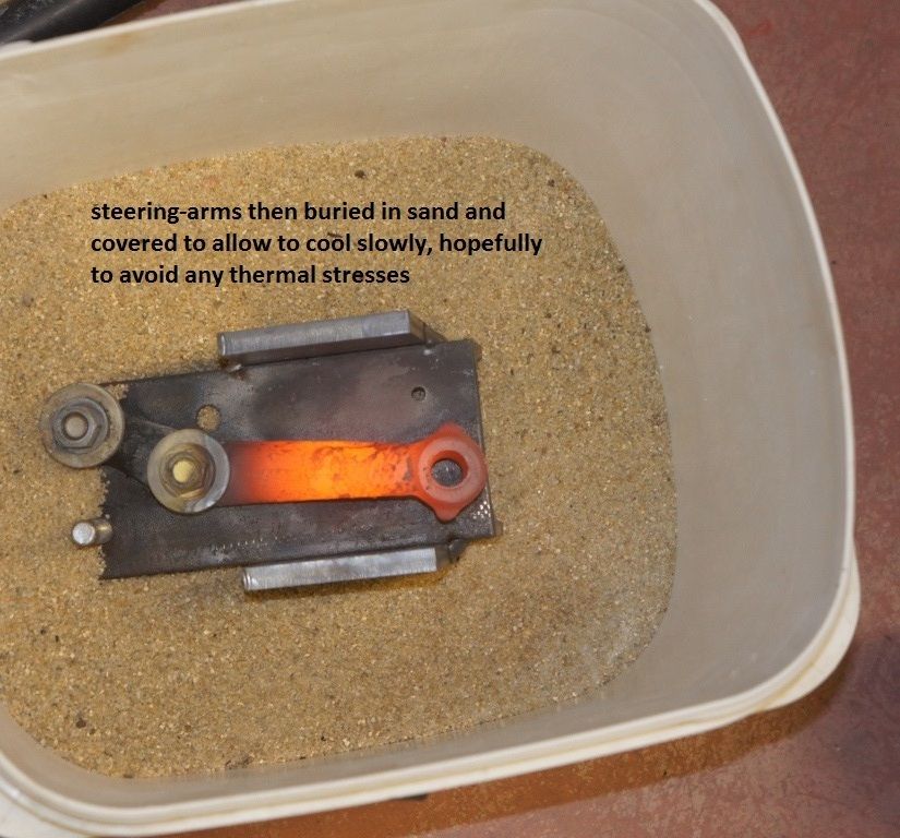
Using the versatile "blue-and-white-tipped multiadjustment tool", the forged steering arms can quite easily be coaxed to set their ends in a higher position, and at a suitable angle to make their alignment with the rose-joints spot on.
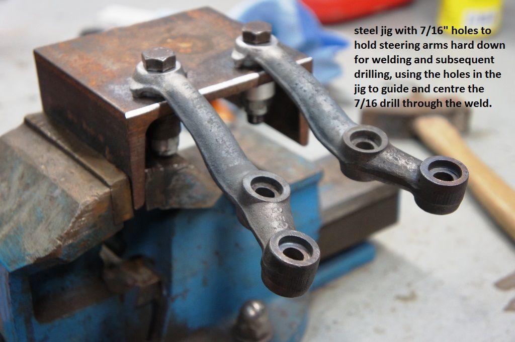
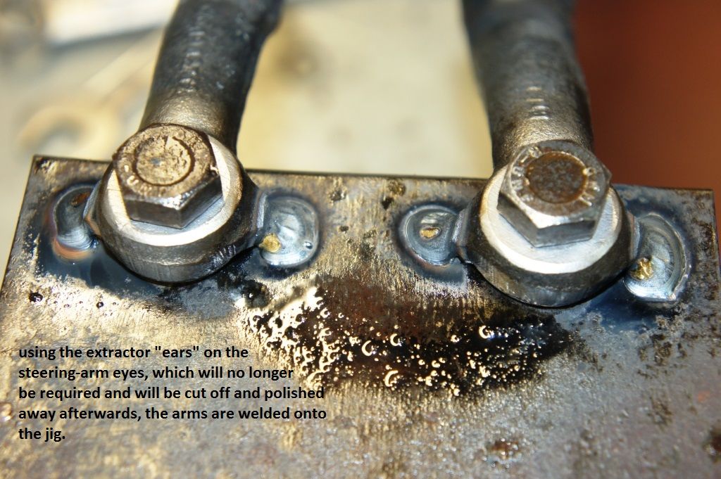
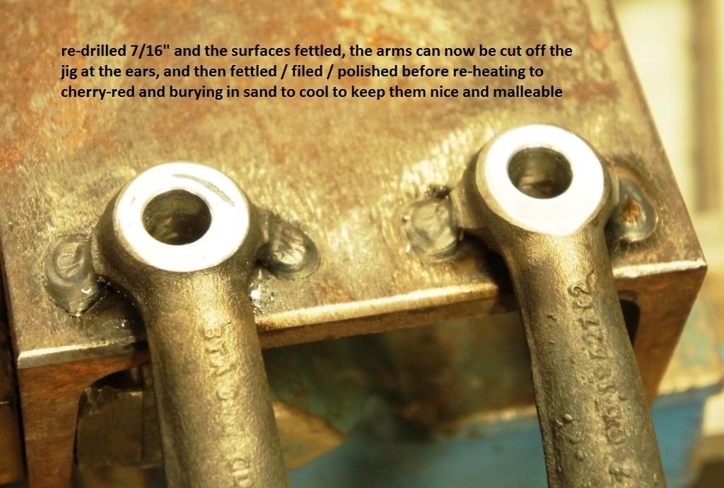
Once the shape is judged correct, the ears on the steering arms make for convenient places to weld them temporarily to a thick steel plate, 8mm or more (as it's going to guide a subsequent drilling), pre-drilled to 7/16".
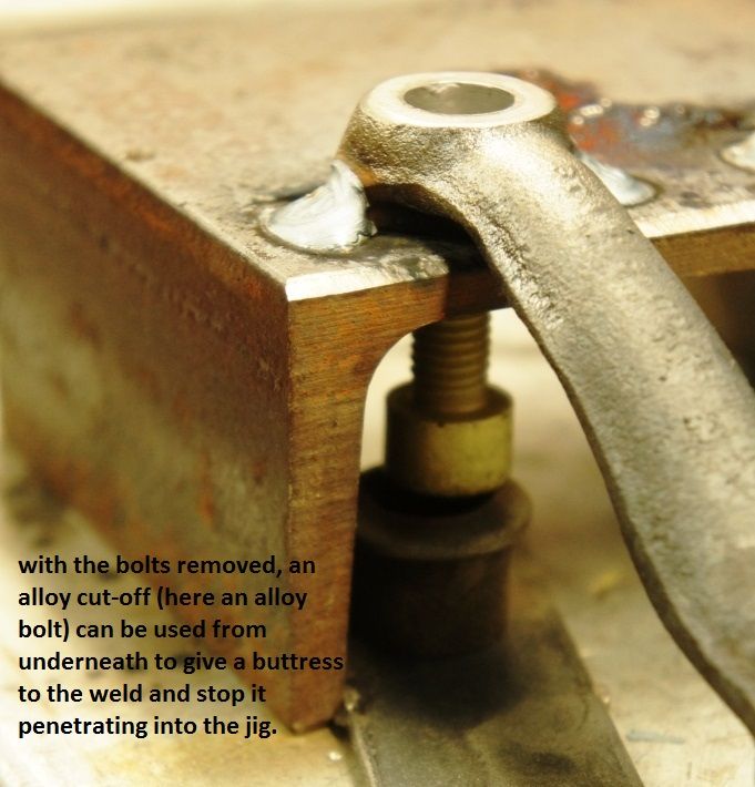
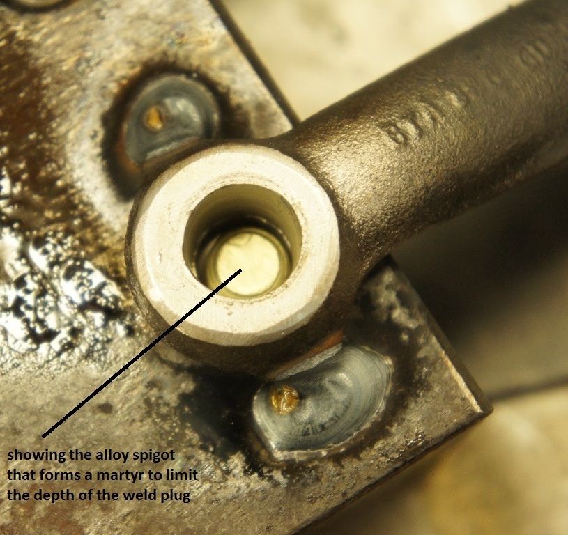
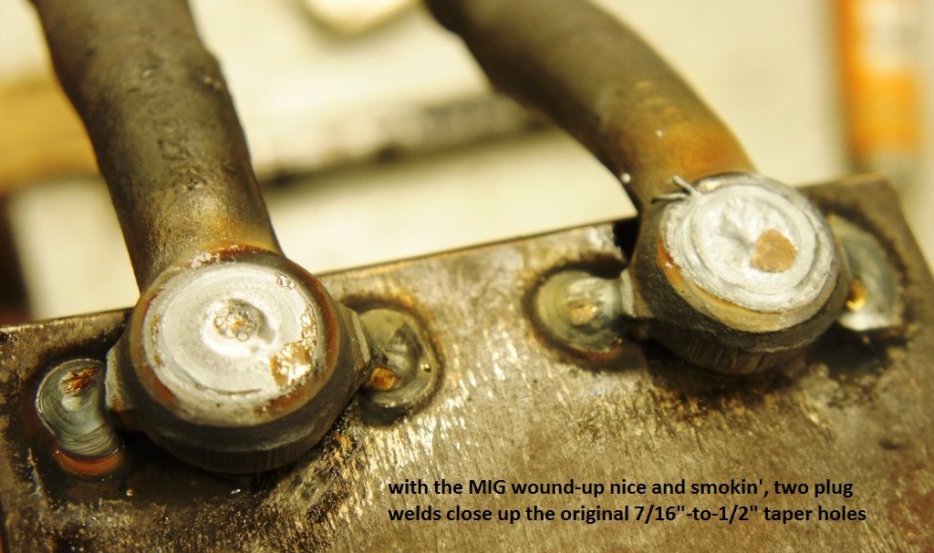
Next, the conical holes have to completely filled with weld, best done using a MIG, with some kind of non-ferrous bung or martyr protecting the steel plate underneath, so you don't weld the whole lot together.
Arms seen here blocked up solid.
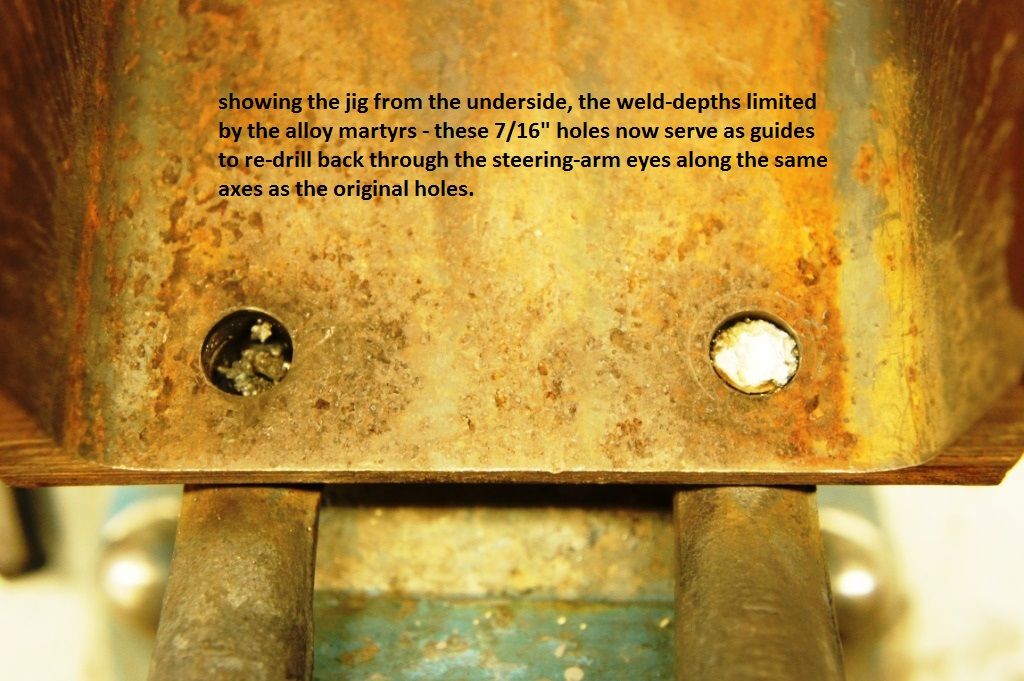
Now, by inverting the steel supporting structure, the arms can be drilled back from underneath to a 7/16" bore.
This method is, in my opinion, infinitely preferable to just drilling the arms out to 1/2", as is often seen, as the ball-joints end up being huge and ugly.
Regarding the rack, I replaced the original Van one with FAM7307HR (LHD, France, geddit ?) from Somerford, a brand-new unit, which is listed as MkII onwards ; I didn't compare the exact position of the inner track-rod pivots and threw the original Van one out, which was LHD too, but it seems highly unlikely that the rack geometry would be different - there aren't exactly many variants of this component ?
As a precaution, I TIG welded - big chamfers, very deep engagement of the cordon - threaded extending sleeves onto the McGill rose-joints, from memory about 1/2 long, so as to get even more of the steering-rack threads into the rose-joints ; this was probably not necessary, once the final adjustment was settled upon, but seemed a wise precaution when making all this.
(More to follow)
Edited by MontpellierVanMan, 29 July 2025 - 04:43 PM.


