So for clarity, where is Park/Brown-LGreen connected (stalk?) and is this a 12v feed or just an earth connection.


1989 Wipers Not Working
Started by
germini30
, Aug 28 2025 09:09 PM
22 replies to this topic
#16

gazza82
-
- TMF+ Member
-

- 3,086 posts
Up Into Fourth
- Location: Bucks
- Local Club: TMF+
Posted 03 September 2025 - 08:57 AM
#17
gazza82
-
- TMF+ Member
-
- 3,086 posts
Up Into Fourth
- Location: Bucks
- Local Club: TMF+
Posted 03 September 2025 - 09:01 AM
Sorry double-post due to that bl***y cloudflare
Edited by gazza82, 03 September 2025 - 09:03 AM.
#18
germini30
-
- Members
-
- 722 posts
One Carb Or Two?
Posted 04 September 2025 - 07:39 PM
All pins have feed except for pin 2 which is for park.
#19
gazza82
-
- TMF+ Member
-
- 3,086 posts
Up Into Fourth
- Location: Bucks
- Local Club: TMF+
Posted 14 September 2025 - 08:53 AM
All pins have feed except for pin 2 which is for park.
Realise that but where does pin 2 go? I know it goes back to the switch but where then?
Background:
I'm building a resto-mod based on an Austin A35 and using a 2-speed Mini/LandRover wiper motor. That operates off a 2-position rocker switch (Durite).
Pins 1,3,4 & 5 on the motor are simple but the park connection has me a little stumped even following the switch connection diagram.
When the switch is off (park) the switch connections go to pins 2 (park) and 5 (slow) on the motor.
For clarity when switch is in off position it bridges pins 1 (NLG) and 2A (RLG), position 1 bridges pins 2A (RLG) and 2B (12v switched live/LG) and position 2 bridges pins 2B (LG) and 3 (ULG).
So the park/off position is effectively bridges the pins 2 (park/NLG) and 5 (slow/RLG) on the motor if connected as suggested by the switch manufacturer.
#20
gazza82
-
- TMF+ Member
-
- 3,086 posts
Up Into Fourth
- Location: Bucks
- Local Club: TMF+
Posted 14 September 2025 - 09:00 AM
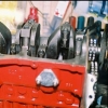
Actually think I've found the answer
 Screenshot_20250914_095624.jpg 31.84K
5 downloads
Screenshot_20250914_095624.jpg 31.84K
5 downloads
It does appear to bridge the slow and park connections on the motor.
Screenshot_20250914_095624.jpg 31.84K
5 downloadsIt does appear to bridge the slow and park connections on the motor.
Edited by gazza82, 14 September 2025 - 09:11 AM.
#21
Ethel
-

- TMF Team
-
- 26,580 posts
..is NOT a girl!
- Local Club: none
Posted 14 September 2025 - 10:37 AM
That is correct.
At the stalk the roller can bridge between 2 adjacent contacts:
Fast
+12v
Slow
Park
The top 2 should be obvious. When it's bridging slow to park, the motor runs on +12v that's attached to the park switch,until the park switch opens & cuts the supply to the stalk via the "park" wire.
#22
gazza82
-
- TMF+ Member
-
- 3,086 posts
Up Into Fourth
- Location: Bucks
- Local Club: TMF+
Posted 14 September 2025 - 10:42 AM
The top 2 were and easy to translate to my rocker switch. It was the parking circuit that threw me and that was my next diagram to check. That internal switch in the motor and how that is configured.
#23
Ethel
-
- TMF Team
-
- 26,580 posts
..is NOT a girl!
- Local Club: none
Posted 14 September 2025 - 11:58 AM
A rocker switch should be no different - 4 terminals with 3 intermediate positions. What switch are you using?


1 user(s) are reading this topic
0 members, 1 guests, 0 anonymous users


